EP1306247B1 - Einheit bestehend aus einem Seitenhohlelement, einem Fahrzeugrahmen und Vorrichtung und Fahrzeug die eine solche Einheit enthält - Google Patents
Einheit bestehend aus einem Seitenhohlelement, einem Fahrzeugrahmen und Vorrichtung und Fahrzeug die eine solche Einheit enthält Download PDFInfo
- Publication number
- EP1306247B1 EP1306247B1 EP02292656A EP02292656A EP1306247B1 EP 1306247 B1 EP1306247 B1 EP 1306247B1 EP 02292656 A EP02292656 A EP 02292656A EP 02292656 A EP02292656 A EP 02292656A EP 1306247 B1 EP1306247 B1 EP 1306247B1
- Authority
- EP
- European Patent Office
- Prior art keywords
- assembly
- vehicle
- duct
- air
- space
- Prior art date
- Legal status (The legal status is an assumption and is not a legal conclusion. Google has not performed a legal analysis and makes no representation as to the accuracy of the status listed.)
- Expired - Lifetime
Links
Images

Classifications
-
- B—PERFORMING OPERATIONS; TRANSPORTING
- B62—LAND VEHICLES FOR TRAVELLING OTHERWISE THAN ON RAILS
- B62D—MOTOR VEHICLES; TRAILERS
- B62D25/00—Superstructure or monocoque structure sub-units; Parts or details thereof not otherwise provided for
- B62D25/04—Door pillars ; windshield pillars
-
- B—PERFORMING OPERATIONS; TRANSPORTING
- B60—VEHICLES IN GENERAL
- B60H—ARRANGEMENTS OF HEATING, COOLING, VENTILATING OR OTHER AIR-TREATING DEVICES SPECIALLY ADAPTED FOR PASSENGER OR GOODS SPACES OF VEHICLES
- B60H1/00—Heating, cooling or ventilating devices
- B60H1/00507—Details, e.g. mounting arrangements, desaeration devices
- B60H1/00557—Details of ducts or cables
- B60H1/00564—Details of ducts or cables of air ducts
-
- B—PERFORMING OPERATIONS; TRANSPORTING
- B60—VEHICLES IN GENERAL
- B60H—ARRANGEMENTS OF HEATING, COOLING, VENTILATING OR OTHER AIR-TREATING DEVICES SPECIALLY ADAPTED FOR PASSENGER OR GOODS SPACES OF VEHICLES
- B60H1/00—Heating, cooling or ventilating devices
- B60H1/24—Ventilating devices where the heating or cooling is irrelevant
- B60H1/241—Ventilating devices where the heating or cooling is irrelevant characterised by the location of ventilation devices in the vehicle
- B60H1/243—Ventilating devices where the heating or cooling is irrelevant characterised by the location of ventilation devices in the vehicle located in the lateral area (e.g. doors, pillars)
Definitions
- the invention relates to an assembly for a vehicle, this assembly comprising a lateral duct of frame amount of the vehicle, the side duct allowing a circulation of air.
- the invention also relates to a heating, ventilation and air conditioning for a vehicle, this installation using at least one set as mentioned above.
- the invention furthermore relates to a vehicle of the type comprising an installation of heating, ventilation and air conditioning, the installation used also including at least a set as mentioned above.
- heating and air conditioning systems including ducts used to convey air processed to distribution outlets, these being distributed inside the cockpit of a vehicle.
- a vehicle with a frame with the particular characteristics mentioned previously can not incorporate a belt system in the same way as a vehicle comprising a conventional framework, because of the need to achieve air circulation to the interior of some elements of the frame.
- the purpose of the present invention is therefore to propose a set for a vehicle comprising a side duct of a frame stud of the vehicle and presenting means allowing the circulation of air, this assembly being also able to cooperate with a seat belt system.
- Another object of the invention is to propose a heating, ventilation and air conditioning using at least one set to the above technical problem, as well as a vehicle using an installation comprising at least one such together.
- the invention firstly the subject of a vehicle assembly, comprising a vehicle frame stud lateral duct, this lateral duct allowing a circulation of air.
- the side duct also includes a portion having two air passages separated by a space able to be crossed by a strap of a system of seatbelt.
- the invention thus proposes a set fulfilling the dual function of letting circulate the air at the lateral amount of framework, but also to allow a system of classic seatbelt to be able to cooperate with this side amount, providing a suitable space to allow the passage of the strap.
- the seat belt system and the side duct of the stud's upright vehicle constitute a compact group of elements, allowing to have excellent benefits aeraulic inside the cabin.
- the specific configuration adopted allows the whole according to the invention to be installed on vehicles designed for receive a classic framework, without having to modify the general shape of the vehicle.
- the lateral duct comprises a lower part and an upper part, each parts having a first end passing through of air and a second end comprising the two air passages.
- the second ends of lower and upper parts are able to cooperate with each other.
- the particularity quoted above is characteristic of a process of assembly of the assembly with the belt system of security that must remain simple.
- this two-part realization is especially interesting in the sense that it allows, in a first time, to pass the strap of the system of seat belt through the space provided for this effect, then, in a second step only, connect the two parts to each other at the level of second ends.
- the operation of the passage of the strap in the indicated space would be much more delicate to achieve without such a configuration having access to space before the mounting of two parts of the lateral amount one on the other.
- the set according to the invention comprises a lining of the frame of the vehicle on which is fixed a surface of the lower part of the side duct facing towards the outside of the vehicle, this lining supporting a winder of the seat belt system.
- this set also includes a shoulder harness the framework on which is fixed a surface of the upper part of the side duct facing towards inside the vehicle, this harness supporting a return of the seat belt system.
- the space capable of being traversed by the seat belt system strap is located about halfway up the vehicle. This allows advantageously to comply with vehicles already existing, which could be adapted to receive assemblies according to the invention.
- the sum of the sections of the two air passages is greater than or equal to the section average of the lower part of the lateral duct.
- the losses during the flow of air in the lateral ducts are therefore weak because of this specific provision.
- the space inside which the strap is shaped like water drop extending in a main direction of the lateral duct is shaped like water drop extending in a main direction of the lateral duct.
- Another object of the invention is a heating, ventilation and vehicle air conditioning, this installation comprising at least one assembly as cited previously.
- a last object of the invention is a vehicle of the type comprising an installation of heating, ventilation and air conditioning, this vehicle comprising at least one assembly as described above.
- a set 1 intended for use in a vehicle (no shown) comprising a heating installation, ventilation and air conditioning.
- the invention is intended to be implemented in a vehicle including 2 upright hollow side ducts of a frame of the vehicle, these lateral ducts 2 used for the circulation of air for the installation of heating, ventilation and air conditioning.
- the frame of a vehicle includes generally side jambs and a frame (not shown)
- Side amount means the part of the frame of the vehicle which is at a level side wall of the car, between two rows of Seat (s).
- this type of vehicle thus having a row of front seat (s) and a row of rear seat (s), the uprights There are two sides, each placed on one side of the vehicle. Note that for vehicles of the type four or five doors, side jambs separate on each side of the vehicle the front and rear doors.
- these hollow side pillars can also be used at the back of the car, close and set back from a row of rear seat (s).
- Each lateral amount of the frame includes structural elements and organs allowing the circulation of air.
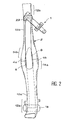
- the assembly 1 according to the invention therefore includes a lateral duct 2 allowing the air circulation, this lateral duct 2, preferably made of plastic material, being provided with a portion having two air passages 4a, 4b.
- the two air passages 4a, 4b are separated by a space 6 able to be crossed by a strap 8 a seat belt system.
- the lateral duct 2 comprises a lower part 10a and a part upper 10b.
- the lower part 10a of the duct lateral 2 comprises a first end 12a passing through single air and a second end 14a comprising the two air passages 4a, 4b.
- the upper part 10b of the lateral duct 2 which also comprises a first end 12b to single air passage, as well that a second end 14b comprising both passages 4a, 4b.
- the lower parts 10a and higher 10b of the lateral duct 2 are able to be connected tightly, preferably by simple nesting. This connection is made at the level of their respective second ends 14a, 14b, in connecting the two passages 4a, 4b defining the space 6 through which the webbing 8 of the seatbelt.
- the sum of the sections of the two passages 4a, 4b is greater than or equal to middle section of the lower part 10a of the duct lateral 2. It should be noted that the term section average of the bottom 10a, a section any of this lower part 10a not lying not near the second end 14a, the section in this area being almost constant as one can see it in figure 2.
- Space 6 delimited by seconds ends 14a, 14b of the portions 10a, 10b of the duct lateral 2, preferably takes the form of a drop of water extending in a principal direction from lateral duct 2.
- This main direction is the one of a longitudinal axis, generally oriented in the sense of vehicle height and extending generally from the floor to the roof of this vehicle.
- this space 6 can be located halfway up the vehicle, this being particularly suitable when the use of the seat belt system by a passenger or driver.
- the assembly 1 according to the invention is also provided with a plurality of structural elements intended partly to constitute in part the amount side of the assembly 1, and secondly to support the seat belt system.
- the set 1 includes a liner 16, this lining 16 being preferably fixed by welding to the frame of the vehicle, for example on the floor.
- the lining 16, preferably metallic, is oriented towards the inside of the vehicle with respect to the exterior body of the vehicle ( Figure 1).
- Sure the lining 16, is attached a winder 18 belonging to the seat belt system.
- the assembly 1 comprises a harness 20 fixed on an upper part of the side jamb of the frame of the vehicle.
- the shoulder 20, preferably metallic, is placed on a surface of the part upper amount that is facing inwards of the vehicle.
- On the shoulder 20 is fixed a reference 22 belonging to the seat belt system.
- the portion of the strap 8 lying under the space 6 slide side outside of the vehicle so that this strap 8 is driver or passenger, while the portion of the strap 8 lying above the space 6 slide on the inside of the vehicle so that this strap 8 is manipulable by a driver or a passenger inside the vehicle.
- the assembly 1 has a reinforcement outside structure 24, preferably fixed by welding on the one hand to the lining 16, and on the other hand to 20. It should be noted that the upper part of the 10b of the lateral duct 2, located between the reinforcement 24 and the shoulder 20 is also attached to the external reinforcement 24, for example using a rivet preferably made of plastic.
- Set 1 also includes a lower cladding 26a and an upper cladding 26b, each of these elements having a main function aesthetic, and preferably being plastic.
- the lower skin 26a is fixed on a surface of the lining 16, this surface being oriented towards the inside of the vehicle, so this trim is visible to a driver or passenger located inside the vehicle.
- the upper covering 26b is fixed on a surface of shoulder 20 facing the interior of the vehicle for the same reasons as those mentioned above.
- This assembly comprising both the lateral duct 2, the different structural elements reported, as well as seat belt system, is carried out from the following way.
- the winder 18 is installed on the lower part of the lining 16 of the amount lateral.
- the invention also relates to a heating, ventilation and air conditioning for a motor vehicle, this installation comprising at least one assembly 1 such that that described above, and preferably comprising two of these sets 1.
- the invention also relates to a vehicle comprising a heating installation, ventilation and air conditioning, this installation using at least one set 1 as described above, and preferably including two of these sets 1.
Landscapes
- Engineering & Computer Science (AREA)
- Mechanical Engineering (AREA)
- Physics & Mathematics (AREA)
- Thermal Sciences (AREA)
- Chemical & Material Sciences (AREA)
- Combustion & Propulsion (AREA)
- Transportation (AREA)
- Air-Conditioning For Vehicles (AREA)
- Automotive Seat Belt Assembly (AREA)
Claims (11)
- Gesamtheit (1) für ein Fahrzeug, welche eine seitliche Leitung (2) einer Tragwerkssäule des Fahrzeugs aufweist, wobei diese Leitung (2) eine Luftzirkulation erlaubt, dadurch gekennzeichnet, dass die Leitung (2) einen Abschnitt aufweist, der zwei Luftdurchgänge (4a, 4b) aufweist, die durch einen Raum (6) getrennt sind, der fähig ist, von einem Gurt (8) eines Sicherheitsgurtsystems durchquert zu werden.
- Gesamtheit (1) nach Anspruch 1, dadurch gekennzeichnet, dass die Leitung (2) einen unteren Teil (10a) und einen oberen Teil (10b) aufweist, wobei jeder der Teile (10a, 10b) ein erstes Ende (12a, 12b) mit einem einzigen Luftdurchgang und ein zweites Ende (14a, 14b) aufweist, welches die zwei Luftdurchgänge (4a, 4b) umfasst, wobei die zweiten Enden (14a, 14b) des unteren Teils (10a) und des oberen Teils (10b) geeignet sind, miteinander zusammenzuwirken.
- Gesamtheit (1) nach Anspruch 2, dadurch gekennzeichnet, dass diese Gesamtheit (1) eine Einlage (16) des Tragwerks umfasst, an welcher eine Oberfläche des unteren Teils (10a) der Leitung (2) befestigt ist, die nach außen vom Fahrzeug gerichtet ist, wobei diese Einlage (16) eine Spannrolle (18) des Sicherheitsgurtsystems trägt.
- Gesamtheit (1) nach Anspruch 2 oder 3, dadurch gekennzeichnet, dass diese Gesamtheit (1) ein Gehängeteil (20) (frz. baudrier) des Tragwerks umfasst, an welcher eine Oberfläche des oberen Teils (10b) der Leitung (2) befestigt ist, die nach innen vom Fahrzeug gerichtet ist, wobei dieses Gehängeteil (20) ein Umkehrmittel (22) des Sicherheitsgurtsystems trägt.
- Gesamtheit (1) nach einem der Ansprüche 2 bis 4, dadurch gekennzeichnet, dass diese Gesamtheit (1) eine untere Verkleidung (26a) umfasst, die an einer Oberfläche der Einlage (16) befestigt ist, die zum Inneren des Fahrzeugs hin gerichtet ist.
- Gesamtheit (1) nach Anspruch 4 oder Anspruch 5, dadurch gekennzeichnet, dass diese Gesamtheit (1) eine obere Verkleidung (26b) umfasst, die an einer Oberfläche des Gehängeteils (20) befestigt ist, die zum Inneren des Fahrzeugs hin gerichtet ist.
- Gesamtheit (1) nach irgendeinem der vorangegangenen Ansprüche, dadurch gekennzeichnet, dass der Raum (6), welcher geeignet ist, von dem Gurt (8) des Sicherheitsgurtsystems durchquert zu werden, sich in etwa auf mittlerer Höhe des Fahrzeuges befindet.
- Gesamtheit (1) nach irgendeinem der Ansprüche 2 bis 7, dadurch gekennzeichnet, dass die Summe der Querschnitte der zwei Luftdurchgänge (4a, 4b) größer oder gleich dem mittleren Querschnitt des unteren Teils (10a) der Leitung (2) ist.
- Gesamtheit (1) nach irgendeinem der vorangegangenen Ansprüche, dadurch gekennzeichnet, dass der Raum (6) von einer Art Wassertropfenform ist, die sich in einer Hauptrichtung der Leitung (2) erstreckt.
- Vorrichtung zur Beheizung, Belüftung und Klimatisierung für ein Fahrzeug, dadurch gekennzeichnet, dass sie mindestens eine Gesamtheit (1) nach einem der vorangegangenen Ansprüche aufweist.
- Fahrzeug von der Art, welches eine Vorrichtung zur Beheizung, Belüftung und Klimatisierung aufweist, dadurch gekennzeichnet, dass die Vorrichtung mindestens eine Gesamtheit (1) nach irgendeinem der Ansprüche 1 bis 9 aufweist.
Applications Claiming Priority (2)
| Application Number | Priority Date | Filing Date | Title |
|---|---|---|---|
| FR0113961A FR2831488B1 (fr) | 2001-10-29 | 2001-10-29 | Ensemble comprenant un montant lateral creux d'une ossature d'un vehicule et installation et vehicule utilisant un tel ensemble |
| FR0113961 | 2001-10-29 |
Publications (2)
| Publication Number | Publication Date |
|---|---|
| EP1306247A1 EP1306247A1 (de) | 2003-05-02 |
| EP1306247B1 true EP1306247B1 (de) | 2005-12-28 |
Family
ID=8868829
Family Applications (1)
| Application Number | Title | Priority Date | Filing Date |
|---|---|---|---|
| EP02292656A Expired - Lifetime EP1306247B1 (de) | 2001-10-29 | 2002-10-25 | Einheit bestehend aus einem Seitenhohlelement, einem Fahrzeugrahmen und Vorrichtung und Fahrzeug die eine solche Einheit enthält |
Country Status (3)
| Country | Link |
|---|---|
| EP (1) | EP1306247B1 (de) |
| DE (1) | DE60208298T2 (de) |
| FR (1) | FR2831488B1 (de) |
Families Citing this family (1)
| Publication number | Priority date | Publication date | Assignee | Title |
|---|---|---|---|---|
| DE102008024430B4 (de) * | 2008-05-20 | 2017-03-02 | Dr. Ing. H.C. F. Porsche Aktiengesellschaft | Kraftfahrzeug mit Luftkanalabschnitten für die Klimatisierung des Fahrzeuginnenraums |
Family Cites Families (5)
| Publication number | Priority date | Publication date | Assignee | Title |
|---|---|---|---|---|
| DE2610050A1 (de) * | 1976-03-11 | 1977-09-15 | Daimler Benz Ag | Vorrichtung zum beaufschlagen der hinter einer mittelsaeule angeordneten seitenscheiben, insbesondere eines personenkraftwagens |
| FR2659908B1 (fr) | 1990-03-23 | 1994-07-01 | Renault | Systeme de chauffage, de ventilation et de climatisation pour habitacles de vehicules automobiles. |
| FR2717745B1 (fr) | 1994-03-24 | 1996-05-15 | Valeo Thermique Habitacle | Installation de chauffage-climatisation de l'habitacle d'un véhicule. |
| SE512091C2 (sv) * | 1998-05-25 | 2000-01-24 | Volvo Ab | Motorfordon innefattande en lastbärande stolpe |
| JP3775140B2 (ja) * | 1999-11-08 | 2006-05-17 | スズキ株式会社 | 自動車の換気構造 |
-
2001
- 2001-10-29 FR FR0113961A patent/FR2831488B1/fr not_active Expired - Fee Related
-
2002
- 2002-10-25 EP EP02292656A patent/EP1306247B1/de not_active Expired - Lifetime
- 2002-10-25 DE DE60208298T patent/DE60208298T2/de not_active Expired - Lifetime
Also Published As
| Publication number | Publication date |
|---|---|
| FR2831488A1 (fr) | 2003-05-02 |
| FR2831488B1 (fr) | 2004-01-16 |
| EP1306247A1 (de) | 2003-05-02 |
| DE60208298D1 (de) | 2006-02-02 |
| DE60208298T2 (de) | 2006-07-13 |
Similar Documents
| Publication | Publication Date | Title |
|---|---|---|
| CA2235498C (fr) | Vehicule routier ultra-leger | |
| FR3002200A1 (fr) | Structure porteuse de vehicule automobile | |
| EP1432603B1 (de) | Stufenheck-kraftfahrzeug | |
| EP1306247B1 (de) | Einheit bestehend aus einem Seitenhohlelement, einem Fahrzeugrahmen und Vorrichtung und Fahrzeug die eine solche Einheit enthält | |
| EP1084942A1 (de) | Rückwärtige Bodenplatte formende Struktur und Verfahren zur Herstellung eines Kraftfahrzeugs mit einer solchen Struktur | |
| FR2922179A1 (fr) | Structure de caisse de vehicule automobile et vehicule comportant une telle structure de caisse. | |
| EP1860022B1 (de) | Unterbodenverkleidung eines Kraftfahrzeugs und eine solche Verkleidung umfassendes Kraftfahrzeug | |
| FR2924674A1 (fr) | Structure de caisse de vehicule automobile | |
| WO2024115162A1 (fr) | Renfort pour un support d'enrouleur de ceinture de sécurité de véhicule | |
| EP1100698B1 (de) | Airbaganordnung zum kraftfahrzeuginsassenschutz bei seitenaufprall | |
| FR2798339A1 (fr) | Dispositif d'aide au deploiement d'un coussin gonflable de vehicule automobile | |
| FR3020793A1 (fr) | Tablier avant pour vehicule automobile. | |
| EP3505425B1 (de) | Lokale behandlung auf einschichtboden der eingänge und verteilung der belastung bei seitlichem aufprall | |
| EP1588896B1 (de) | Hintere Abdeckung für ein Kraftfahrzeug | |
| FR3160376A1 (fr) | Longeron de véhicule automobile renforcé et ensemble de soubassement comportant un tel longeron | |
| FR2855097A1 (fr) | Nouvelle roue notamment en alliage leger pour vehicule automobile, et procede de fabrication d'une telle roue | |
| FR3072638B1 (fr) | Agencement d'une caisse de vehicule et procede de realisation associe | |
| FR2831487A1 (fr) | Ensemble pour vehicule comprenant un conduit et un dispositif d'habillage interieur, procede de montage de l'ensemble et dispositif d'habillage interieur | |
| EP3377391B1 (de) | Verbessertes profil für die struktur eines landfahrzeugs für den öffentlichen personenverkehr, struktur und fahrzeug mit solch einem profil | |
| FR2758783A1 (fr) | Ensemble de poste avant d'habitacle de vehicule automobile | |
| WO2013060959A1 (fr) | Caisse de vehicule automobile et son brancard arriere avec toit trans | |
| FR3164669A1 (fr) | Support de console pour un pavillon de toit d’un véhicule automobile | |
| FR3028478A1 (fr) | Structure de caisse comprenant un element de renfort | |
| EP1759962A1 (de) | Kraftfahrzeugboden und Gruppe von zwei Kraftfahrzeugböden | |
| WO2009030849A1 (fr) | Doublure d'aile arriere d'un vehicule automobile et vehicule automobile comportant au moins une telle doublure. |
Legal Events
| Date | Code | Title | Description |
|---|---|---|---|
| PUAI | Public reference made under article 153(3) epc to a published international application that has entered the european phase |
Free format text: ORIGINAL CODE: 0009012 |
|
| AK | Designated contracting states |
Designated state(s): AT BE BG CH CY CZ DE DK EE ES FI FR GB GR IE IT LI LU MC NL PT SE SK TR |
|
| AX | Request for extension of the european patent |
Extension state: AL LT LV MK RO SI |
|
| 17P | Request for examination filed |
Effective date: 20031031 |
|
| AKX | Designation fees paid |
Designated state(s): BE DE ES FR GB IT |
|
| GRAP | Despatch of communication of intention to grant a patent |
Free format text: ORIGINAL CODE: EPIDOSNIGR1 |
|
| GRAS | Grant fee paid |
Free format text: ORIGINAL CODE: EPIDOSNIGR3 |
|
| GRAA | (expected) grant |
Free format text: ORIGINAL CODE: 0009210 |
|
| AK | Designated contracting states |
Kind code of ref document: B1 Designated state(s): BE DE ES FR GB IT |
|
| PG25 | Lapsed in a contracting state [announced via postgrant information from national office to epo] |
Ref country code: IT Free format text: LAPSE BECAUSE OF FAILURE TO SUBMIT A TRANSLATION OF THE DESCRIPTION OR TO PAY THE FEE WITHIN THE PRESCRIBED TIME-LIMIT;WARNING: LAPSES OF ITALIAN PATENTS WITH EFFECTIVE DATE BEFORE 2007 MAY HAVE OCCURRED AT ANY TIME BEFORE 2007. THE CORRECT EFFECTIVE DATE MAY BE DIFFERENT FROM THE ONE RECORDED. Effective date: 20051228 Ref country code: GB Free format text: LAPSE BECAUSE OF FAILURE TO SUBMIT A TRANSLATION OF THE DESCRIPTION OR TO PAY THE FEE WITHIN THE PRESCRIBED TIME-LIMIT Effective date: 20051228 |
|
| REG | Reference to a national code |
Ref country code: GB Ref legal event code: FG4D Free format text: NOT ENGLISH |
|
| REF | Corresponds to: |
Ref document number: 60208298 Country of ref document: DE Date of ref document: 20060202 Kind code of ref document: P |
|
| PG25 | Lapsed in a contracting state [announced via postgrant information from national office to epo] |
Ref country code: ES Free format text: LAPSE BECAUSE OF FAILURE TO SUBMIT A TRANSLATION OF THE DESCRIPTION OR TO PAY THE FEE WITHIN THE PRESCRIBED TIME-LIMIT Effective date: 20060408 |
|
| GBV | Gb: ep patent (uk) treated as always having been void in accordance with gb section 77(7)/1977 [no translation filed] |
Effective date: 20051228 |
|
| PLBE | No opposition filed within time limit |
Free format text: ORIGINAL CODE: 0009261 |
|
| STAA | Information on the status of an ep patent application or granted ep patent |
Free format text: STATUS: NO OPPOSITION FILED WITHIN TIME LIMIT |
|
| 26N | No opposition filed |
Effective date: 20060929 |
|
| REG | Reference to a national code |
Ref country code: FR Ref legal event code: ST Effective date: 20070629 |
|
| BERE | Be: lapsed |
Owner name: RENAULT S.A.S. Effective date: 20061031 |
|
| PG25 | Lapsed in a contracting state [announced via postgrant information from national office to epo] |
Ref country code: FR Free format text: LAPSE BECAUSE OF NON-PAYMENT OF DUE FEES Effective date: 20061031 |
|
| PG25 | Lapsed in a contracting state [announced via postgrant information from national office to epo] |
Ref country code: BE Free format text: LAPSE BECAUSE OF FAILURE TO SUBMIT A TRANSLATION OF THE DESCRIPTION OR TO PAY THE FEE WITHIN THE PRESCRIBED TIME-LIMIT Effective date: 20061031 |
|
| PGFP | Annual fee paid to national office [announced via postgrant information from national office to epo] |
Ref country code: DE Payment date: 20151022 Year of fee payment: 14 |
|
| REG | Reference to a national code |
Ref country code: DE Ref legal event code: R119 Ref document number: 60208298 Country of ref document: DE |
|
| PG25 | Lapsed in a contracting state [announced via postgrant information from national office to epo] |
Ref country code: DE Free format text: LAPSE BECAUSE OF NON-PAYMENT OF DUE FEES Effective date: 20170503 |