EP1306249B1 - Filtre pour une installation de climatisation - Google Patents
Filtre pour une installation de climatisation Download PDFInfo
- Publication number
- EP1306249B1 EP1306249B1 EP02023367A EP02023367A EP1306249B1 EP 1306249 B1 EP1306249 B1 EP 1306249B1 EP 02023367 A EP02023367 A EP 02023367A EP 02023367 A EP02023367 A EP 02023367A EP 1306249 B1 EP1306249 B1 EP 1306249B1
- Authority
- EP
- European Patent Office
- Prior art keywords
- container
- filter
- chamber
- cab
- air
- Prior art date
- Legal status (The legal status is an assumption and is not a legal conclusion. Google has not performed a legal analysis and makes no representation as to the accuracy of the status listed.)
- Expired - Lifetime
Links
Images
Classifications
-
- B—PERFORMING OPERATIONS; TRANSPORTING
- B60—VEHICLES IN GENERAL
- B60H—ARRANGEMENTS OF HEATING, COOLING, VENTILATING OR OTHER AIR-TREATING DEVICES SPECIALLY ADAPTED FOR PASSENGER OR GOODS SPACES OF VEHICLES
- B60H3/00—Other air-treating devices
- B60H3/06—Filtering
- B60H3/0608—Filter arrangements in the air stream
- B60H3/0616—Filter arrangements in the air stream with provisions for replacing the filter element
-
- B—PERFORMING OPERATIONS; TRANSPORTING
- B60—VEHICLES IN GENERAL
- B60H—ARRANGEMENTS OF HEATING, COOLING, VENTILATING OR OTHER AIR-TREATING DEVICES SPECIALLY ADAPTED FOR PASSENGER OR GOODS SPACES OF VEHICLES
- B60H1/00—Heating, cooling or ventilating devices
- B60H1/00357—Air-conditioning arrangements specially adapted for particular vehicles
- B60H1/00378—Air-conditioning arrangements specially adapted for particular vehicles for tractor or load vehicle cabins
Definitions
- This invention relates to air conditioning for vehicles, and in particular to the housing of the filter of an air conditioning unit.
- Vehicles such as agricultural tractors and combine harvesters work in dusty environments.
- vehicles are often fitted with air conditioning to maintain the temperature of the operator's cab at an acceptable level.
- the air filtering elements of the air conditioning unit are located in the roof of the cab. They are accessed by removing a hatch on the top of the roof. In order to complete this task it is necessary for the person removing the filter elements to stand on the seat in the tractor cab with his upper body passing through the hatch.
- the filtering element is held in the side of the roof canopy.
- One problem associated with this arrangement is that the filter element is long, flexible and difficult to manipulate. During the procedure of removing the filter from its housing dust may fall out of the filter element.
- USA patent US-5,860,856 discloses a vehicle cab ventilation system according to the preamble of claim 1 which comprises a removable filter housing which houses a filter.
- the filter and filter housing can be extracted as a complete unit downward out of the ventilation system and then removed from the cab for the purpose of cleaning the filters.
- the object of the invention is therefore to provide an improved arrangement for housing the filter element of an air conditioning system for a vehicle having a cab.
- the invention provides a vehicle's operator's cab comprising an enclosed space for the operator, the cab having an air filtration system comprising a chamber located over the enclosed space and housing a removable filter container having a base, four sides, and at least one air inlet opening and at least one air outlet opening, wherein the or each of the air inlet openings are located in the sides of the container, the chamber having an air inlet and an air outlet, a filter housed in the filter container, wherein the filter is slid out of the chamber in the container from a filtering position in the chamber to an emptying position, wherein when the container is in the emptying position the filter element may be removed from the container and the container emptied of debris, and wherein when the container is in the filtering position the said openings are positioned between the air inlet and air outlet of the chamber such that the air may be drawn through the filter into the cab, the system being characterised in that the emptying position is outside the cab and a hatch attached to the exterior of a roof structure of the cab is provided
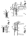
- FIG. 1 there is shown a cab 1 having a roof 2.
- a filter container 3 is removably mounted in the roof 2, access to the container being provided by hatch 10.
- Hatch 10 is pivotally attached to the structure of roof 2 of the cab 1, and can be moved from a closed position, as shown in Figure 2 , to an open position as shown in Figure 3 .
- the hatch 10 comprises a suitable fastener to fasten the hatch 10 in the position shown in Fig 2 .
- the container 3 consists of five sides, the top being completely open in order that the filter 7 may be freely placed in and removed from the container 3.
- the base and one side of the container are continuous, whilst the continuity of one side and one of the ends are interrupted by openings 6.
- the openings 6 provide pathways for air to be drawn from outside through the elements 8 of the filter 7 and into the cab. Also, air from the cab may be re-circulated from the cab, through the filter and back to the cab.
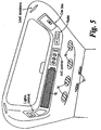
- FIGs 2 and 5 illustrate the path taken by fresh air drawn in from outside the cab.
- the roof 2 of the cab 1 comprises an air inlet 12. Air is drawn through the inlet and through the elements 8 of the filter 7, the filtered air egressing the filter through the top 9, which comprises suitable apertures. The filtered air passes through ducting and, if required, the air conditioning unit before entering the cab 1 through vents 13 and 14.
- the cab comprises a recirculation door 15. When the driver wishes to recirculate the air in the cab, rather than drawing in fresh air from outside the cab, air is drawn through the grille 15 and via filter 7 back into the cab through vents 13, 14.
- Rails 11 are mounted inside the roof. As can be seen from Figure 3 , the ends of the upper and lower rails 11 are bent in order to facilitate insertion and removal of the filter container 3 from the roof.
- the filter container 3 comprises bosses 5 on opposite sides of the container.
- the bosses 5 are substantially circular and are of diameter slightly less than the distance between the upper and lower rails 11 measured in the vertical direction, thereby providing a sliding fit between the bosses 5 and the rails 11.
- the rails 11 may be formed by plastics mouldings.
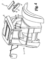
- the ends of the rail 11 proximal the hatch 10 comprise indents 17 into which the bosses 5 may drop, thereby permitting the container 3 to brought into a position where the end of the container distal from the bosses 5 is lower than said bosses, without the container being detached from the cab (see Figure 4 ).
- This feature facilitates emptying because the operator does not need to hold both ends of the container whilst removing and/or replacing the filter cartridge.
- Figure 2 shows that when the container 3 complete with the filter 7 is inserted into the roof of the cab, the filter 7 is held in place by frame members 16 which press down on the top 9 of the filter thereby preventing upward movement of the filter 7. This ensures that air entering the container 3 via the fresh air inlet and air intake holes 6 in the container 3 may only pass into the cab through the top 9 of the filter 7 as shown by the arrow "a" in Figure 2 . Absent a seal between the container 3 and the top 9 of the filter 7 air could pass into the cab without passing through the filter.
- the height x of the end of container 3 closest to the hatch 10 is greater than the height y of the end of the container 3 distal from the hatch. Hence, the base of the container 3 is at a slight angle to the horizontal, falling towards the hatch 10.
- the vibrations are transmitted, albeit in attenuated form, to the driver's cab 1.
- the vibrations cause the dust filtered from air passing through the filter element 8 to move towards the end of the container closest to the hatch 10.
- the rails 11 may be mounted in the roof 2 of the cab such that they are at a slight angle to the horizontal, thereby disposing the container 3 at a slight angle to the horizontal.
- the recess into which the container 3 slides is located just above the door which gives access to the operator's cab. Placing the filter in this position renders changing and/or cleaning the element an easy task.
- the operator opens the hatch 10, grips the handle 4 and pulls the container 3, with the filter 7, out of the recess.
- the bosses 5 locate in indents in the slides, and the container 3 is allowed to pivot downwards into the position shown in Figure 4 .
- the operator may then remove the filter 7 for cleaning or replacement. Dust accumulated in the container will fall out of the container through the opening 6 in the end of the container.
- the container 3 may be completely removed from the recess by lifting it out of the indents.
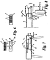
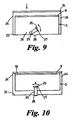
- FIG. 6 A second embodiment of the invention is illustrated in Figures 6 to 10 . Where appropriate, like numerals are used to reference like parts.
- the filter container 3 is similar to that of the first embodiment. However, it is of simpler design, insofar as the sides 20 do not comprise bosses or wheels extending therefrom.
- the roof 2 of the operator's cab comprises a chamber defined by an end wall 22, a floor 23, and sides 24.
- the chamber includes frame members 16 extending across the upper part of the chamber.
- the top 9 of the filter element presses upwardly against the frame members 16, which resist the upward force to securely fasten the filter element in position in the filter container 3.
- the frame members could be replaced by other structures against which the filter element may be pressed, for example the chamber may comprise a substantially flat ceiling formed for a material having sufficient stiffness to resist the upward force exerted by the filter element.
- a locking arrangement comprises a cam member 25 rotatably mounted on to the filter container 3 by a pin 26.
- a handle 26 is attached to the cam member 25. By gripping the handle 26 an operator can rotate the cam member 25 in the direction indicated by the arrow "z". The operator can also grip the handle to withdraw the container 3 from or insert the container 3 into the chamber.
- the hatch 10 shown in Figures 6 to 8 functions in the same manner as the hatch 10 shown in Figures 1 to 3 .
- the floor of the filter container 3 is set a slight angle below the horizontal so the dust and debris settles towards the end of the filter container 3 proximal the hatch 10.
- the invention provides for easy access to the filter, and for the filter to be held in the container as it is extended from the cab.
- the container collects any dust falling from the filter both prior to and during removal of the filter element.
- the potential for exposure of the vehicle operator to dust during the cleaning and/or replacement of the filter is much reduced by this invention.
Landscapes
- Engineering & Computer Science (AREA)
- Mechanical Engineering (AREA)
- Physics & Mathematics (AREA)
- Thermal Sciences (AREA)
- Air-Conditioning For Vehicles (AREA)
- Filtering Of Dispersed Particles In Gases (AREA)
- Air Filters, Heat-Exchange Apparatuses, And Housings Of Air-Conditioning Units (AREA)
Claims (13)
- Cabine de conduite de véhicule (1) comprenant un espace fermé pour le conducteur, la cabine comportant un dispositif de filtration d'air comprenant une chambre située au-dessus de l'espace fermé et contenant un conteneur de filtre amovible (3) comportant une base, quatre côtés, et au moins une ouverture d'entrée d'air ainsi qu'au moins une ouverture de sortie d'air (6), dans laquelle la ou chacune des ouvertures d'entrée d'air (6) est située sur les côtés du conteneur, la chambre comportant une entrée d'air et une sortie d'air, un filtre (7) contenu dans le conteneur de filtre, dans laquelle le filtre (7) est glissé hors de la chambre dans le conteneur (3) à partir d'une position de filtrage dans la chambre vers une position de vidage, dans laquelle lorsque le conteneur (3) est dans la position de vidage, l'élément de filtrage (7) peut être retiré du conteneur et le conteneur vidé de débris, et dans laquelle lorsque le conteneur (3) est dans la position de filtrage lesdites ouvertures sont positionnées entre l'entrée d'air et la sortie d'air de la chambre de telle sorte que l'air peut être aspiré à travers le filtre dans la cabine, le dispositif étant caractérisé en ce que
la position de vidage est à l'extérieur de la cabine et une trappe (10) fixée sur l'extérieur d'une structure de toit de la cabine est agencée de manière à fermer la chambre. - Cabine selon la revendication 1, qui comporte un agencement de verrouillage destiné à verrouiller le conteneur de filtrage (3) dans la position de filtrage.
- Cabine selon la revendication 2, dans laquelle l'agencement de verrouillage comprend une came (23) montée de manière à pouvoir pivoter sur le conteneur (3) et pouvant pivoter entre une position de verrouillage de conteneur de filtrage dans laquelle la came est couplée à la chambre (28) et une position de libération conteneur de filtrage dans laquelle la came est découplée de la chambre.
- Cabine selon la revendication 3, dans laquelle la chambre (3) comporte une découpe (28), la came (25) étant couplée à la découpe dans la position de verrouillage.
- Cabine selon l'une quelconque des revendications précédentes, dans laquelle le conteneur (3) comprend une poignée (4, 26) afin de faciliter le retrait de la chambre.
- Cabine selon la revendication 5, lorsqu'elle dépend de la revendication 3 ou 4, dans laquelle ladite poignée (26) est fixée sur ladite came (25).
- Cabine selon la revendication 1, dans laquelle la chambre comporte une paire de coulisseaux espacés horizontalement (11), chaque coulisseau comprenant une paire de rails espacés verticalement avec un élément formant bossage (5) respectif sur le conteneur qui coulisse entre chaque paire de rails respective.
- Cabine selon l'une quelconque des revendications précédentes, dans laquelle la partie supérieure de la chambre comprend au moins un élément (16) agencé afin d'exercer un effort vers le bas sur la partie supérieure de l'élément de filtrage (7) lorsque le conteneur (3) est dans sa position de filtrage.
- Cabine selon la revendication 8, dans laquelle la chambre comprend une paire d'éléments séparés l'un de l'autre (16) espacés et situés de telle sorte que le conteneur (3) et l'élément de filtrage (7) étant dans la position de filtrage, les éléments (16) exercent un effort vers le bas sur la surface supérieure de l'élément de filtrage, sensiblement sur son périmètre.
- Cabine selon l'une quelconque des revendications précédentes, dans laquelle la chambre s'étend dans le toit (2) de la cabine de conduite (1) dans une direction sensiblement perpendiculaire à la direction longitudinale du véhicule.
- Cabine selon l'une quelconque des revendications précédentes, dans laquelle la base du conteneur de filtrage (3) est inclinée vers le bas, vers l'extrémité de la chambre la plus proche de la trappe (10).
- Cabine selon la revendication 7, dans laquelle le coulisseau (5) comporte un moyen formant pivot, qui permet au conteneur (3) de pivoter vers le bas lorsqu'il est retiré de la chambre.
- Cabine selon la revendication 12, dans laquelle le moyen formant pivot comprend des découpes (17) sur les coulisseaux (11), et dans laquelle chaque élément formant bossage (5) est positionné dans sa découpe de coulisseau (17) respective lorsque le conteneur est retiré de la chambre afin de permettre le pivotement du conteneur vers le bas.
Applications Claiming Priority (2)
| Application Number | Priority Date | Filing Date | Title |
|---|---|---|---|
| GB0125694A GB2381216B (en) | 2001-10-26 | 2001-10-26 | Air conditioning filter |
| GB0125694 | 2001-10-26 |
Publications (3)
| Publication Number | Publication Date |
|---|---|
| EP1306249A2 EP1306249A2 (fr) | 2003-05-02 |
| EP1306249A3 EP1306249A3 (fr) | 2004-01-07 |
| EP1306249B1 true EP1306249B1 (fr) | 2012-05-02 |
Family
ID=9924556
Family Applications (1)
| Application Number | Title | Priority Date | Filing Date |
|---|---|---|---|
| EP02023367A Expired - Lifetime EP1306249B1 (fr) | 2001-10-26 | 2002-10-18 | Filtre pour une installation de climatisation |
Country Status (4)
| Country | Link |
|---|---|
| US (1) | US6878176B2 (fr) |
| EP (1) | EP1306249B1 (fr) |
| AT (1) | ATE555931T1 (fr) |
| GB (1) | GB2381216B (fr) |
Families Citing this family (8)
| Publication number | Priority date | Publication date | Assignee | Title |
|---|---|---|---|---|
| US7258715B2 (en) * | 2004-07-22 | 2007-08-21 | Kaz, Incorporated | Air cleaner |
| US8376820B2 (en) * | 2004-08-26 | 2013-02-19 | Caterpillar Inc. | Fender-accessible air filter |
| FR2908159B1 (fr) * | 2006-11-07 | 2009-01-23 | Mark Iv Systemes Moteurs Soc P | Dispositif de filtre a air a tiroir et ensemble d'admission comprenant un tel dispositif |
| BR102015015456B1 (pt) * | 2015-06-25 | 2023-02-28 | Marcopolo S.A | Sistema de troca de elemento filtrante em retorno de sistemas de ventilação, aparelho de ar condicionado dotado dito sistema de troca de elemento filtrante e veículo compreendendo o mesmo |
| KR101734734B1 (ko) * | 2015-12-31 | 2017-05-11 | 현대자동차주식회사 | 정비 편의성을 증대한 서랍식 에어클리너와 흡기시스템 및 차량 |
| KR102249595B1 (ko) * | 2017-05-16 | 2021-05-10 | 현대자동차 주식회사 | 차량용 에어 클리너 유닛 |
| DE102017115125A1 (de) * | 2017-07-06 | 2019-01-10 | Claas Selbstfahrende Erntemaschinen Gmbh | Kabinendach einer Kabine für ein landwirtschaftliches Arbeitsfahrzeug |
| US12491460B2 (en) * | 2021-09-30 | 2025-12-09 | Carrier Corporation | Duct mounted filtering apparatus |
Family Cites Families (15)
| Publication number | Priority date | Publication date | Assignee | Title |
|---|---|---|---|---|
| US3823532A (en) * | 1973-11-14 | 1974-07-16 | Combustion Eng | Filter |
| US4002443A (en) | 1975-03-31 | 1977-01-11 | Massey-Ferguson Inc. | Air filter clamping mechanism for cab |
| US4292060A (en) * | 1978-01-17 | 1981-09-29 | Aisin Sieki Kabushiki Kaisha | Air-filter assembly |
| US4140047A (en) * | 1978-04-07 | 1979-02-20 | Sperry Rand Corporation | Mobile cab with air filter |
| US4242951A (en) * | 1979-08-06 | 1981-01-06 | Cadillac Gage Company | Air intake vent for armored vehicle |
| US4251246A (en) * | 1980-01-24 | 1981-02-17 | Mine Safety Appliances Company | Safety device for side loading filtering apparatus |
| CA1176907A (fr) * | 1980-12-08 | 1984-10-30 | Allis-Chalmers Corporation | Filtre d'air jetable rabattable vers le bas pour habitacle de vehicule |
| IT1179369B (it) * | 1984-05-15 | 1987-09-16 | Ital Idee Srl | Gruppo filtrante multiplo, particolarmente per impianti di aerazione e condizionamento per autoveicoli e ambienti chiusi, munito di mezzi di controllo dell'efficienza |
| US4587890A (en) * | 1985-04-15 | 1986-05-13 | Sperry Corporation | Air filtration system for harvester operator cab |
| JP2528288B2 (ja) * | 1986-08-21 | 1996-08-28 | 本田技研工業株式会社 | 自動二輪車のエアクリ―ナ装置 |
| DE3643478A1 (de) * | 1986-12-19 | 1988-07-07 | Kloeckner Humboldt Deutz Ag | Luftfilterkasten fuer eine fahrerkabine |
| DE19543699C2 (de) * | 1995-11-23 | 1998-07-02 | Daimler Benz Ag | Belüftungsvorrichtung für Fahrzeuge |
| DE19628089C2 (de) * | 1996-07-12 | 1998-12-03 | Deere & Co | Belüftungseinrichtung für eine Fahrzeugkabine und Filtergehäuse |
| DE19638790A1 (de) * | 1996-09-21 | 1998-03-26 | Mann & Hummel Filter | Luftfilter |
| DE10034487A1 (de) * | 2000-07-15 | 2002-01-24 | Mhb Filtration Gmbh & Co Kg | Einschubfilter |
-
2001
- 2001-10-26 GB GB0125694A patent/GB2381216B/en not_active Expired - Lifetime
-
2002
- 2002-10-18 AT AT02023367T patent/ATE555931T1/de active
- 2002-10-18 EP EP02023367A patent/EP1306249B1/fr not_active Expired - Lifetime
- 2002-10-21 US US10/277,168 patent/US6878176B2/en not_active Expired - Lifetime
Also Published As
| Publication number | Publication date |
|---|---|
| GB2381216B (en) | 2005-05-11 |
| GB0125694D0 (en) | 2001-12-19 |
| US20030131572A1 (en) | 2003-07-17 |
| GB2381216A (en) | 2003-04-30 |
| US6878176B2 (en) | 2005-04-12 |
| ATE555931T1 (de) | 2012-05-15 |
| EP1306249A3 (fr) | 2004-01-07 |
| EP1306249A2 (fr) | 2003-05-02 |
Similar Documents
| Publication | Publication Date | Title |
|---|---|---|
| EP1100650B1 (fr) | Machine-outil a main pourvue d'un dispositif d'aspiration de poussiere | |
| DE69721271T2 (de) | Handstaubsauger | |
| CN1705451B (zh) | 吸尘器 | |
| EP2897513B1 (fr) | Aspirateur avec couvercle de batterie | |
| EP2637542B1 (fr) | Aspirateur | |
| CA2450058C (fr) | Aspirateur sans sac | |
| JPH04212619A (ja) | トラクタ運転台のための換気装置 | |
| WO1995027634A2 (fr) | Systeme de rangement, notamment pour parapluies, a monter dans une automobile | |
| US6878176B2 (en) | Air conditioning filter | |
| EP2825083B1 (fr) | Aspirateur a bain d'eau | |
| US4140047A (en) | Mobile cab with air filter | |
| JPH04215519A (ja) | 自動車内部空間用の暖房装置または空気調節装置 | |
| CN114699028B (zh) | 清洁基站 | |
| EP4258965B1 (fr) | Appareil nettoyeur avec dispositf de batterie et dispositif de nettoyage de filtre | |
| US5302153A (en) | Air filtering device for a motor vehicle | |
| EP0198543A2 (fr) | Système de filtration de l'air pour cabine d'opérateur | |
| DE19942483C1 (de) | Staubsauger, insbesondere Bodenstaubsauger mit einer Staubbeutelhalterung | |
| US11684048B2 (en) | Water filter for an aquarium | |
| AU2004202719B2 (en) | Vacuum cleaner | |
| EP0140234B1 (fr) | Aspirateur de poussières | |
| DE3537937C2 (de) | Staubsauger, insbesondere Bodenstaubsauger | |
| CN221044882U (zh) | 可移动式吸尘装置 | |
| DE3723148A1 (de) | Schmutzsaugerentsorgung | |
| JPH061764U (ja) | エンジン用のエアクリーナ | |
| EP4072389B1 (fr) | Dispositif d'aspiration, en particulier aspirateur |
Legal Events
| Date | Code | Title | Description |
|---|---|---|---|
| PUAI | Public reference made under article 153(3) epc to a published international application that has entered the european phase |
Free format text: ORIGINAL CODE: 0009012 |
|
| AK | Designated contracting states |
Designated state(s): AT BE BG CH CY CZ DE DK EE ES FI FR GB GR IE IT LI LU MC NL PT SE SK TR |
|
| AX | Request for extension of the european patent |
Extension state: AL LT LV MK RO SI |
|
| PUAL | Search report despatched |
Free format text: ORIGINAL CODE: 0009013 |
|
| AK | Designated contracting states |
Kind code of ref document: A3 Designated state(s): AT BE BG CH CY CZ DE DK EE ES FI FR GB GR IE IT LI LU MC NL PT SE SK TR |
|
| AX | Request for extension of the european patent |
Extension state: AL LT LV MK RO SI |
|
| RIC1 | Information provided on ipc code assigned before grant |
Ipc: 7B 60H 3/00 A Ipc: 7B 60H 3/06 B Ipc: 7B 60H 1/00 B |
|
| 17P | Request for examination filed |
Effective date: 20040130 |
|
| AKX | Designation fees paid |
Designated state(s): AT DE FI FR GB IT |
|
| 17Q | First examination report despatched |
Effective date: 20071102 |
|
| GRAP | Despatch of communication of intention to grant a patent |
Free format text: ORIGINAL CODE: EPIDOSNIGR1 |
|
| GRAS | Grant fee paid |
Free format text: ORIGINAL CODE: EPIDOSNIGR3 |
|
| GRAA | (expected) grant |
Free format text: ORIGINAL CODE: 0009210 |
|
| AK | Designated contracting states |
Kind code of ref document: B1 Designated state(s): AT DE FI FR GB IT |
|
| REG | Reference to a national code |
Ref country code: GB Ref legal event code: FG4D |
|
| REG | Reference to a national code |
Ref country code: AT Ref legal event code: REF Ref document number: 555931 Country of ref document: AT Kind code of ref document: T Effective date: 20120515 |
|
| REG | Reference to a national code |
Ref country code: DE Ref legal event code: R096 Ref document number: 60242785 Country of ref document: DE Effective date: 20120621 |
|
| PG25 | Lapsed in a contracting state [announced via postgrant information from national office to epo] |
Ref country code: FI Free format text: LAPSE BECAUSE OF FAILURE TO SUBMIT A TRANSLATION OF THE DESCRIPTION OR TO PAY THE FEE WITHIN THE PRESCRIBED TIME-LIMIT Effective date: 20120502 |
|
| REG | Reference to a national code |
Ref country code: AT Ref legal event code: MK05 Ref document number: 555931 Country of ref document: AT Kind code of ref document: T Effective date: 20120502 |
|
| PLBE | No opposition filed within time limit |
Free format text: ORIGINAL CODE: 0009261 |
|
| STAA | Information on the status of an ep patent application or granted ep patent |
Free format text: STATUS: NO OPPOSITION FILED WITHIN TIME LIMIT |
|
| PGFP | Annual fee paid to national office [announced via postgrant information from national office to epo] |
Ref country code: AT Payment date: 20121011 Year of fee payment: 11 |
|
| 26N | No opposition filed |
Effective date: 20130205 |
|
| REG | Reference to a national code |
Ref country code: DE Ref legal event code: R097 Ref document number: 60242785 Country of ref document: DE Effective date: 20130205 |
|
| PGFP | Annual fee paid to national office [announced via postgrant information from national office to epo] |
Ref country code: GB Payment date: 20141021 Year of fee payment: 13 |
|
| PGFP | Annual fee paid to national office [announced via postgrant information from national office to epo] |
Ref country code: IT Payment date: 20141028 Year of fee payment: 13 |
|
| REG | Reference to a national code |
Ref country code: FR Ref legal event code: PLFP Year of fee payment: 14 |
|
| GBPC | Gb: european patent ceased through non-payment of renewal fee |
Effective date: 20151018 |
|
| PG25 | Lapsed in a contracting state [announced via postgrant information from national office to epo] |
Ref country code: GB Free format text: LAPSE BECAUSE OF NON-PAYMENT OF DUE FEES Effective date: 20151018 Ref country code: IT Free format text: LAPSE BECAUSE OF NON-PAYMENT OF DUE FEES Effective date: 20151018 |
|
| PG25 | Lapsed in a contracting state [announced via postgrant information from national office to epo] |
Ref country code: AT Free format text: THE PATENT HAS BEEN ANNULLED BY A DECISION OF A NATIONAL AUTHORITY Effective date: 20120502 |
|
| REG | Reference to a national code |
Ref country code: FR Ref legal event code: PLFP Year of fee payment: 15 |
|
| REG | Reference to a national code |
Ref country code: FR Ref legal event code: PLFP Year of fee payment: 16 |
|
| REG | Reference to a national code |
Ref country code: FR Ref legal event code: PLFP Year of fee payment: 17 |
|
| PGFP | Annual fee paid to national office [announced via postgrant information from national office to epo] |
Ref country code: DE Payment date: 20211020 Year of fee payment: 20 |
|
| PGFP | Annual fee paid to national office [announced via postgrant information from national office to epo] |
Ref country code: FR Payment date: 20211021 Year of fee payment: 20 |
|
| REG | Reference to a national code |
Ref country code: DE Ref legal event code: R071 Ref document number: 60242785 Country of ref document: DE |