EP1306337A1 - Moyen de pression réglable pour empileur - Google Patents
Moyen de pression réglable pour empileur Download PDFInfo
- Publication number
- EP1306337A1 EP1306337A1 EP02023784A EP02023784A EP1306337A1 EP 1306337 A1 EP1306337 A1 EP 1306337A1 EP 02023784 A EP02023784 A EP 02023784A EP 02023784 A EP02023784 A EP 02023784A EP 1306337 A1 EP1306337 A1 EP 1306337A1
- Authority
- EP
- European Patent Office
- Prior art keywords
- paddle
- stack
- urging
- force
- pulley
- Prior art date
- Legal status (The legal status is an assumption and is not a legal conclusion. Google has not performed a legal analysis and makes no representation as to the accuracy of the status listed.)
- Granted
Links
- 238000006073 displacement reaction Methods 0.000 description 4
- 229910000831 Steel Inorganic materials 0.000 description 1
- 238000009825 accumulation Methods 0.000 description 1
- 230000006835 compression Effects 0.000 description 1
- 238000007906 compression Methods 0.000 description 1
- 230000000694 effects Effects 0.000 description 1
- 238000001228 spectrum Methods 0.000 description 1
- 239000010959 steel Substances 0.000 description 1
Images


Classifications
-
- B—PERFORMING OPERATIONS; TRANSPORTING
- B65—CONVEYING; PACKING; STORING; HANDLING THIN OR FILAMENTARY MATERIAL
- B65H—HANDLING THIN OR FILAMENTARY MATERIAL, e.g. SHEETS, WEBS, CABLES
- B65H31/00—Pile receivers
- B65H31/04—Pile receivers with movable end support arranged to recede as pile accumulates
- B65H31/06—Pile receivers with movable end support arranged to recede as pile accumulates the articles being piled on edge
-
- B—PERFORMING OPERATIONS; TRANSPORTING
- B65—CONVEYING; PACKING; STORING; HANDLING THIN OR FILAMENTARY MATERIAL
- B65H—HANDLING THIN OR FILAMENTARY MATERIAL, e.g. SHEETS, WEBS, CABLES
- B65H2402/00—Constructional details of the handling apparatus
- B65H2402/50—Machine elements
- B65H2402/54—Springs, e.g. helical or leaf springs
-
- B—PERFORMING OPERATIONS; TRANSPORTING
- B65—CONVEYING; PACKING; STORING; HANDLING THIN OR FILAMENTARY MATERIAL
- B65H—HANDLING THIN OR FILAMENTARY MATERIAL, e.g. SHEETS, WEBS, CABLES
- B65H2403/00—Power transmission; Driving means
- B65H2403/70—Clutches; Couplings
- B65H2403/72—Clutches, brakes, e.g. one-way clutch +F204
-
- B—PERFORMING OPERATIONS; TRANSPORTING
- B65—CONVEYING; PACKING; STORING; HANDLING THIN OR FILAMENTARY MATERIAL
- B65H—HANDLING THIN OR FILAMENTARY MATERIAL, e.g. SHEETS, WEBS, CABLES
- B65H2515/00—Physical entities not provided for in groups B65H2511/00 or B65H2513/00
- B65H2515/30—Forces; Stresses
-
- B—PERFORMING OPERATIONS; TRANSPORTING
- B65—CONVEYING; PACKING; STORING; HANDLING THIN OR FILAMENTARY MATERIAL
- B65H—HANDLING THIN OR FILAMENTARY MATERIAL, e.g. SHEETS, WEBS, CABLES
- B65H2701/00—Handled material; Storage means
- B65H2701/10—Handled articles or webs
- B65H2701/19—Specific article or web
- B65H2701/1916—Envelopes and articles of mail
Definitions
- the present invention relates generally to a mail or document stacking machine and, more particularly, to a stack support for providing a resisting force to the stack as the mailpiece or document is accumulated into the stack.
- a paddle or an abutment member, is used to support the stack while allowing the stack thickness to increase.
- a resisting force is usually provided to the paddle against the stack.
- the paddle 40 is slidably mounted on a shaft or bar 32 by means of a cylindrical shaped member 34 .
- the cylindrical shaped member 34 is spring-loaded to provide a resisting force 150 to the paddle 40 as the stack 100 is pushed in a direction 102 when the mailpiece 110 is accumulated into the stack 100 by an input mechanism 90 , as shown in Figure 1.
- an input mechanism 90 As disclosed in U.S. Patent No. 4,524,965 ( Kulpa ), one end of a cord 54 is tied to the cylindrical shaped member 34 and the other end of the cord 54 is wrapped around a rotary displacement device 60 .
- the cylindrical member 34 along with the paddle 40 and the stack 100 , is pushed along the direction 102 , it causes the rotary displacement device 60 to rotate along a rotation direction 106 , as shown in Figure 2.
- a pulley 70 is fixedly mounted on the rotary displacement device 60 for motion.
- One end of another cord 52 is wrapped around the pulley 70 and the other end of the cord 52 is tied to a spring 50 .
- the rotary displacement device 60 When the rotary displacement device 60 is rotated along the rotation direction 106 , it causes the spring 50 is stretched along the direction 104 . As the spring 50 is stretched, it increases the tension 202 in the cord 52 , thereby increasing the resistance force 150 provided to the paddle 40 .
- the resisting force providing systems are useful in supporting a stack of mailpieces as the thickness of the stack increases, the resisting force cannot be adjusted according to the load of the mailpieces. On the one hand, if the resistance force is too high, then lightweight mailpieces may be damaged when they are accumulated into the stack. On the other hand, if the resistance force is too low, the stack may overpower the paddle and cause the entire stack to topple over.
- a paddle urging system for use in a stacking bin having a first end and an opposing second end, wherein a paddle is provided in the stacking bin to support a stack of mailpieces in the stacking bin and wherein the mailpieces are accumulated into the stack at the first end of the stacking bin, thereby increasing the thickness of the stack and pushing the stack against the paddle in a first direction toward the second end of the stacking bin, said paddle system comprising:
- the urging mechanism comprises a spring, connected to the paddle by a flexible member, for providing the urging force to the paddle.
- the adjustable resisting force mechanism comprises a clutch system for providing the resisting force, and the flexible member is mechanically engaged with the clutch system for conveying the resisting force provided by the clutch to the paddle.
- the clutch system comprises a pulley engaged with a one-way clutch such that the pulley is allowed to turn in a first rotation direction with respect to a rotation axis and the pulley is prevented from turning in a second rotation direction opposite from the first rotation direction, and wherein the one-way clutch is further engaged with a rotating member with an adjustable friction force and the rotating member is disposed axially with the rotation axis, such that when the pulley is caused to turn in the second rotation direction by the pushing of the stack toward the second end of the stacking bin, the one-way clutch causes the rotating member to rotate against the friction force for providing the resisting force to the flexible member, and when the pulley is caused to turn in the first rotation direction, the one-way clutch and the rotating member are effectively disengaged from the pulley.
- a stacking bin for use in a mail processing machine for accumulating mailpieces into a stack from a first end of the stack, wherein the stack is pushed toward a first direction when the mailpieces are accumulated into the stack, thereby increase the thickness of the stack and pushing the stack along a first direction, said stacking bin comprising:
- Figure 1 is a diagrammatic representation showing the top view of a prior art stacking bin.
- Figure 2 is a diagrammatic representation showing the top view of another prior art stacking bin.
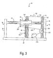
- Figure 3 is a diagrammatic representation showing a side view of the stacking bin, according to the present invention.
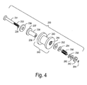
- Figure 4 is an exploded view of the adjustable resisting force mechanism, according to the present invention.
- a stacking bin 10 has a platform 20 to support a stack 100 of mailpieces 110 .
- the stacking bin 10 has a first end 12 and an opposing second end 14
- the stack 100 has a first end 122 and an opposing second end 124 .
- a paddle 40 is provided at the second end 124 of the stack 100 for supporting the stack 100 .
- the thickness of the stack 100 increases and the stack 100 is pushed toward the second end 14 along a direction 102 .
- a shaft 32 is mounted on the platform 20 by means of shaft mounts 30 .
- a sleeve or cylindrical shaped member 34 is slidably mounted on the shaft 32 and a paddle 40 is mechanically connected to the cylindrical shaped member 34 so that the paddle 40 is moved when the cylindrical shaped member 34 is moved along the shaft 32 .
- a spring 210 preferably a constant force spring, mounted on the platform 20 , is used to provide an urging force 150 to the paddle 40 via a cord 220 (or a steel cable) and the like.
- An adjustable resisting force mechanism 230 is operatively connected to the spring 210 to provide an additional force to the paddle when the paddle is pushed toward the second end 14 of the stacking bin 10 as the mailpieces 110 are accumulated into the stack 100 .
- the adjustable resisting force mechanism 230 has a one-way clutch, which produces a friction force only when the resisting force mechanism 230 is caused to rotate along a rotation direction 232 . There is no significant friction force when the resisting force mechanism 230 is caused to rotate in a direction opposite from the direction 232 .
- the resistance force 150 provided to the paddle 40 is substantially equal to the tension force of the spring 210 , reduced by the friction force between the cylindrical shaped member 34 and the shaft 32 , and some small friction force in the resisting force mechanism 230 .
- the paddle 40 is automatically retracted to the first end 12 .
- Figure 4 shows the preferred embodiment of the resisting force mechanism 230 .
- the resisting force mechanism 230 comprises a brake shaft 231 for axially mounting a brake disk 236 , a brake hub 238 , a pulley/clutch assembly 240 , a thrust washer 252 , a washer 254 , a spring 256 , washer 258 , an adjustment knob 262 and a retaining ring 264 .
- the pulley/clutch assembly 240 consists of a pulley 242 and a one-way clutch 250 .
- the pulley 242 has an outer periphery 243 , around which the cord 220 is wrapped about 1.5 turns for engaging the resisting force mechanism 230 with the paddle 40 .
- the brake shaft 232 has a threaded front section 233 to allow the adjustment knob 262 to screw thereon.
- the lock washer 264 is pushed onto the tip 234 of the threaded section 233 to prevent the adjustment knob 262 from being mechanically disengaged from the brake shaft 232 .
- a one-way bearing 250 is mounted on the inner periphery 244 of the pulley 242 for engaging with the brake hub 238 .
- the one-way clutch 250 allows the brake hub 238 to rotate against the pulley 240 in a direction, with respect to a rotation axis defined by the longitudinal axis of the brake shaft 232 , but prevents the brake hub 238 from doing so in the opposite direction.
- the thrust washer 252 When these components are assembled, the thrust washer 252 is in direct contact with the front end 239 of the brake hub 238 , the brake disk 236 is in direct contact with the rear end 237 of the brake hub 238 , and the adjustment knob 262 compresses the spring 256 . As such, the spring 256 creates a clamping force between the thrust washer 252 , the brake hub 238 and the brake disk 236 . The clamping force is adjustable by adjusting the adjustment knob 262 against the spring 256 . As mailpieces 110 are accumulated into the stack 100 , the movement of the paddle 40 causes the pulley 242 to rotate.
- the rotation of the pulley 242 causes the one-way clutch 250 to engage the brake hub 238 , causing it to turn along with the pulley 242 .
- the brake hub 238 turns, its motion is resisted by the clamping force, resulting in an addition drag on the entire paddle urging system.
- the additional drag increases the force required to move the paddle 40 towards the second end 14 .
- the end effect is that heavy mailpieces are supported more effectively.
- the one-way clutch 250 overruns, allowing the paddle 40 to return to its home position near the first end 12 without having to overcome the drag provided by the resisting force mechanism 230 .
- the spring 256 is not compressed and the clamping force between the thrust washer 252 , the brake hub 238 and the brake disk 236 does not produce any significant additional drag.
- the force seen at the paddle 40 is mainly the tension force provided by the constant force spring 210 . This setting can be used for mailpieces that are on the lower end of the weight spectrum.
- the advantage of the paddle urging system which comprises the constant force spring 210 and the resisting force mechanism 230 , is that it allows the operator to easily adjust the resistance force 150 to an optimal level according to a particular type of mailpiece weight.
- the adjustment knob 262 is turned to a particular setting, the force provided to the paddle 40 remains relatively constant over the full travel of the paddle between the first end 12 and the second end 14 of the stacking bin 10 .
- a simple torsion or extension spring normally exhibits a relatively high spring rate, which would cause the paddle force to increase as the stack fills.
- the present invention allows a mail sorter operator to adjust the paddle's normal force according to the weight of the mailpieces being handled.
- the present invention uses a constant force spring 210 as an urging mechanism for providing an initial paddle force and to provide the force required to retract the paddle after the stack has been emptied.
- a brake/clutch assembly and a compression spring are used as an adjustable resisting force mechanism for providing a drag when the mailpieces are accumulated into a mail stack.
- the cord 220 is wrapped around the pulley 242 to engage the adjustable resisting force mechanism 230 with the constant force spring 210 .
- the adjustable resisting force mechanism 230 is operatively connected to the paddle 40 , separately from the constant force spring 210 .
Landscapes
- Engineering & Computer Science (AREA)
- Mechanical Engineering (AREA)
- Pile Receivers (AREA)
Applications Claiming Priority (2)
| Application Number | Priority Date | Filing Date | Title |
|---|---|---|---|
| US3452 | 1998-01-06 | ||
| US10/003,452 US6588743B2 (en) | 2001-10-25 | 2001-10-25 | Adjustable urging force system for stacker paddle |
Publications (2)
| Publication Number | Publication Date |
|---|---|
| EP1306337A1 true EP1306337A1 (fr) | 2003-05-02 |
| EP1306337B1 EP1306337B1 (fr) | 2005-08-24 |
Family
ID=21705941
Family Applications (1)
| Application Number | Title | Priority Date | Filing Date |
|---|---|---|---|
| EP02023784A Expired - Lifetime EP1306337B1 (fr) | 2001-10-25 | 2002-10-25 | Moyen de pression réglable pour empileur |
Country Status (4)
| Country | Link |
|---|---|
| US (1) | US6588743B2 (fr) |
| EP (1) | EP1306337B1 (fr) |
| CA (1) | CA2409381C (fr) |
| DE (1) | DE60205699T2 (fr) |
Cited By (3)
| Publication number | Priority date | Publication date | Assignee | Title |
|---|---|---|---|---|
| WO2013083893A1 (fr) | 2011-12-05 | 2013-06-13 | Solystic | Dispositif d'empilage pour objets plats empilés sur chant et machine de tri postal |
| EP2607277A1 (fr) | 2011-12-23 | 2013-06-26 | Neopost Technologies | Système d'amélioration de l'empilage d'articles plats |
| EP2781479B1 (fr) * | 2013-03-21 | 2017-12-13 | Kabushiki Kaisha Toshiba | Appareil d'empilage de feuilles de papier |
Families Citing this family (10)
| Publication number | Priority date | Publication date | Assignee | Title |
|---|---|---|---|---|
| DE10043206C1 (de) * | 2000-09-01 | 2002-02-07 | Siemens Ag | Stapelvorrichtung für flache, auf ihren Schmalseiten stehende Sendungen |
| DE10060178A1 (de) * | 2000-12-04 | 2002-06-20 | Siemens Ag | Stapeleinrichtung für flache Stapelelemente |
| DE10223349B4 (de) * | 2002-05-25 | 2004-07-01 | Siemens Ag | Verfahren und Einrichtung zum Stapeln von flachen Sendungen |
| US6997454B2 (en) * | 2002-12-17 | 2006-02-14 | Pitney Bowes Inc. | Paddle and paddle support in on-edge mail stackers |
| US7028580B2 (en) * | 2002-12-17 | 2006-04-18 | Xerox Corporation | Rotational cable shortening device |
| TWI229653B (en) * | 2003-11-13 | 2005-03-21 | Primax Electronics Ltd | Paper-pickup force adjusting mechanism |
| DE102004012379B4 (de) * | 2004-03-13 | 2006-01-19 | Siemens Ag | Verfahren und Einrichtung zum Stapeln von flachen Sendungen |
| US7237773B1 (en) * | 2004-05-27 | 2007-07-03 | Unisys Corporation | System for feeding and transporting documents |
| US8590889B2 (en) * | 2011-05-02 | 2013-11-26 | Lexmark International, Inc. | Multi-translative roll assembly having a one-way clutching surface |
| CN112249416A (zh) * | 2020-11-18 | 2021-01-22 | 沙洲职业工学院 | 一种板材防倾排列打包装置 |
Citations (2)
| Publication number | Priority date | Publication date | Assignee | Title |
|---|---|---|---|---|
| US4524965A (en) * | 1984-01-25 | 1985-06-25 | Pitney Bowes Inc. | Envelope stacking machine |
| JPS62105859A (ja) * | 1985-10-29 | 1987-05-16 | Omron Tateisi Electronics Co | 紙葉類集積装置 |
Family Cites Families (7)
| Publication number | Priority date | Publication date | Assignee | Title |
|---|---|---|---|---|
| US4065123A (en) * | 1976-12-02 | 1977-12-27 | International Business Machines Corporation | Apparatus for stacking documents in sequence |
| NL8702786A (nl) * | 1987-11-20 | 1989-06-16 | Nederlanden Staat | Inrichting voor het stapelen van bladvormige voorwerpen zoals brieven. |
| US4953748A (en) * | 1988-08-23 | 1990-09-04 | Diebold, Incorporated | Force modifying device |
| DE69208029T2 (de) * | 1991-11-13 | 1996-05-30 | Fujitsu Ltd | Stapelhalter für Papier |
| US5221080A (en) * | 1992-02-18 | 1993-06-22 | Bell & Howell Company | Stacker assembly having variable pressure stacker plate |
| US5524876A (en) * | 1994-12-22 | 1996-06-11 | F. L. Smithe Machine Company, Inc. | Method and apparatus for delivering and stacking envelopes in an envelope machine |
| US6419221B1 (en) * | 2000-03-08 | 2002-07-16 | Unisys Corporation | Adaptive flag weight for document handling apparatus |
-
2001
- 2001-10-25 US US10/003,452 patent/US6588743B2/en not_active Expired - Fee Related
-
2002
- 2002-10-23 CA CA002409381A patent/CA2409381C/fr not_active Expired - Fee Related
- 2002-10-25 DE DE60205699T patent/DE60205699T2/de not_active Expired - Lifetime
- 2002-10-25 EP EP02023784A patent/EP1306337B1/fr not_active Expired - Lifetime
Patent Citations (2)
| Publication number | Priority date | Publication date | Assignee | Title |
|---|---|---|---|---|
| US4524965A (en) * | 1984-01-25 | 1985-06-25 | Pitney Bowes Inc. | Envelope stacking machine |
| JPS62105859A (ja) * | 1985-10-29 | 1987-05-16 | Omron Tateisi Electronics Co | 紙葉類集積装置 |
Non-Patent Citations (1)
| Title |
|---|
| PATENT ABSTRACTS OF JAPAN vol. 011, no. 323 (M - 634) 21 October 1987 (1987-10-21) * |
Cited By (4)
| Publication number | Priority date | Publication date | Assignee | Title |
|---|---|---|---|---|
| WO2013083893A1 (fr) | 2011-12-05 | 2013-06-13 | Solystic | Dispositif d'empilage pour objets plats empilés sur chant et machine de tri postal |
| EP3070036A1 (fr) | 2011-12-05 | 2016-09-21 | Solystic | Dispositif d'empilage pour objets plats empiles sur chant et machine de tri postal correspondante |
| EP2607277A1 (fr) | 2011-12-23 | 2013-06-26 | Neopost Technologies | Système d'amélioration de l'empilage d'articles plats |
| EP2781479B1 (fr) * | 2013-03-21 | 2017-12-13 | Kabushiki Kaisha Toshiba | Appareil d'empilage de feuilles de papier |
Also Published As
| Publication number | Publication date |
|---|---|
| CA2409381C (fr) | 2007-06-26 |
| US6588743B2 (en) | 2003-07-08 |
| CA2409381A1 (fr) | 2003-04-25 |
| DE60205699D1 (de) | 2005-09-29 |
| DE60205699T2 (de) | 2006-06-08 |
| US20030080499A1 (en) | 2003-05-01 |
| EP1306337B1 (fr) | 2005-08-24 |
Similar Documents
| Publication | Publication Date | Title |
|---|---|---|
| US6588743B2 (en) | Adjustable urging force system for stacker paddle | |
| DE69502996T2 (de) | Bogen Vereinzelungs- und Zuführungssystem | |
| US4177982A (en) | Sheet feeders | |
| US6024356A (en) | Drive power transmission | |
| EP0866008B1 (fr) | Dispositif d'alimentation en supports d'information | |
| EP1517848A1 (fr) | Ensemble rouleaux pour un transporteur d'accumulation a rouleaux | |
| CN1146419A (zh) | 送纸装置和方法 | |
| US7513485B2 (en) | Automatic winder | |
| SE444657B (sv) | Beltessperranordning, serskilt for sekerhetsbelten i motorfordon | |
| EP1302421A2 (fr) | Dispositif d'alimentation en feuilles pour imprimante | |
| AU2001287069B2 (en) | High-Capacity output catch tray for document production machines | |
| US5362037A (en) | Method of, and apparatus for, delivering flat articles one by one from a stack of such articles | |
| US4052053A (en) | Stacker drum of sheet accumulating device | |
| US6585251B2 (en) | Articulating separator | |
| KR101292038B1 (ko) | 지엽류 분리 기구 및 그것을 이용한 지엽류 분리 집적기구 | |
| CA2005524A1 (fr) | Systeme d'alimentation pour ruban en rouleau | |
| EP1725486B1 (fr) | Procede et dispositif pour empiler des envois plats | |
| CN101610967A (zh) | 夹紧设备 | |
| US5318161A (en) | Wrap spring clutch assembly | |
| US6419221B1 (en) | Adaptive flag weight for document handling apparatus | |
| GB2132988A (en) | Means for braking a motor-driven reeling device | |
| CN212174121U (zh) | 一种包装带收卷机用张紧机构的输出张紧轮安装结构 | |
| EP1954612A1 (fr) | Procédé et système servant a extraire des feuilles d'extremité d'une pile de feuilles | |
| EP0761321B1 (fr) | Dispositif d'alimentation pour des envois postaux | |
| DE4101381A1 (de) | Vorrichtung zum stapelweisen ablegen und ausrichten von einzeln zugefuehrten blaettern |
Legal Events
| Date | Code | Title | Description |
|---|---|---|---|
| PUAI | Public reference made under article 153(3) epc to a published international application that has entered the european phase |
Free format text: ORIGINAL CODE: 0009012 |
|
| AK | Designated contracting states |
Designated state(s): AT BE BG CH CY CZ DE DK EE ES FI FR GB GR IE IT LI LU MC NL PT SE SK TR |
|
| AX | Request for extension of the european patent |
Extension state: AL LT LV MK RO SI |
|
| 17P | Request for examination filed |
Effective date: 20031029 |
|
| AKX | Designation fees paid |
Designated state(s): DE FR GB |
|
| 17Q | First examination report despatched |
Effective date: 20040624 |
|
| GRAP | Despatch of communication of intention to grant a patent |
Free format text: ORIGINAL CODE: EPIDOSNIGR1 |
|
| RAP1 | Party data changed (applicant data changed or rights of an application transferred) |
Owner name: PITNEY BOWES INC. |
|
| GRAS | Grant fee paid |
Free format text: ORIGINAL CODE: EPIDOSNIGR3 |
|
| GRAA | (expected) grant |
Free format text: ORIGINAL CODE: 0009210 |
|
| AK | Designated contracting states |
Kind code of ref document: B1 Designated state(s): DE FR GB |
|
| REG | Reference to a national code |
Ref country code: GB Ref legal event code: FG4D |
|
| REF | Corresponds to: |
Ref document number: 60205699 Country of ref document: DE Date of ref document: 20050929 Kind code of ref document: P |
|
| ET | Fr: translation filed | ||
| PLBE | No opposition filed within time limit |
Free format text: ORIGINAL CODE: 0009261 |
|
| STAA | Information on the status of an ep patent application or granted ep patent |
Free format text: STATUS: NO OPPOSITION FILED WITHIN TIME LIMIT |
|
| 26N | No opposition filed |
Effective date: 20060526 |
|
| PGFP | Annual fee paid to national office [announced via postgrant information from national office to epo] |
Ref country code: FR Payment date: 20091029 Year of fee payment: 8 |
|
| PG25 | Lapsed in a contracting state [announced via postgrant information from national office to epo] |
Ref country code: FR Free format text: LAPSE BECAUSE OF NON-PAYMENT OF DUE FEES Effective date: 20101102 |
|
| REG | Reference to a national code |
Ref country code: FR Ref legal event code: ST Effective date: 20110630 |
|
| PGFP | Annual fee paid to national office [announced via postgrant information from national office to epo] |
Ref country code: DE Payment date: 20141029 Year of fee payment: 13 Ref country code: GB Payment date: 20141027 Year of fee payment: 13 |
|
| REG | Reference to a national code |
Ref country code: DE Ref legal event code: R119 Ref document number: 60205699 Country of ref document: DE |
|
| GBPC | Gb: european patent ceased through non-payment of renewal fee |
Effective date: 20151025 |
|
| PG25 | Lapsed in a contracting state [announced via postgrant information from national office to epo] |
Ref country code: GB Free format text: LAPSE BECAUSE OF NON-PAYMENT OF DUE FEES Effective date: 20151025 Ref country code: DE Free format text: LAPSE BECAUSE OF NON-PAYMENT OF DUE FEES Effective date: 20160503 |