EP1306514B1 - Bremsvorrichtung für Jalousiezüge - Google Patents
Bremsvorrichtung für Jalousiezüge Download PDFInfo
- Publication number
- EP1306514B1 EP1306514B1 EP02021933A EP02021933A EP1306514B1 EP 1306514 B1 EP1306514 B1 EP 1306514B1 EP 02021933 A EP02021933 A EP 02021933A EP 02021933 A EP02021933 A EP 02021933A EP 1306514 B1 EP1306514 B1 EP 1306514B1
- Authority
- EP
- European Patent Office
- Prior art keywords
- guide
- braking device
- braking
- roller
- furniture
- Prior art date
- Legal status (The legal status is an assumption and is not a legal conclusion. Google has not performed a legal analysis and makes no representation as to the accuracy of the status listed.)
- Expired - Lifetime
Links
- 238000005096 rolling process Methods 0.000 claims description 5
- 230000006378 damage Effects 0.000 description 5
- 230000000694 effects Effects 0.000 description 4
- 208000027418 Wounds and injury Diseases 0.000 description 3
- 208000014674 injury Diseases 0.000 description 3
- 229920001296 polysiloxane Polymers 0.000 description 3
- 230000008439 repair process Effects 0.000 description 2
- 230000002950 deficient Effects 0.000 description 1
- 239000013013 elastic material Substances 0.000 description 1
- 239000004744 fabric Substances 0.000 description 1
- 239000000463 material Substances 0.000 description 1
- 238000000034 method Methods 0.000 description 1
- 229920002635 polyurethane Polymers 0.000 description 1
- 239000004814 polyurethane Substances 0.000 description 1
- 238000011084 recovery Methods 0.000 description 1
Images


Classifications
-
- E—FIXED CONSTRUCTIONS
- E06—DOORS, WINDOWS, SHUTTERS, OR ROLLER BLINDS IN GENERAL; LADDERS
- E06B—FIXED OR MOVABLE CLOSURES FOR OPENINGS IN BUILDINGS, VEHICLES, FENCES OR LIKE ENCLOSURES IN GENERAL, e.g. DOORS, WINDOWS, BLINDS, GATES
- E06B9/00—Screening or protective devices for wall or similar openings, with or without operating or securing mechanisms; Closures of similar construction
- E06B9/56—Operating, guiding or securing devices or arrangements for roll-type closures; Spring drums; Tape drums; Counterweighting arrangements therefor
- E06B9/80—Safety measures against dropping or unauthorised opening; Braking or immobilising devices; Devices for limiting unrolling
-
- E—FIXED CONSTRUCTIONS
- E06—DOORS, WINDOWS, SHUTTERS, OR ROLLER BLINDS IN GENERAL; LADDERS
- E06B—FIXED OR MOVABLE CLOSURES FOR OPENINGS IN BUILDINGS, VEHICLES, FENCES OR LIKE ENCLOSURES IN GENERAL, e.g. DOORS, WINDOWS, BLINDS, GATES
- E06B9/00—Screening or protective devices for wall or similar openings, with or without operating or securing mechanisms; Closures of similar construction
- E06B9/02—Shutters, movable grilles, or other safety closing devices, e.g. against burglary
- E06B9/08—Roll-type closures
- E06B9/11—Roller shutters
- E06B9/115—Roller shutters specially adapted for furniture
-
- E—FIXED CONSTRUCTIONS
- E06—DOORS, WINDOWS, SHUTTERS, OR ROLLER BLINDS IN GENERAL; LADDERS
- E06B—FIXED OR MOVABLE CLOSURES FOR OPENINGS IN BUILDINGS, VEHICLES, FENCES OR LIKE ENCLOSURES IN GENERAL, e.g. DOORS, WINDOWS, BLINDS, GATES
- E06B9/00—Screening or protective devices for wall or similar openings, with or without operating or securing mechanisms; Closures of similar construction
- E06B9/24—Screens or other constructions affording protection against light, especially against sunshine; Similar screens for privacy or appearance; Slat blinds
- E06B9/26—Lamellar or like blinds, e.g. venetian blinds
- E06B9/28—Lamellar or like blinds, e.g. venetian blinds with horizontal lamellae, e.g. non-liftable
- E06B9/30—Lamellar or like blinds, e.g. venetian blinds with horizontal lamellae, e.g. non-liftable liftable
- E06B9/32—Operating, guiding, or securing devices therefor
- E06B9/322—Details of operating devices, e.g. pulleys, brakes, spring drums, drives
-
- E—FIXED CONSTRUCTIONS
- E06—DOORS, WINDOWS, SHUTTERS, OR ROLLER BLINDS IN GENERAL; LADDERS
- E06B—FIXED OR MOVABLE CLOSURES FOR OPENINGS IN BUILDINGS, VEHICLES, FENCES OR LIKE ENCLOSURES IN GENERAL, e.g. DOORS, WINDOWS, BLINDS, GATES
- E06B9/00—Screening or protective devices for wall or similar openings, with or without operating or securing mechanisms; Closures of similar construction
- E06B9/56—Operating, guiding or securing devices or arrangements for roll-type closures; Spring drums; Tape drums; Counterweighting arrangements therefor
- E06B9/68—Operating devices or mechanisms, e.g. with electric drive
Definitions
- Rolling cabinets with jalousie pulls, also called roll cabinets, are today used in a variety of ways, especially in office facilities. Rolling cabinets have the advantage that they are very advantageous in terms of space requirements. They occupy the same space regardless of whether they are open or closed. Rolling cabinets are generally designed so that on the vertical sides of the cabinet grooves are formed in which move the blinds in such a way that the blinds move preferably up or down.
- the blinds are usually formed from rods, strips or the like and can be attached to the back of a uniform fabric or similar track.
- Venetian blinds and the corresponding grooves with them must be designed so that on the one hand, the grooves must be made so wide that the blind pull it easily and without much effort. On the other hand, the blind pull must not run too easily in the grooves, because otherwise it can fall on the fingers, for example, and thus cause injuries.
- Roller blinds have in roll cabinets, in which the blind pull is moved vertically, d. H. up or down, the disadvantage that they move unrestrained when opening or closing, which may cause a certain risk of injury to the user.
- This braking device is used for a cupboard door, the side edges are each guided in a channel / guide rail.
- the brake device is arranged on both sides of the cabinet inner wall on the guide rail / the channel.
- the brake elements of the brake device are each arranged eccentrically on a lever.
- This spring system ensures that the blind pulls easily into the groove without moving on release.
- the disadvantage of this solution is that on the one hand the spring system constructed very complicated and on the other hand, a double rear wall is required.
- Another possibility is to make the grooves relatively wide, to ensure the mobility of the blind pull, and to install in the groove a braking material (eg polyurethane) for braking the blind movement. Furthermore, it has been proposed to attach friction pins to certain bars of the blind pull, which run in the grooves and slow down the movement of the blind.
- a braking material eg polyurethane
- Brake devices of the type described above are conventionally made of cables attached to the ends of blind trains, which in turn are connected to a torsion spring and a locking body having locking or braking body, which preferably extends in the cabinet interior in the rear area across the furniture. These are very difficult to access in case of repairs, so that considerable work has to be carried out on the furniture itself in order to replace defective parts of the brake device or to repair them.
- a braking device that acts on the shutter pull is out of the DE 195 31 071 C1 known.
- the braking device described here consists of a brake body arranged in a housing, wherein the brake body is designed as a movable, from a locking in the braking direction brake operating position by an engageable with the blind pull actuator in a release position convertible brake shoe. Due to the movable arrangement of the brake body within the housing, it is automatically located in the braking position as a result of its own weight when the blind pull is open. When the blind pull is opened, the brake shoe is moved by the operating body, e.g. a strip of an elastic material in the course of the opening movement of the blind train automatically transferred to its release position, so that the blind pull can be brought without any hindrance by the brake body itself in its open position.
- the operating body e.g. a strip of an elastic material in the course of the opening movement of the blind train automatically transferred to its release position, so that the blind pull can be brought without any hindrance by the brake body itself in its open position.
- the object is achieved in that the brake body of the brake device consists of at least one orthogonal to the blind pull arranged roller having a ring member at its periphery, wherein the roller is rotatably mounted on a shaft and guided in a arranged in the body slit guide, wherein the Roller acts on the inner surface of the blind pull.
- the roller is moved by the shutter pull in the lower end position. This reduces the distance of the pair of rollers to the blind pull.
- the blind pull is thereby pressed with its outer side against the inner edge of the groove or guide slot and thus increases the frictional force. As a result, the blind pull is slowed down.
- the roller is moved in the second guide slot. This is designed much steeper, so that the braking effect is canceled on the blind pull.
- the fact that the role is now moved into the upper end position, the pressure on the blind pull is canceled.
- the blind pull is again easily movable. Due to the advantageous use of a pair of rollers tilting can be avoided in their process in the respective end position of the slot guide.
- the individual rollers have an annular groove for receiving ring elements.
- the annular groove can be formed fully circumferentially or in segments.
- At least one main body with the brake body is arranged in the non-visible region between a position of the blind pull releasing or closing the interior of the furniture.
- the advantages of the braking device according to the invention are on the one hand in a low-noise braking, since the role rotates, and on the other in a low wear behavior, since the ring elements, which consist for example of silicone, are not permanently deformed and have a good recovery behavior to see.
- Another advantage is that the braking device is designed so that it can be used both on the right or left as well as horizontally or vertically, especially in furniture.
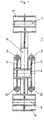
- Fig. 1 is a section through the brake device according to the invention shown.
- This consists essentially of the main body 1, the rollers 2, 2 'and the slot guide 6.
- the rollers 2, 2' are connected to each other via the shaft 4.
- This is positively or positively connected to the pair of rollers 2.
- the base body 1 has at its free ends fastening elements 11, 11 ', in which a fastening opening 5 is introduced. By means of the fastening openings 5, the base body 1 with the rollers 2, 2 'in the cabinet interior in relation to the blind pull can be attached.
- the arranged parallel to the roller axis fasteners 11, 11 'are designed so that their width is slightly larger than that of the shaft 4 connected to the rollers 2, 2'.
- the main body 1 is designed so that it can be mounted both left and
- the Fig. 2 shows a pair of roles. This consists of the two rollers 2, 2 ', wherein on one of the two rollers 2, 2', a shaft 4 is formed. After inserting the shaft 4 through the slot guide 6 in the base body 1, the second roller 2, 2 'are plugged. On the outer circumference of the rollers 2, 2 ', the circular running ring elements 3, 3' are introduced. By using a pair of rollers this can not be misjudged in the movement within the slot guide 6 of the base body 1. When using a single roller 2, 2 'in the base body 1, it can lead to jamming or stiffness.
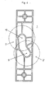
- the Fig. 3 shows the main body 1 in a side view.
- This center slot guide 6 is arranged approximately.
- the slot guide 6 is divided into two different guide slots 7 and 8.
- the flatter guide slot 7 extends at an angle of about 5 ° with respect to the longitudinal axis of the main body 1. Moving the rollers 2, 2 'on the shaft 4 in this guide slot 7 causes a slowing down of the blind train.
- the guide slot 8 is much steeper. The angle is approximately 30 ° with respect to the longitudinal axis of the base body 1. When moving the rollers 2, 2 'on the shaft 4 in this guide slot 8, the braking effect on the blind pull is canceled.
- the braking device according to the invention is used in so-called roll cabinets.
- the front side is closed by a blind pull.
- the blind pull When opening, the blind pulls up in a worm or on a roll. Since the shutter pulls open from above and moves out of the screw during unlocking due to its own weight, unrestrained implementations can lead to operator injuries or damage to the pull-pull / cabinet.
- the shaft 4 moves the rollers 2, 2 'in the guide slot 7 to the lower end position 10.
- the two ring elements 3, 3 'on the rollers 2, 2' which are designed in this embodiment as silicone rings, you need no additional brake shoe, which must be mounted very accurately on the inner side of the blind pull to achieve optimum braking effect ,
Landscapes
- Engineering & Computer Science (AREA)
- Structural Engineering (AREA)
- Architecture (AREA)
- Civil Engineering (AREA)
- Blinds (AREA)
- Braking Arrangements (AREA)
- Braking Systems And Boosters (AREA)
- Glass Compositions (AREA)
- Operating, Guiding And Securing Of Roll- Type Closing Members (AREA)
Description
- Die Erfindung betrifft eine Bremsvorrichtung für Jalousiezüge oder dergleichen translatorisch bewegbare und/oder aufrollbare Roll- oder Schiebelemente von insbesondere Möbeln, wobei die Jalousiezüge aus nebeneinander angeordneten parallelen und in Querrichtung der Jalousien verlaufenden Stäben, Leisten oder ähnlichen zusammengesetzt und diese an ihren Querkanten in in den einander gegenüberliegenden Seitenwänden ausgeführten Nuten oder ähnlichen Führungsschienen hin und her beweglich geführt sind.
- Schränke mit Jalousiezügen, auch als Rollschränke bezeichnet, finden heute vielfältig speziell in Büroeinrichtungen Verwendung. Rollschränke haben den Vorteil, dass sie hinsichtlich des Platzbedarfs sehr vorteilhaft sind. Sie nehmen den gleichen Platz in Anspruch unabhängig davon, ob sie geöffnet oder geschlossen sind. Rollschränke sind im allgemeinen so ausgeführt, dass an den vertikalen Schrankseiten Nuten ausgebildet sind, in denen sich die Jalousiezüge bewegen und zwar derart, dass sich die Jalousiezüge vorzugsweise auf- bzw. abwärts bewegen. Die Jalousiezüge werden üblicherweise aus Stäben, Leisten oder Ähnlichem gebildet und können rückseitig an einem einheitlichen Stoff oder einer ähnlichen Bahn befestigt sein.
- Jalousiezüge und die mit ihnen korrespondierenden Nuten müssen so ausgebildet sein, dass zum einen die Nuten so breit ausgeführt werden müssen, dass der Jalousiezug darin leicht und ohne großen Kraftaufwand läuft. Zum anderen darf der Jalousiezug in den Nuten nicht zu leicht laufen, da dieser sonst beispielsweise auf die Finger fallen kann und so Verletzungen verursachen kann.
- Jalousiezüge haben bei Rollschränken, in denen der Jalousiezug vertikal bewegt wird, d. h. auf- bzw. abwärts, den Nachteil, dass diese sich beim Öffnen oder Schließen ungebremst bewegen, wodurch ein gewisses Verletzungsrisiko beim Benutzer entstehen kann.
- Um diese Nachteile zu beseitigen, ist bereits vorgeschlagen worden, im hinteren Teil von Jalousiezug und Schrank ein Federsystem unterzubringen.
- In der
EP 1 076152 A1 wird ebenfalls eine gattungsgemäße Bremsvorrichtung beschrieben. Diese Bremsvorrichtung wird für eine Schrankrollladentür eingesetzt, deren seitliche Kanten jeweils in einem Kanal/Führungsschiene geführt sind. Die Bremsvorrichtung ist an beiden Seiten des der Schrankinnenwand an der Führungsschiene/dem Kanal geordnet. Die Bremselemente der Bremsvorrichtung sind jeweils auf einem Hebel exzentrisch angeordnet. Bei Bewegung der Schrankrollladentür nach unten wird die Bremsvorrichtung in Gang gesetzt. Bei dieser Bewegung drückt das Bremselement die seitliche Kante der Schrankrollladentür gegen den Kanal/Führungseinrichtung derart, dass sich die Reibungskraft zwischen beiden wesentlich erhöht und eine Verzögerung der Bewegung hervorruft. - Mit diesem Federsystem wird erreicht, dass der Jalousiezug leicht in der Nut läuft, ohne sich beim Loslassen von selbst zu bewegen. Der Nachteil dieser Lösung besteht darin, dass einerseits das Federsystem sehr kompliziertes aufgebaut und andererseits eine doppelte Rückwand erforderlich ist.
- Eine weitere Möglichkeit besteht darin, die Nuten relativ breit auszuführen, um die Beweglichkeit des Jalousiezuges zu gewährleisten, und in der Nut einen bremsenden Stoff (z.B. Polyurethan) zum Bremsen der Jalousiebewegung anzubringen.
Des weiteren wurde vorgeschlagen, an bestimmten Stäben des Jalousiezuges Reibungszapfen anzubringen, die in den Nuten laufen und die Jalousiebewegung bremsen.
In der Funktionsfähigkeit dieser Möglichkeiten traten jedoch Nachteile und Probleme auf. - Bremsvorrichtungen der eingangs beschrieben Art bestehen herkömmlicherweise aus an den Enden von Jalousiezügen befestigten Seilzügen, die ihrerseits mit einem eine Drehfeder und einen Arretierkörper aufweisenden Feststell- oder Bremskörper verbunden sind, der sich vorzugsweise im Schrankinneren im hinteren Bereich quer durch das Möbel erstreckt.
Diese sind bei Reparaturen nur sehr schwer zugänglich, so dass am Möbel selbst erhebliche Arbeiten auszuführen sind, um defekte Teile der Bremseinrichtung auszutauschen oder diese zu reparieren. - Weiterhin werden als Bremsvorrichtungen federbelastete Rollen, die auf die Innenseite des Jalousiezuges wirken, verwendet. Das durch eine Federkraft belastete und sich auf der Innenseite abstützende Element drückt die Außenfläche des Jalousiezuges gegen die Außenkante der Nut oder einer ähnlichen Führungsschiene, um so die der Bewegung des Jalousiezuges entgegen wirkende Reibungskraft zu erhöhen.
Diese Lösung hat den Nachteil, dass die Bremseinrichtung ständig im Eingriff steht, so dass das Öffnen oder Schließen nur gegen Überwindung der entgegenwirkenden Reibungskraft möglich ist. Eine Leichtgängigkeit ist somit nicht gegeben. - Eine Bremsvorrichtung, die auf den Jalousiezug wirkt, ist aus der
DE 195 31 071 C1 bekannt. - Die hier beschriebene Bremsvorrichtung besteht aus einem in einem Gehäuse angeordneten Bremskörper, wobei der Bremskörper als bewegliche, aus einer in Bremsrichtung arretierenden Bremsbetriebsstellung durch ein mit dem Jalousiezug koppelbaren Betätigungselement in eine Freigabestellung überführbare Bremsbacke ausgebildet ist. Durch die bewegliche Anordnung des Bremskörpers innerhalb des Gehäuses ist dieser in Folge des Eigengewichtes bei geöffnetem Jalousiezug automatisch in der Bremsstellung gelegen. Wird der Jalousiezug geöffnet, wird die Bremsbacke durch den Betätigungskörper, z.B. einen Streifen aus einem elastischen Material im Verlaufe der Öffnungsbewegung des Jalousiezuges automatisch in seine Freigabestellung überführt, so dass der Jalousiezug ohne irgendwelche Behinderungen durch den Bremskörper selbst in seine geöffnete Stellung gebracht werden kann.
- Derartige Bremseinrichtungen sind konstruktiv sehr aufwendig und dadurch bedingt auch teuer. Darüber hinaus kann es durch den an der Innenseite des Jalousiezuges reibenden Bremskörpers zu Zerstörungen der Jalousiezüge kommen.
- Der vorliegenden Erfindung liegt die Aufgabe zu Grunde, eine neue Bremsvorrichtung für Jalousiezüge zu schaffen, mit der die oben erläuterten mit dem bekannten Stand der Technik verbundenen Nachteile beseitigt werden können, und die mit einfachen baulichen Mitteln hergestellt werden kann und einen geringen Kostenaufwand verursacht.
- Erfindungsgemäß wird die Aufgabe dadurch gelöst, dass der Bremskörper der Bremsvorrichtung aus wenigstens einer orthogonal zum Jalousiezug angeordneten Rolle besteht, die an ihrem Umfang ein Ringelement aufweist, wobei die Rolle über eine Welle drehbeweglich gelagert und in einer im Grundkörper angeordneten Schlitzführung geführt ist, wobei die Rolle auf die Innenfläche des Jalousiezuges wirkt.
- Die Schlitzführung ist in zwei miteinander verbundene Führungskulissen aufgeteilt. Die Führungskulissen sind vorteilhafterweise winklig zueinander ausgeführt, wobei die eine Führungskulisse in einem geringeren Winkel zur Längsachse des Grundkörpers angeordnet ist als die andere Führungskulisse. Wesentlich an der Erfindung ist die Schlitzführung, in der die Rolle bewegbar ist.
- Über die Führungskulisse mit dem kleineren Winkel wird die Rolle durch den Jalousiezug in die untere Endlage verfahren. Dadurch verringert sich der Abstand des Rollenpaares zum Jalousiezug.
Der Jalousiezug wird dadurch mit seiner Außenseite gegen die Innenkante der Nut bzw. Führungskulisse gedrückt und somit die Reibungskraft erhöht. Infolge dessen wird der Jalousiezug abgebremst. Bei der entgegengesetzten Bewegung des Jalousiezuges wird die Rolle in die zweite Führungskulisse verfahren. Diese ist wesentlich steiler ausgeführt, so dass die Bremswirkung auf den Jalousiezug aufgehoben wird. Dadurch, dass die Rolle nunmehr in die obere Endlage verfahren wird, ist auch der Druck auf den Jalousiezug aufgehoben. Der Jalousiezug ist wieder leicht bewegbar.
Durch die vorteilhafte Verwendung eines Rollenpaares können Verkantungen bei ihrem Verfahren in die jeweilige Endlage der Schlitzführung vermieden werden.
Die einzelnen Rollen weisen eine Ringnut zur Aufnahme von Ringelementen auf. Die Ringnut kann voll umfänglich oder in Segmenten ausgeformt sein. Mindestens ein Grundkörper mit dem Bremskörper ist im nicht sichtbaren Bereich zwischen einer das Innere der Möbel freigebenden bzw. verschließenden Position des Jalousiezuges angeordnet. - Die Vorteile der erfindungsgemäßen Bremsvorrichtung sind zum einen in einem geräuscharmen Bremsvorgang, da sich die Rolle mitdreht, und zum anderen in einem geringen Verschleißverhalten, da die Ringelemente, welche beispielsweise aus Silikon bestehen, nicht bleibend verformt werden und ein gutes Rückstellverhalten aufweisen, zu sehen.
Ein weiterer Vorteil ist, dass die Bremsvorrichtung so ausgebildet ist, dass sie sowohl rechts oder links als auch horizontal oder vertikal, insbesondere bei Möbeln, eingesetzt werden kann. - Anhand eines Ausführungsbeispiels soll die Erfindung näher erläutert werden. Es zeigen
- Figur 1 -
- Schnitt durch die erfindungsgemäße Bremsvorrichtung
- Figur 2 -
- Rollenpaar
- Figur 3 -
- Grundkörper
- Figur 4 -
- Darstellung der Endlagenpunkte für das Rollenpaar
- In der
Fig. 1 ist ein Schnitt durch die erfindungsgemäße Bremsvorrichtung dargestellt.
Diese besteht im Wesentlichen aus dem Grundkörper 1, den Rollen 2, 2' und der Schlitzführung 6. Die Rollen 2, 2', sind über die Welle 4 miteinander verbunden. Die Rollen 2, 2' sind an ihrem äußeren Umfang so ausgebildet, dass sie zwei Ringnuten 12, 12' aufweisen, die Ringelemente 3, 3' aufnehmen können, was in diesem Ausführungsbeispiel ein Silikonring ist. Dieser ist kraftschlüssig bzw. formschlüssig mit dem Rollenpaar 2 verbunden. Der Grundkörper 1 weist an seinen freien Enden Befestigungselemente 11, 11' auf, in denen eine Befestigungsöffnung 5 eingebracht ist. Mittels der Befestigungsöffnungen 5 kann der Grundkörper 1 mit den Rollen 2, 2' im Schrankinneren in Bezug zum Jalousiezug befestigt werden. Die parallel zur Rollenachse angeordneten Befestigungselemente 11, 11' sind so ausgeführt, dass ihre Breite geringfügig größer ist, als die der über die Welle 4 verbundenen Rollen 2, 2'. Der Grundkörper 1 ist so ausgelegt, dass dieser sowohl links als auch rechts im Schrankinneren angebracht werden kann. - Die
Fig. 2 zeigt ein Rollenpaar. Dieses besteht aus den beiden Rollen 2, 2', wobei an einer der beiden Rollen 2, 2' eine Welle 4 angeformt ist. Nach dem Durchstecken der Welle 4 durch die Schlitzführung 6 im Grundkörper 1 kann die zweite Rolle 2, 2' aufgesteckt werden. Am äußeren Umfang der Rollen 2, 2' sind die kreisförmig ausgeführten Ringelemente 3, 3' eingebracht. Durch die Verwendung eines Rollenpaares kann dieses bei der Bewegung innerhalb der Schlitzführung 6 des Grundkörpers 1 nicht verkannten. Bei Verwendung einer einzelnen Rolle 2, 2' im Grundkörper 1 kann es zum Verklemmen bzw. zur Schwergängigkeit kommen. - Die
Fig. 3 zeigt den Grundkörper 1 in einer Seitenansicht. In diesem ist in etwa mittig die Schlitzführung 6 angeordnet. Die Schlitzführung 6 ist in zwei unterschiedliche Führungskulissen 7 und 8 aufgeteilt. Die flachere Führungskulisse 7 verläuft in einem Winkel von etwa 5° in Bezug zur Längsachse des Grundkörpers 1. Das Bewegen der Rollen 2, 2' über die Welle 4 in dieser Führungskulisse 7 bewirkt ein Abbremsen des Jalousiezuges. Die Führungskulisse 8 verläuft wesentlich steiler. Der Winkel beträgt in etwa 30° in Bezug auf die Längsachse des Grundkörpers 1. Beim Bewegen der Rollen 2, 2' über die Welle 4 in dieser Führungskulisse 8 wird die Bremswirkung auf den Jalousiezug aufgehoben. - In der
Fig. 4 sind die Endlagen 9 und 10 der Rollen 2, 2' im Grundkörper 1 dargestellt. Befinden sich die Rollen 2, 2' - hier strichpunktiert dargestellt - in der oberen Endlage 9, ist die Bremswirkung vollständig aufgehoben. Der Jalousiezug lässt sich frei innerhalb der Führungsnuten bewegen. Befinden sich die Rollen 2, 2' in der unteren Endlage 10, wird der größtmögliche Druck auf den Jalousiezug erreicht. Dieser wird über in der Ringnut 12, 12' der Rollen 2, 2' befindlichen Ringelemente 3, 3' abgebremst und mit seiner Außenseite gegen die Außenkante der Führungsnut gedrückt und somit die Reibungskraft erhöht. Der Jalousiezug wird abgebremst. - Die erfindungsgemäße Bremsvorrichtung wird in sogenannten Rollschränken verwendet. Die Frontseite wird durch einen Jalousiezug verschlossen. Beim Öffnen wird der Jalousiezug in einer Schnecke bzw. auf einer Rolle aufgewickelt.
Da der Jalousiezug von oben öffnet und beim Aufsperren durch das Eigengewicht aus der Schnecke fährt, kann dies bei ungebremsten Ausführungen zu Verletzungen des Bedieners bzw. zu Beschädigungen am Jalousiezug/Schrank führen.
Durch die beiden nebeneinanderliegenden Rollen 2, 2' wird der Jalousiezug abgebremst. Dazu verfährt die Welle 4 der Rollen 2, 2' in die Führungskulisse 7 bis in die untere Endlage 10. Beim Hochziehen des Jalousiezuges klinken sich die über die Welle 4 verbundenen Rollen 2, 2' aus und der Jalousiezug kann ohne spürbares Hindernis wieder nach oben gezogen werden.
Durch die beiden Ringelemente 3, 3' auf den Rollen 2, 2', die in diesem Ausführungsbeispiel als Silikonringe ausgeführt sind, benötigt man keinen zusätzlichen Bremsschuh, der sehr genau auf der innenliegenden Seite des Jalousiezuges montiert werden muss, um eine optimale Bremswirkung zu erzielen. -
- 1 -
- Grundkörper
- 2, 2' -
- Rolle
- 3, 3' -
- Ringelement
- 4 -
- Welle
- 5 -
- Befestigungsbohrung
- 6 -
- Schlitzführung
- 7 -
- Führungskulisse
- 8 -
- Führungskulisse
- 9 -
- obere Endlage
- 10 -
- untere Endlage
- 11, 11' -
- Befestigungselement
- 12, 12' -
- Ringnut
Claims (6)
- Bremsvorrichtung für Jalousiezüge oder dergleichen mit translatorisch bewegbaren und/oder aufrollbaren Roll- oder Schiebelemente von, insbesondere, Möbeln, wobei die Jalousiezüge aus nebeneinander angeordneten parallelen und in Querrichtung der Jalousien verlaufenden Stäben, Leisten oder Ähnlichem zusammengesetzt und diese an ihren Querkanten in in den einander gegenüberliegenden Seitenwänden ausgeführten Nuten oder ähnlichen Führungsschienen hin und her beweglich geführt sind und einem am Jalousiezug anordbaren Bremskörper,
dadurch gekennzeichnet,
dass der Bremskörper aus wenigstens einer orthogonal zum Jalousiezug anordbaren Rolle (2, 2') besteht, die auf ihrem äußeren Umfang ein Ringelement (3,3') aufweist, wobei die Rolle (2, 2') über eine Welle (4) drehbeweglich gelagert ist und in einer in einem Grundkörper (1) angeordneten Schlitzführung (6) geführt ist die auf die Innenfläche des Jalousiezüge wirken kann, wobei die Schlitzführung (6) zwei miteinander verbundene Führungskulissen (7, 8) aufweist und wobei die eine Führungskulisse (7) in einem geringeren Winkel zur Längsachse des Grund- körpers (1) geneigt ist als die andere Führungskulisse (8). - Bremsvorrichtung für Jalousiezüge nach Anspruch 1, dadurch gekennzeichnet, dass die Führungskulissen (7, 8) winklig zueinander angeordnet sind.
- Bremsvorrichtung für Jalousiezüge nach Anspruch 1 bis 2, dadurch gekennzeichnet dass die Rolle (2, 2') eine Ringnut (12, 12,') aufweist.
- Bremsvorrichtung für Jalousiezüge nach Anspruch 1 bis 3, dadurch gekennzeichnet, dass die Ringnut (12, 12') der Rolle (2, 2') voll oder in Segmenten ausgebildet ist
- Bremsvorrichtung für Jalousiezüge nach Anspruch 1 bis 4, dadurch gekennzeichnet, dass mindestens ein Bremskörper im nicht sichtbaren Bereich zwischen einer das Innere der Möbel freigebenden bzw. verschließenden Position des Jalousiezuges anordbar ist.
- Möbel, insbesondere Büromöbel mit einem aus mehreren Platten bestehenden Möbelkörper und einem zueinander gegenüberliegenden Seitenwänden ausgeführten Nuten oder Führungsschienen translatorisch bewegbaren Jalousiezug mit einer Bremsvorrichtung gemäß einem der Ansprüche 1 bis 5.
Applications Claiming Priority (2)
| Application Number | Priority Date | Filing Date | Title |
|---|---|---|---|
| DE20116880U DE20116880U1 (de) | 2001-10-13 | 2001-10-13 | Bremsvorrichtung für Jalousiezüge |
| DE20116880U | 2001-10-13 |
Publications (3)
| Publication Number | Publication Date |
|---|---|
| EP1306514A2 EP1306514A2 (de) | 2003-05-02 |
| EP1306514A3 EP1306514A3 (de) | 2003-12-17 |
| EP1306514B1 true EP1306514B1 (de) | 2010-09-15 |
Family
ID=7962861
Family Applications (1)
| Application Number | Title | Priority Date | Filing Date |
|---|---|---|---|
| EP02021933A Expired - Lifetime EP1306514B1 (de) | 2001-10-13 | 2002-09-28 | Bremsvorrichtung für Jalousiezüge |
Country Status (3)
| Country | Link |
|---|---|
| EP (1) | EP1306514B1 (de) |
| AT (1) | ATE481551T1 (de) |
| DE (2) | DE20116880U1 (de) |
Family Cites Families (7)
| Publication number | Priority date | Publication date | Assignee | Title |
|---|---|---|---|---|
| CH63141A (de) | 1912-12-30 | 1914-01-02 | Walser & Cie H | Klammer zum Halten von flachen Gegenständen |
| DE2610604A1 (de) | 1976-03-13 | 1977-09-15 | Erich Ing Grad Steinborn | Schutzvorrichtung, insbesondere diebstahlsicherung, an rolladen und dergleichen |
| DE3109327A1 (de) | 1981-03-12 | 1982-11-04 | Werner 5400 Koblenz Vogt | Rolladensicherung mit kaeltestopp und sicherheitsverschluss |
| DE3611022A1 (de) | 1986-03-29 | 1987-12-23 | Thomas Grahn | Ausruecker fuer rollos |
| DE19531071C1 (de) | 1995-08-23 | 1996-11-14 | Fennel Gmbh | Bremsvorrichtung für Jalousiezüge |
| FI963706A7 (fi) * | 1996-09-19 | 1998-03-20 | Martela Ag | Rulo-oven jarrulaite |
| SE518540C2 (sv) * | 1999-08-09 | 2002-10-22 | Kinnarps Ab | Bromsanordning för jalusidörr |
-
2001
- 2001-10-13 DE DE20116880U patent/DE20116880U1/de not_active Expired - Lifetime
-
2002
- 2002-09-28 EP EP02021933A patent/EP1306514B1/de not_active Expired - Lifetime
- 2002-09-28 DE DE50214656T patent/DE50214656D1/de not_active Expired - Lifetime
- 2002-09-28 AT AT02021933T patent/ATE481551T1/de not_active IP Right Cessation
Also Published As
| Publication number | Publication date |
|---|---|
| ATE481551T1 (de) | 2010-10-15 |
| EP1306514A3 (de) | 2003-12-17 |
| DE50214656D1 (de) | 2010-10-28 |
| EP1306514A2 (de) | 2003-05-02 |
| DE20116880U1 (de) | 2001-12-13 |
Similar Documents
| Publication | Publication Date | Title |
|---|---|---|
| DE112013007355B4 (de) | Scharnier für eine Falttür | |
| EP0519241B1 (de) | Zugvorrichtung vorzugsweise zum Ein- und Ausziehen eines Tuches für eine Store, sowie dazugehörige Store | |
| DE2227931A1 (de) | Gleitvorrichtung | |
| EP2992156B1 (de) | Führungsanordnung einer schiebetür, schiebetür und möbel | |
| DE102011011113B4 (de) | Rahmensystem eines Partikelschutzgitters | |
| EP2730734A2 (de) | Bidirektionale Einzugsvorrichtung für eine mittlere Schiebetür | |
| DE202014011057U1 (de) | Vitrine zur Zurschaustellung von Gegenständen | |
| DE202009014785U1 (de) | Schiebetür | |
| AT512896B1 (de) | Schiebefenster, Schiebetür od. dgl. und Dichtvorrichtung hiefür | |
| EP1820928A2 (de) | Sektionaltor | |
| EP3763911B1 (de) | Führungsschienenvorrichtung für ein rolltor oder ein rollgitter | |
| DE2856171A1 (de) | Faltbare tuer oder wand | |
| EP2859170A1 (de) | Rollladenschrank | |
| DE68903285T2 (de) | Verschluss mit faltfluegeln. | |
| WO2007019926A1 (de) | Schrankmöbel | |
| DE2826002C2 (de) | ||
| DE102016124955B4 (de) | Verriegelungsvorrichtung eines Verriegelungssystems, Verriegelungssystem sowie Schiebewandanlage | |
| DE4323993A1 (de) | Falt- oder raffbarer Vorhang | |
| EP3085281B1 (de) | Gleitelement zum verschiebbaren lagern eines vorhanges oder einer plane | |
| DE29917503U1 (de) | Vorrichtung | |
| DE29701260U1 (de) | Führungseinrichtung für eine Schiebetür | |
| DE20116880U1 (de) | Bremsvorrichtung für Jalousiezüge | |
| EP1394350B1 (de) | Möbel mit einer Bremsvorrichtung für Jalousiezüge | |
| DE20121274U1 (de) | Schiebetür zum Verschließen einer Wandöffnung | |
| AT411088B (de) | Stab für verschiebbare, öffnungen zugeordnete vorrichtungen, wie rollläden |
Legal Events
| Date | Code | Title | Description |
|---|---|---|---|
| PUAI | Public reference made under article 153(3) epc to a published international application that has entered the european phase |
Free format text: ORIGINAL CODE: 0009012 |
|
| AK | Designated contracting states |
Designated state(s): AT BE BG CH CY CZ DE DK EE ES FI FR GB GR IE IT LI LU MC NL PT SE SK TR |
|
| AX | Request for extension of the european patent |
Extension state: AL LT LV MK RO SI |
|
| PUAL | Search report despatched |
Free format text: ORIGINAL CODE: 0009013 |
|
| AK | Designated contracting states |
Kind code of ref document: A3 Designated state(s): AT BE BG CH CY CZ DE DK EE ES FI FR GB GR IE IT LI LU MC NL PT SE SK TR |
|
| AX | Request for extension of the european patent |
Extension state: AL LT LV MK RO SI |
|
| 17P | Request for examination filed |
Effective date: 20040129 |
|
| AKX | Designation fees paid |
Designated state(s): AT BE BG CH CY CZ DE DK EE ES FI FR GB GR IE IT LI LU MC NL PT SE SK TR |
|
| 17Q | First examination report despatched |
Effective date: 20050506 |
|
| GRAP | Despatch of communication of intention to grant a patent |
Free format text: ORIGINAL CODE: EPIDOSNIGR1 |
|
| RIC1 | Information provided on ipc code assigned before grant |
Ipc: E06B 9/11 20060101AFI20100325BHEP Ipc: E06B 9/80 20060101ALI20100325BHEP |
|
| GRAS | Grant fee paid |
Free format text: ORIGINAL CODE: EPIDOSNIGR3 |
|
| GRAA | (expected) grant |
Free format text: ORIGINAL CODE: 0009210 |
|
| AK | Designated contracting states |
Kind code of ref document: B1 Designated state(s): AT BE BG CH CY CZ DE DK EE ES FI FR GB GR IE IT LI LU MC NL PT SE SK TR |
|
| REG | Reference to a national code |
Ref country code: GB Ref legal event code: FG4D Free format text: NOT ENGLISH Ref country code: CH Ref legal event code: EP |
|
| REG | Reference to a national code |
Ref country code: IE Ref legal event code: FG4D Free format text: LANGUAGE OF EP DOCUMENT: GERMAN |
|
| REF | Corresponds to: |
Ref document number: 50214656 Country of ref document: DE Date of ref document: 20101028 Kind code of ref document: P |
|
| REG | Reference to a national code |
Ref country code: NL Ref legal event code: VDEP Effective date: 20100915 |
|
| PG25 | Lapsed in a contracting state [announced via postgrant information from national office to epo] |
Ref country code: FI Free format text: LAPSE BECAUSE OF FAILURE TO SUBMIT A TRANSLATION OF THE DESCRIPTION OR TO PAY THE FEE WITHIN THE PRESCRIBED TIME-LIMIT Effective date: 20100915 |
|
| PG25 | Lapsed in a contracting state [announced via postgrant information from national office to epo] |
Ref country code: CY Free format text: LAPSE BECAUSE OF FAILURE TO SUBMIT A TRANSLATION OF THE DESCRIPTION OR TO PAY THE FEE WITHIN THE PRESCRIBED TIME-LIMIT Effective date: 20100915 |
|
| BERE | Be: lapsed |
Owner name: REHAU A.G. + CO Effective date: 20100930 |
|
| PG25 | Lapsed in a contracting state [announced via postgrant information from national office to epo] |
Ref country code: GR Free format text: LAPSE BECAUSE OF FAILURE TO SUBMIT A TRANSLATION OF THE DESCRIPTION OR TO PAY THE FEE WITHIN THE PRESCRIBED TIME-LIMIT Effective date: 20101216 Ref country code: SE Free format text: LAPSE BECAUSE OF FAILURE TO SUBMIT A TRANSLATION OF THE DESCRIPTION OR TO PAY THE FEE WITHIN THE PRESCRIBED TIME-LIMIT Effective date: 20100915 |
|
| REG | Reference to a national code |
Ref country code: IE Ref legal event code: FD4D |
|
| PG25 | Lapsed in a contracting state [announced via postgrant information from national office to epo] |
Ref country code: IE Free format text: LAPSE BECAUSE OF FAILURE TO SUBMIT A TRANSLATION OF THE DESCRIPTION OR TO PAY THE FEE WITHIN THE PRESCRIBED TIME-LIMIT Effective date: 20100915 Ref country code: MC Free format text: LAPSE BECAUSE OF NON-PAYMENT OF DUE FEES Effective date: 20100930 |
|
| REG | Reference to a national code |
Ref country code: CH Ref legal event code: PL |
|
| PG25 | Lapsed in a contracting state [announced via postgrant information from national office to epo] |
Ref country code: EE Free format text: LAPSE BECAUSE OF FAILURE TO SUBMIT A TRANSLATION OF THE DESCRIPTION OR TO PAY THE FEE WITHIN THE PRESCRIBED TIME-LIMIT Effective date: 20100915 Ref country code: NL Free format text: LAPSE BECAUSE OF FAILURE TO SUBMIT A TRANSLATION OF THE DESCRIPTION OR TO PAY THE FEE WITHIN THE PRESCRIBED TIME-LIMIT Effective date: 20100915 Ref country code: SK Free format text: LAPSE BECAUSE OF FAILURE TO SUBMIT A TRANSLATION OF THE DESCRIPTION OR TO PAY THE FEE WITHIN THE PRESCRIBED TIME-LIMIT Effective date: 20100915 Ref country code: PT Free format text: LAPSE BECAUSE OF FAILURE TO SUBMIT A TRANSLATION OF THE DESCRIPTION OR TO PAY THE FEE WITHIN THE PRESCRIBED TIME-LIMIT Effective date: 20110117 Ref country code: CZ Free format text: LAPSE BECAUSE OF FAILURE TO SUBMIT A TRANSLATION OF THE DESCRIPTION OR TO PAY THE FEE WITHIN THE PRESCRIBED TIME-LIMIT Effective date: 20100915 Ref country code: IT Free format text: LAPSE BECAUSE OF FAILURE TO SUBMIT A TRANSLATION OF THE DESCRIPTION OR TO PAY THE FEE WITHIN THE PRESCRIBED TIME-LIMIT Effective date: 20100915 |
|
| PG25 | Lapsed in a contracting state [announced via postgrant information from national office to epo] |
Ref country code: ES Free format text: LAPSE BECAUSE OF FAILURE TO SUBMIT A TRANSLATION OF THE DESCRIPTION OR TO PAY THE FEE WITHIN THE PRESCRIBED TIME-LIMIT Effective date: 20101226 |
|
| PLBE | No opposition filed within time limit |
Free format text: ORIGINAL CODE: 0009261 |
|
| STAA | Information on the status of an ep patent application or granted ep patent |
Free format text: STATUS: NO OPPOSITION FILED WITHIN TIME LIMIT |
|
| PG25 | Lapsed in a contracting state [announced via postgrant information from national office to epo] |
Ref country code: LI Free format text: LAPSE BECAUSE OF NON-PAYMENT OF DUE FEES Effective date: 20100930 Ref country code: CH Free format text: LAPSE BECAUSE OF NON-PAYMENT OF DUE FEES Effective date: 20100930 Ref country code: BE Free format text: LAPSE BECAUSE OF NON-PAYMENT OF DUE FEES Effective date: 20100930 |
|
| 26N | No opposition filed |
Effective date: 20110616 |
|
| GBPC | Gb: european patent ceased through non-payment of renewal fee |
Effective date: 20101215 |
|
| PG25 | Lapsed in a contracting state [announced via postgrant information from national office to epo] |
Ref country code: DK Free format text: LAPSE BECAUSE OF FAILURE TO SUBMIT A TRANSLATION OF THE DESCRIPTION OR TO PAY THE FEE WITHIN THE PRESCRIBED TIME-LIMIT Effective date: 20100915 |
|
| REG | Reference to a national code |
Ref country code: DE Ref legal event code: R097 Ref document number: 50214656 Country of ref document: DE Effective date: 20110616 |
|
| PG25 | Lapsed in a contracting state [announced via postgrant information from national office to epo] |
Ref country code: AT Free format text: LAPSE BECAUSE OF NON-PAYMENT OF DUE FEES Effective date: 20100928 Ref country code: GB Free format text: LAPSE BECAUSE OF NON-PAYMENT OF DUE FEES Effective date: 20101215 |
|
| PGFP | Annual fee paid to national office [announced via postgrant information from national office to epo] |
Ref country code: DE Payment date: 20110930 Year of fee payment: 10 |
|
| REG | Reference to a national code |
Ref country code: FR Ref legal event code: ST Effective date: 20111125 |
|
| PG25 | Lapsed in a contracting state [announced via postgrant information from national office to epo] |
Ref country code: FR Free format text: LAPSE BECAUSE OF NON-PAYMENT OF DUE FEES Effective date: 20101115 |
|
| PG25 | Lapsed in a contracting state [announced via postgrant information from national office to epo] |
Ref country code: LU Free format text: LAPSE BECAUSE OF NON-PAYMENT OF DUE FEES Effective date: 20100928 Ref country code: BG Free format text: LAPSE BECAUSE OF FAILURE TO SUBMIT A TRANSLATION OF THE DESCRIPTION OR TO PAY THE FEE WITHIN THE PRESCRIBED TIME-LIMIT Effective date: 20100915 |
|
| PG25 | Lapsed in a contracting state [announced via postgrant information from national office to epo] |
Ref country code: TR Free format text: LAPSE BECAUSE OF FAILURE TO SUBMIT A TRANSLATION OF THE DESCRIPTION OR TO PAY THE FEE WITHIN THE PRESCRIBED TIME-LIMIT Effective date: 20100915 |
|
| PG25 | Lapsed in a contracting state [announced via postgrant information from national office to epo] |
Ref country code: DE Free format text: LAPSE BECAUSE OF NON-PAYMENT OF DUE FEES Effective date: 20130403 |
|
| REG | Reference to a national code |
Ref country code: DE Ref legal event code: R119 Ref document number: 50214656 Country of ref document: DE Effective date: 20130403 |
|
| PG25 | Lapsed in a contracting state [announced via postgrant information from national office to epo] |
Ref country code: BG Free format text: LAPSE BECAUSE OF FAILURE TO SUBMIT A TRANSLATION OF THE DESCRIPTION OR TO PAY THE FEE WITHIN THE PRESCRIBED TIME-LIMIT Effective date: 20101215 |