EP1306529B1 - Appareil de contrôle d'ouverture variable de soupapes pour moteur à combustion interne et méthode correspondante - Google Patents
Appareil de contrôle d'ouverture variable de soupapes pour moteur à combustion interne et méthode correspondante Download PDFInfo
- Publication number
- EP1306529B1 EP1306529B1 EP02024043A EP02024043A EP1306529B1 EP 1306529 B1 EP1306529 B1 EP 1306529B1 EP 02024043 A EP02024043 A EP 02024043A EP 02024043 A EP02024043 A EP 02024043A EP 1306529 B1 EP1306529 B1 EP 1306529B1
- Authority
- EP
- European Patent Office
- Prior art keywords
- valve
- variable valve
- exhaust
- lift amount
- internal combustion
- Prior art date
- Legal status (The legal status is an assumption and is not a legal conclusion. Google has not performed a legal analysis and makes no representation as to the accuracy of the status listed.)
- Expired - Lifetime
Links
- 238000002485 combustion reaction Methods 0.000 title claims description 32
- 238000000034 method Methods 0.000 title claims description 12
- 230000007246 mechanism Effects 0.000 claims description 104
- 230000005540 biological transmission Effects 0.000 claims description 5
- 238000001514 detection method Methods 0.000 claims description 2
- 239000003921 oil Substances 0.000 description 20
- 238000010586 diagram Methods 0.000 description 11
- 239000012530 fluid Substances 0.000 description 4
- 238000003780 insertion Methods 0.000 description 4
- 230000037431 insertion Effects 0.000 description 4
- 230000015556 catabolic process Effects 0.000 description 3
- 238000006731 degradation reaction Methods 0.000 description 3
- 239000000446 fuel Substances 0.000 description 3
- 238000002347 injection Methods 0.000 description 3
- 239000007924 injection Substances 0.000 description 3
- 238000005192 partition Methods 0.000 description 3
- 239000003054 catalyst Substances 0.000 description 2
- 238000012937 correction Methods 0.000 description 2
- 230000003111 delayed effect Effects 0.000 description 2
- 238000007599 discharging Methods 0.000 description 2
- 230000002093 peripheral effect Effects 0.000 description 2
- 238000011144 upstream manufacturing Methods 0.000 description 2
- 238000013459 approach Methods 0.000 description 1
- 238000010276 construction Methods 0.000 description 1
- 239000000498 cooling water Substances 0.000 description 1
- 230000003247 decreasing effect Effects 0.000 description 1
- 230000009977 dual effect Effects 0.000 description 1
- 238000012986 modification Methods 0.000 description 1
- 230000004048 modification Effects 0.000 description 1
- 238000005086 pumping Methods 0.000 description 1
- 239000010729 system oil Substances 0.000 description 1
- 238000012546 transfer Methods 0.000 description 1
- XLYOFNOQVPJJNP-UHFFFAOYSA-N water Substances O XLYOFNOQVPJJNP-UHFFFAOYSA-N 0.000 description 1
Images


Classifications
-
- F—MECHANICAL ENGINEERING; LIGHTING; HEATING; WEAPONS; BLASTING
- F02—COMBUSTION ENGINES; HOT-GAS OR COMBUSTION-PRODUCT ENGINE PLANTS
- F02D—CONTROLLING COMBUSTION ENGINES
- F02D13/00—Controlling the engine output power by varying inlet or exhaust valve operating characteristics, e.g. timing
- F02D13/02—Controlling the engine output power by varying inlet or exhaust valve operating characteristics, e.g. timing during engine operation
- F02D13/0223—Variable control of the intake valves only
- F02D13/0226—Variable control of the intake valves only changing valve lift or valve lift and timing
- F02D13/023—Variable control of the intake valves only changing valve lift or valve lift and timing the change of valve timing is caused by the change in valve lift, i.e. both valve lift and timing are functionally related
-
- F—MECHANICAL ENGINEERING; LIGHTING; HEATING; WEAPONS; BLASTING
- F01—MACHINES OR ENGINES IN GENERAL; ENGINE PLANTS IN GENERAL; STEAM ENGINES
- F01L—CYCLICALLY OPERATING VALVES FOR MACHINES OR ENGINES
- F01L1/00—Valve-gear or valve arrangements, e.g. lift-valve gear
- F01L1/02—Valve drive
- F01L1/022—Chain drive
-
- F—MECHANICAL ENGINEERING; LIGHTING; HEATING; WEAPONS; BLASTING
- F01—MACHINES OR ENGINES IN GENERAL; ENGINE PLANTS IN GENERAL; STEAM ENGINES
- F01L—CYCLICALLY OPERATING VALVES FOR MACHINES OR ENGINES
- F01L1/00—Valve-gear or valve arrangements, e.g. lift-valve gear
- F01L1/34—Valve-gear or valve arrangements, e.g. lift-valve gear characterised by the provision of means for changing the timing of the valves without changing the duration of opening and without affecting the magnitude of the valve lift
- F01L1/344—Valve-gear or valve arrangements, e.g. lift-valve gear characterised by the provision of means for changing the timing of the valves without changing the duration of opening and without affecting the magnitude of the valve lift changing the angular relationship between crankshaft and camshaft, e.g. using helicoidal gear
- F01L1/3442—Valve-gear or valve arrangements, e.g. lift-valve gear characterised by the provision of means for changing the timing of the valves without changing the duration of opening and without affecting the magnitude of the valve lift changing the angular relationship between crankshaft and camshaft, e.g. using helicoidal gear using hydraulic chambers with variable volume to transmit the rotating force
-
- F—MECHANICAL ENGINEERING; LIGHTING; HEATING; WEAPONS; BLASTING
- F01—MACHINES OR ENGINES IN GENERAL; ENGINE PLANTS IN GENERAL; STEAM ENGINES
- F01L—CYCLICALLY OPERATING VALVES FOR MACHINES OR ENGINES
- F01L13/00—Modifications of valve-gear to facilitate reversing, braking, starting, changing compression ratio, or other specific operations
- F01L13/0015—Modifications of valve-gear to facilitate reversing, braking, starting, changing compression ratio, or other specific operations for optimising engine performances by modifying valve lift according to various working parameters, e.g. rotational speed, load, torque
- F01L13/0021—Modifications of valve-gear to facilitate reversing, braking, starting, changing compression ratio, or other specific operations for optimising engine performances by modifying valve lift according to various working parameters, e.g. rotational speed, load, torque by modification of rocker arm ratio
- F01L13/0026—Modifications of valve-gear to facilitate reversing, braking, starting, changing compression ratio, or other specific operations for optimising engine performances by modifying valve lift according to various working parameters, e.g. rotational speed, load, torque by modification of rocker arm ratio by means of an eccentric
-
- F—MECHANICAL ENGINEERING; LIGHTING; HEATING; WEAPONS; BLASTING
- F02—COMBUSTION ENGINES; HOT-GAS OR COMBUSTION-PRODUCT ENGINE PLANTS
- F02D—CONTROLLING COMBUSTION ENGINES
- F02D13/00—Controlling the engine output power by varying inlet or exhaust valve operating characteristics, e.g. timing
- F02D13/02—Controlling the engine output power by varying inlet or exhaust valve operating characteristics, e.g. timing during engine operation
- F02D13/0242—Variable control of the exhaust valves only
- F02D13/0246—Variable control of the exhaust valves only changing valve lift or valve lift and timing
-
- F—MECHANICAL ENGINEERING; LIGHTING; HEATING; WEAPONS; BLASTING
- F01—MACHINES OR ENGINES IN GENERAL; ENGINE PLANTS IN GENERAL; STEAM ENGINES
- F01L—CYCLICALLY OPERATING VALVES FOR MACHINES OR ENGINES
- F01L1/00—Valve-gear or valve arrangements, e.g. lift-valve gear
- F01L1/02—Valve drive
- F01L1/024—Belt drive
-
- F—MECHANICAL ENGINEERING; LIGHTING; HEATING; WEAPONS; BLASTING
- F01—MACHINES OR ENGINES IN GENERAL; ENGINE PLANTS IN GENERAL; STEAM ENGINES
- F01L—CYCLICALLY OPERATING VALVES FOR MACHINES OR ENGINES
- F01L1/00—Valve-gear or valve arrangements, e.g. lift-valve gear
- F01L1/02—Valve drive
- F01L1/04—Valve drive by means of cams, camshafts, cam discs, eccentrics or the like
- F01L1/047—Camshafts
- F01L1/053—Camshafts overhead type
- F01L2001/0537—Double overhead camshafts [DOHC]
-
- F—MECHANICAL ENGINEERING; LIGHTING; HEATING; WEAPONS; BLASTING
- F01—MACHINES OR ENGINES IN GENERAL; ENGINE PLANTS IN GENERAL; STEAM ENGINES
- F01L—CYCLICALLY OPERATING VALVES FOR MACHINES OR ENGINES
- F01L1/00—Valve-gear or valve arrangements, e.g. lift-valve gear
- F01L1/34—Valve-gear or valve arrangements, e.g. lift-valve gear characterised by the provision of means for changing the timing of the valves without changing the duration of opening and without affecting the magnitude of the valve lift
- F01L1/344—Valve-gear or valve arrangements, e.g. lift-valve gear characterised by the provision of means for changing the timing of the valves without changing the duration of opening and without affecting the magnitude of the valve lift changing the angular relationship between crankshaft and camshaft, e.g. using helicoidal gear
- F01L1/3442—Valve-gear or valve arrangements, e.g. lift-valve gear characterised by the provision of means for changing the timing of the valves without changing the duration of opening and without affecting the magnitude of the valve lift changing the angular relationship between crankshaft and camshaft, e.g. using helicoidal gear using hydraulic chambers with variable volume to transmit the rotating force
- F01L2001/3445—Details relating to the hydraulic means for changing the angular relationship
- F01L2001/34453—Locking means between driving and driven members
- F01L2001/34469—Lock movement parallel to camshaft axis
-
- F—MECHANICAL ENGINEERING; LIGHTING; HEATING; WEAPONS; BLASTING
- F01—MACHINES OR ENGINES IN GENERAL; ENGINE PLANTS IN GENERAL; STEAM ENGINES
- F01L—CYCLICALLY OPERATING VALVES FOR MACHINES OR ENGINES
- F01L13/00—Modifications of valve-gear to facilitate reversing, braking, starting, changing compression ratio, or other specific operations
- F01L13/0015—Modifications of valve-gear to facilitate reversing, braking, starting, changing compression ratio, or other specific operations for optimising engine performances by modifying valve lift according to various working parameters, e.g. rotational speed, load, torque
- F01L13/0063—Modifications of valve-gear to facilitate reversing, braking, starting, changing compression ratio, or other specific operations for optimising engine performances by modifying valve lift according to various working parameters, e.g. rotational speed, load, torque by modification of cam contact point by displacing an intermediate lever or wedge-shaped intermediate element, e.g. Tourtelot
- F01L2013/0073—Modifications of valve-gear to facilitate reversing, braking, starting, changing compression ratio, or other specific operations for optimising engine performances by modifying valve lift according to various working parameters, e.g. rotational speed, load, torque by modification of cam contact point by displacing an intermediate lever or wedge-shaped intermediate element, e.g. Tourtelot with an oscillating cam acting on the valve of the "Delphi" type
-
- F—MECHANICAL ENGINEERING; LIGHTING; HEATING; WEAPONS; BLASTING
- F01—MACHINES OR ENGINES IN GENERAL; ENGINE PLANTS IN GENERAL; STEAM ENGINES
- F01L—CYCLICALLY OPERATING VALVES FOR MACHINES OR ENGINES
- F01L2800/00—Methods of operation using a variable valve timing mechanism
-
- Y—GENERAL TAGGING OF NEW TECHNOLOGICAL DEVELOPMENTS; GENERAL TAGGING OF CROSS-SECTIONAL TECHNOLOGIES SPANNING OVER SEVERAL SECTIONS OF THE IPC; TECHNICAL SUBJECTS COVERED BY FORMER USPC CROSS-REFERENCE ART COLLECTIONS [XRACs] AND DIGESTS
- Y02—TECHNOLOGIES OR APPLICATIONS FOR MITIGATION OR ADAPTATION AGAINST CLIMATE CHANGE
- Y02T—CLIMATE CHANGE MITIGATION TECHNOLOGIES RELATED TO TRANSPORTATION
- Y02T10/00—Road transport of goods or passengers
- Y02T10/10—Internal combustion engine [ICE] based vehicles
- Y02T10/12—Improving ICE efficiencies
Definitions
- the present invention relates to an apparatus and a method for controlling a variable valve mechanism according to the preamble of claims 1 and 1, respectively.
- An apparatus of the above type is known, for example, from US-A-5, 732, 669.
- variable valve event and lift mechanism varying continuously valve lift amounts and operating angles of engine valves (intake valve and exhaust valve) (refer to Japanese Unexamined Patent Publication No. 2001-012262)
- an open-close characteristic of an intake valve (valve lift amount and/or valve timing) is variably controlled so as to obtain a target intake air amount, it becomes necessary to change the open-close characteristic of the intake valve over a wide range.
- the present invention has been accomplished in view of the above problems and has an object to avoid interference between valves or combustibility degradation, while controlling an open-close characteristic of an intake valve to a requested characteristic according to operating conditions.
- variable valve control apparatus according to claim 1 and the variable valve control method according to claim 10 .
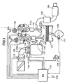
- Fig. 1 is a structural diagram of an engine for vehicle in embodiments.
- an electronically controlled throttle 104 is disposed for driving a throttle valve 103b to open and close by a throttle motor 103a.
- Air is sucked into a combustion chamber 106 via electronically controlled throttle 104 and an intake valve 105.
- a combusted exhaust gas of engine 101 is discharged from combustion chamber 106 via an exhaust valve 107, purified by a front catalyst 108 and a rear catalyst 109, and then emitted into the atmosphere.
- a valve lift amount and a valve operating angle of intake valve 105 is varied continuously by a variable valve event and lift mechanism 112a, and a phase thereof during valve opening period is varied continuously by a variable valve timing mechanism 113a. While a valve lift amount and a valve operating angle of exhaust valve 107 is varied continuously by a variable valve event and lift mechanism 112b, and a phase thereof during valve opening period is varied continuously by a variable valve timing mechanism 113b.
- An engine control unit (ECU) 114 incorporating therein a microcomputer, controls electronically controlled throttle 104, variable valve event and lift mechanism 112a and variable valve timing mechanism 113a, so that an intake air amount corresponding to an accelerator opening can be obtained.
- ECU engine control unit
- engine control unit 114 controls variable valve event and lift mechanism 112b and variable valve timing mechanism 113b for exhaust valve 107 corresponding to an open-close characteristic of intake valve 105.
- Engine control unit 114 receives various detection signals from an air flow meter 115 detecting an intake air amount Q of engine 101, an accelerator pedal sensor APS 116 detecting an opening APO of an accelerator pedal, a crank angle sensor 117 taking out a rotation signal from a crankshaft 120, a throttle sensor 118 detecting an opening TVO of throttle valve 103b, a water temperature sensor 119 detecting a cooling water temperature Tw of engine 101, and the like.
- an engine rotation speed Ne is calculated based on the rotation signal output from crank angle sensor 117.
- an electromagnetic fuel injection valve 131 is disposed on an intake port 130 at the upstream side of intake valve 105 of each cylinder.
- Fuel injection valve 131 injects fuel adjusted at a predetermined pressure toward intake valve 105 when driven to open by an injection pulse signal from engine control unit 114.
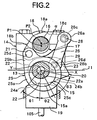
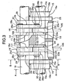
- Fig. 2 to Fig. 4 show in detail the structures of variable valve event and lift mechanisms 112a and 112b.
- Variable valve event and lift mechanism 112a on the intake valve 105 side has the same structure as that of variable valve event and lift mechanism 112b on the exhaust valve 107 side.
- variable valve event and lift mechanism 112a on the intake valve 105 side will be described, and the description of variable valve event and lift mechanism 112b on the exhaust valve 107 side will be omitted.
- variable valve event and lift mechanisms 112a and 112b for varying valve lift amounts of intake valve 105 and exhaust valve 107, respectively, are not limited to the structure as shown in Fig. 2 to Fig. 4.
- Variable valve event and lift mechanism 112 shown in Fig. 2 to Fig. 4 includes a pair of intake valves 105, 105, a camshaft (drive shaft) 13 rotatably supported by a cam bearing 14 of a cylinder head 11, two eccentric cams (drive cams) 15, 15 axially supported by camshaft 13, a control shaft 16 rotatably supported by cam bearing 14 and arranged in parallel at an upper position of camshaft 13, a pair of rocker arms 18, 18 swingingly supported by control shaft 16 through a control cam 17, and a pair of swing cams 20, 20 disposed to upper end portions of intake valves 105, 105 through valve lifters 19, 19, respectively.
- Eccentric cams 15, 15 are connected with rocker arms 18, 18 by link arms 25, 25, respectively.
- Rocker arms 18,18 are connected with swing cams 20, 20 by link members 26, 26.
- Rocker arms 18, 18, link arms 25, 25, and link members 26, 26 constitute a transmission mechanism.
- Each eccentric cam 15, as shown in Fig. 5, is formed in a substantially ring shape and includes a cam body 15a of small diameter, a flange portion 15b integrally formed on an outer surface of cam body 15a.
- An insertion hole 15c is formed through the interior of eccentric cam 15 in an axial direction, and also a center axis X of cam body 15a is biased from a center axis Y of camshaft 13 by a predetermined amount.
- Eccentric cams 15, 15 are pressed and fixed to camshaft 13 via camshaft insertion holes 15c so as to position at outsides of valve lifters 19, 19, respectively.
- Each rocker arm 18, as shown in Fig. 4, is bent and formed in a substantially crank shape, and a central base portion 18a thereof is rotatably supported by control cam 17.
- a pin hole 18d is formed through one end portion 18b which is formed to protrude from an outer end portion of base portion 18a.
- a pin 21 to be connected with a tip portion of link arm 25 is pressed into pin hole 18d.
- a pin hole 18e is formed through the other end portion 18c which is formed to protrude from an inner end portion of base portion 18a.
- a pin 28 to be connected with one end portion 26a (to be described later) of each link member 26 is pressed into pin hole 18e.
- Control cam 17 is formed in a cylindrical shape and fixed to a periphery of control shaft 16. As shown in Fig. 2, a center axis P1 position of control cam 17 is biased from a center axis P2 position of control shaft 16 by a.
- Swing cam 20 is formed in a substantially lateral U-shape as shown in Fig. 2, Fig. 6 and Fig. 7, and a supporting hole 22a is formed through a substantially ring-shaped base end portion 22.
- Camshaft 13 is inserted into supporting hole 22a to be rotatably supported.
- a pin hole 23a is formed through an end portion 23 positioned at the other end portion 18c of rocker arm 18.
- Base circular surface 24a and cam surface 24b are in contact with a predetermined position of an upper surface of each valve lifter 19 corresponding to a swing position of swing cam 20.
- a predetermined angle range ⁇ 1 of base circular surface 24a is a base circle interval and a range of from base circle interval ⁇ 1 of cam surface 24b to a predetermined angle range ⁇ 2 is a so-called ramp interval, and a range of from ramp interval ⁇ 2 of cam surface 24b to a predetermined angle range ⁇ 3 is a lift interval.
- Link arm 25 includes a ring-shaped base portion 25a and a protrusion end 25b protrudingly formed on a predetermined position of an outer surface of base portion 25a.
- a fitting hole 25c to be rotatably fitted with the outer surface of cam body 15a of eccentric cam 15 is formed on a central position of base portion 25a.
- a pin hole 25d into which pin 21 is rotatably inserted is formed through protrusion end 25b.
- Link member 26 is formed in a linear shape of predetermined length and pin insertion holes 26c, 26d are formed through both circular end portions 26a, 26b. End portions of pins 28, 29 pressed into pin hole 18d of the other end portion 18c of rocker arm 18 and pin hole 23a of end portion 23 of swing cam 20, respectively, are rotatably inserted into pin insertion holes 26c, 26d.
- Snap rings 30, 31, 32 restricting axial transfer of link arm 25 and link member 26 are disposed on respective end portions of pins 21, 28, 29.
- Control shaft 16 is driven to rotate within a predetermined angle range by a DC servo motor (actuator) 121 as shown in Fig. 10.
- DC servo motor 121 is arranged so that the rotation shaft thereof is parallel to control shaft 16, and a bevel gear 122 is axially supported by the tip portion of the rotation shaft.
- a pair of stays 123a, 123b are fixed to the tip end of control shaft 16.
- a nut 124 is swingingly supported around an axis parallel to control shaft 16 connecting the tip portions of the pair of stays 123a, 123b.
- a bevel gear 126 meshed with bevel gear 122 is axially supported at the tip end of a threaded rod 125 engaged with nut 124. Threaded rod 126 is rotated by the rotation of DC servo motor 121, and the position of nut 124 engaged with threaded rod 125 is displaced in an axial direction of threaded rod 125, so that control shaft 16 is rotated.
- valve lift amount is decreased as the position of nut 124 approaches bevel gear 126, while the valve lift amount is increased as the position of nut 124 gets away from bevel gear 126.
- a potentiometer type operating angle sensor 127 detecting the operating angle of control shaft 16 is disposed on the tip end of control shaft 16, as shown in Fig. 10.
- Control unit 114 feedback controls DC servo motor (actuator) 121 so that an actual operating angle detected by operating angle sensor 127 coincides with a target operating angle.
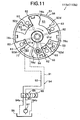
- variable valve timing mechanism 113a on intake valve 105 side and variable valve timing mechanism 113b on exhaust valve 107 side will be described based on Fig. 11.
- Variable valve timing mechanism 113a on the intake valve 105 side has the same structure as that of variable valve timing mechanism 113b on the exhaust valve 107 side.
- variable valve timing mechanisms 113a and 113b are not limited to the structure as shown in Fig. 10, and may be of a structure that varies continuously a rotation phase of camshaft relative to crankshaft.
- variable valve timing mechanisms 113a and 113b in this embodiment is a so-called vane type variable valve timing mechanism, and comprises: a cam sprocket 51 (timing sprocket) which is rotatably driven by a crankshaft 120 via a timing chain; a rotation member 53 secured to an end portion of a camshaft and rotatably housed inside cam sprocket 51; a hydraulic circuit 54 that relatively rotates rotation member 53 with respect to cam sprocket 51; and a lock mechanism 60 that selectively locks a relative rotation position between cam sprocket 51 and rotation member 53 at predetermined positions.
- a cam sprocket 51 timing sprocket
- rotation member 53 secured to an end portion of a camshaft and rotatably housed inside cam sprocket 51
- a hydraulic circuit 54 that relatively rotates rotation member 53 with respect to cam sprocket 51
- a lock mechanism 60 that selectively locks a relative rotation position between cam sprocket 51 and rotation
- Cam sprocket 51 comprises: a rotation portion (not shown in the figure) having on an outer periphery thereof, teeth for engaging with timing chain (or timing belt); a housing 56 located forward of the rotation portion, for rotatably housing rotation member 53; and a front cover and a rear cover (not shown in the figure) for closing the front and rear openings of housing 56.
- Housing 56 presents a cylindrical shape formed with both front and rear ends open and with four partition portions 63 protrudingly provided at positions on the inner peripheral face at 90° in the circumferential direction, four partition portions 63 presenting a trapezoidal shape in transverse section and being respectively provided along the axial direction of housing 56.
- Rotation member 53 is secured to the front end portion of camshaft and comprises an annular base portion 77 having four vanes 78a, 78b, 78c, and 78d provided on an outer peripheral face of base portion 77 at 90° in the circumferential direction.
- First through fourth vanes 78a to 78d present respective cross-sections of approximate trapezoidal shapes.
- the vanes are disposed in recess portions between each partition portion 63 so as to form spaces in the recess portions to the front and rear in the rotation direction.
- An advance angle side hydraulic chambers 82 and a retarded angle side hydraulic chambers 83 are thus formed.
- Lock mechanism 60 has a construction such that a lock pin 84 is inserted into an engagement hole (not shown in the figure) at a rotation position (in the reference operating condition) on the maximum retarded angle side of rotation member 53.
- Hydraulic circuit 54 has a dual system oil pressure passage, namely a first oil pressure passage 91 for supplying and discharging oil pressure with respect to advance angle side hydraulic chambers 82, and a second oil pressure passage 92 for supplying and discharging oil pressure with respect to retarded angle side hydraulic chambers 83.
- An engine driven oil pump 97 for pumping oil in an oil pan 96 is provided in supply passage 93, and the downstream ends of drain passages 94a and 94b are communicated with oil pan 96.
- First oil pressure passage 91 is formed substantially radially in a base 77 of rotation member 53, and connected to four branching paths 91 d communicating with each advance angle side hydraulic chamber 82.
- Second oil pressure passage 92 is connected to four oil galleries 92d opening to each retarded angle side hydraulic chamber 83.
- an internal spool valve is arranged so as to control the switching between respective oil pressure passages 91 and 92, and supply passage 93 and drain passages 94a and 94b.
- Engine control unit 114 controls the power supply quantity for an electromagnetic actuator 99 that drives electromagnetic switching valve 95, based on a duty control signal superimposed with a dither signal.
- rotation member 53 is rotated to the full to the advance angle side by means of vanes 78a to 78d. Due to this, the valve opening period is advanced relative to the rotation phase angle of crankshaft.
- engine control unit 114 comprises a target volume flow ratio calculating section A, an intake side VEL control section B, a throttle control section C and an exhaust side VEL control section D.
- a target volume flow ratio TQHOST target intake air amount
- a requested air amount Q0 corresponding to accelerator opening APO and engine rotation speed Ne is calculated, and also a requested ISC air amount QISC requested in an idle rotation speed control (ISC) is calculated.
- TQH 0 ST Q / ( Ne ⁇ VOL # )
- target volume flow ratio TQH0ST is corrected according to an intake negative pressure.
- a target operating angle TGVEL (intake side target valve lift amount) of control shaft 16 in intake side variable valve event and lift mechanism 112a is calculated, based on a post-corrected target volume flow ratio TQH0VEL and a correction value based on valve timing controlled by variable valve timing mechanism 113a.
- DC servo motor 121 in variable valve event and lift mechanism 112a is feedback controlled, so that an actual operating angle coincides with intake side target operating angle TGVEL (intake side target valve lift amount).
- a volume flow ratio requested for throttle valve 103b is calculated to control the intake negative pressure to be constant.
- intake side target operating angle TGVEL is controlled to be equal to or above a minimum lift amount (minimum operating angle) in variable valve event and lift mechanism 112a.
- a smaller one is selected from the volume flow ratio for controlling the intake negative pressure to be constant and the volume flow ratio for compensating for an excess portion of volume flow ratio controlled by intake valve 105, and the selected volume flow ratio is converted into a target angle TGTVO of throttle valve 103b.
- throttle motor 103a is feedback controlled so that an angle (opening) of throttle valve 103b coincides with target angle TGTVO.
- FIG. 13 shows the detail of intake side VEL control section B.
- Target volume flow ratio TQH0ST is corrected by a correction value KMNIQH0 according to the intake negative pressure (valve upstream pressure).
- a larger one is selected from a post-corrected target volume flow ratio TQH0VEL0 and a minimum volume flow ratio QH0LMT controllable by means of a valve lift amount control by variable valve event and lift mechanism 112a, to be output as target volume flow ratio TQH0VEL.
- a throttle amount of throttle valve 103b is set for obtaining target volume flow ratio TQH0VEL in throttle control section B.
- the volume flow ratio is controlled to target volume flow ratio TQH0VEL.
- Target volume flow ratio TQH0VEL is converted into a state amount VAACDNV, and further multiplied by engine rotation speed Ne and discharge amount (entire cylinder volume) VOL#, to be converted into an entire opening area TVLAACD requested for intake valve 105.
- Entire opening area TVELAACD is corrected based on a valve lift amount VELCOM, and flow loss coefficients Cd and KAVTC according to valve timing, to be output as a requested opening area TVELAA, and further converted into target operating angle TGVEL
- target operating angle TGVEL is subjected to a limitation according to valve timing VTCNOW by variable valve timing mechanism 113a.
- DC servo motor 121 in variable valve event and lift mechanism 112a is feedback controlled.
- opening timing IVOREAL of intake valve 105 is calculated based on an actual operating angle VCS-ANGL as a control result and valve timing VTCNOW, to be output to exhaust side VEL control section D.
- variable valve timing mechanisms 113a and 113b are controlled according to an engine load (target volume flow ratio TQH0ST) and engine rotation speed.
- FIG.14 A block diagram in Fig.14 shows the detail of exhaust side VEL control section D, that controls variable valve event lift mechanism 112b and variable valve timing mechanism 113b on the exhaust side.
- a first minimum valve lift amount TGEVLLL0 is set according to engine rotation speed Ne, and also a second minimum valve lift amount TGEVLLL1 is set based on target volume flow ratio TQH0ST.
- a larger one in first minimum valve lift amount TGEVLLL0 and second minimum valve lift amount TGEVLLL1 is output as a minimum valve lift amount (minimum operating angle) TGEVLLL of exhaust valve 107.
- First minimum valve lift amount TGEVLLL0 is set to be a larger value as engine rotation speed Ne is higher.
- variable valve event and lift mechanisms 112a and 112b in this embodiment since an allowable rotation speed is lower as the valve lift amount is smaller, if a high rotation operation is performed under a state of low valve lift amount, there may occur a failure of mechanism.
- valve lift amount is limited to be equal to or above an amount having durability to engine rotation speed Ne, by first minimum valve lift amount TGEVLLL0.
- second minimum valve lift amount TGEVLLL1 is a minimum valve lift amount required for gas exchange at target volume flow ratio TQH0ST.
- a maximum valve lift amount (maximum operating angle) of exhaust valve 107 is set based on opening timing IVO of intake valve 105.
- a retarded angle side limit value EVCLIM0 (refer to Fig. 15) at closing timing EVC of exhaust valve 107 in the case where valve timing of exhaust valve 107 is controlled to the most retarded angle side is calculated.
- a maximum valve lift amount (maximum operating angle) TGEVELLH is set.
- maximum valve lift amount (maximum operating angle) TGEVELLH is the valve lift (operating angle) wherein closing timing EVC of exhaust valve 107 reaches retarded angle side limit value EVCLIM0 at the valve timing at that time, and becomes larger as the valve timing is further advanced (refer to Fig. 15).
- closing timing EVC is limited to maximum valve lift amount (maximum operating angle) TGEVELLH or less, closing timing EVC is not delayed than retarded side limit value EVCLIM0. Thereby, a valve overlap amount is restricted within an allowable value, to avoid valve interference or degradation of combustibility.
- Exhaust side VEL limiter control section is input with target operating angle TGEVEL0 of exhaust valve 107 obtained by converting requested opening area TVELAA, minimum valve lift amount (minimum operating angle) TGEVLLL and maximum valve lift amount (maximum operating angle) TGEVELLH.
- exhaust side VEL limiter control section outputs minimum valve lift amount (minimum operating angle) TGEVLLL as target operating angle TGEVEL.
- target operating angle TGEVEL0 exceeds maximum valve lift amount (maximum operating angle) TGEVLLH
- maximum valve lift amount (maximum operating angle) TGEVLLH is output as target operating angle TGEVEL.
- target operating angle TGEVEL0 is more than minimum valve lift amount (minimum operating angle). TGEVLLL and also less than maximum valve lift amount (maximum operating angle) TGEVLLH, target operating angle TGEVEL0 is output as it is, as target operating angle TGEVEL.
- DC servo motor 121 in exhaust side variable valve event and lift mechanism 112b is feedback controlled.
- target operating angle TGEVEL is limited by maximum valve lift amount (maximum operating angle) TGEVELLH, an opening area of exhaust valve corresponding to target volume flow ratio TQH0ST cannot be obtained, and there occurs a possibility of failure in variable valve event and lift mechanism 112b.
- valve timing of exhaust valve 107 is corrected to be advanced, since a center position of opening period of exhaust valve 107 is advanced, an angle of from the center position of opening period to retarded angle side limit value EVCLIM0 becomes larger, so that maximum valve lift amount (maximum operating angle) with retarded angle side limit value EVCLlM0 as closing timing EVC is set to be larger (refer to Fig. 15).
Landscapes
- Engineering & Computer Science (AREA)
- Mechanical Engineering (AREA)
- General Engineering & Computer Science (AREA)
- Chemical & Material Sciences (AREA)
- Combustion & Propulsion (AREA)
- Output Control And Ontrol Of Special Type Engine (AREA)
- Valve Device For Special Equipments (AREA)
- Electrical Control Of Air Or Fuel Supplied To Internal-Combustion Engine (AREA)
Claims (18)
- Appareil de contrôle de soupape à ouverture variable destiné à un moteur à combustion interne (101), afin de faire varier des caractéristiques d'ouverture/fermeture d'une soupape d'admission (105) et d'une soupape d'échappement (107), ledit appareil comprenant :un mécanisme de soupape à ouverture variable de côté admission (112a, 113a) qui fait varier la caractéristique d'ouverture/fermeture de ladite soupape d'admission (105) ;un mécanisme de soupape à ouverture variable de côté échappement (112b, 113b) qui fait varier la caractéristique d'ouverture/fermeture de ladite soupape d'échappement (107) ;un détecteur de condition d'exploitation (115, 116, 117, 118, 119) qui détecte les conditions d'exploitation dudit moteur à combustion interne (101) ;une unité de commande (114) qui reçoit un signal de détection (Q, APO, Ne, TVO, Tw) de la part dudit détecteur de condition d'exploitation (115, 116, 117, 118, 119), et qui détermine la caractéristique d'ouverture/fermeture de ladite soupape d'admission (105) sur la base des conditions d'exploitation dudit moteur à combustion interne (101) afin de contrôler ledit mécanisme de soupape à ouverture variable de côté admission (112a, 113a), et qui détermine également la caractéristique d'ouverture/fermeture de ladite soupape d'échappement (107) sur la base des conditions d'exploitation dudit moteur à combustion interne (101) afin de contrôler ledit mécanisme de soupape à ouverture variable de côté échappement (112b, 113b), et qui transmet des signaux de commande audit mécanisme de soupape à ouverture variable de côté admission (112a, 113a) et audit mécanisme de soupape à ouverture variable de côté échappement (112b, 113b),ledit appareil étant caractérisé en ce que ladite unité de commande (114) ajoute une restriction à la caractéristique d'ouverture/fermeture de ladite soupape d'échappement (107) selon la caractéristique d'ouverture/fermeture de ladite soupape d'admission (105) afin de contrôler ledit mécanisme de soupape à ouverture variable de côté admission (112b, 113b).
- Appareil de contrôle de soupape à ouverture variable destiné à un moteur à combustion interne selon la revendication 1, dans lequel ladite unité de commande définit une position angulaire la plus retardée du moment de fermeture de ladite soupape d'échappement (107), sur la base d'un moment d'ouverture de ladite soupape d'admission (105), et contrôle le moment de fermeture de ladite soupape d'échappement (107) selon un angle plus avancé que ladite position angulaire la plus retardée.
- Appareil de contrôle de soupape à ouverture variable destiné à un moteur à combustion interne selon la revendication 2, dans lequel ledit mécanisme de soupape à ouverture variable de côté échappement (112b, 113b) comprend une soupape à ouverture variable et un mécanisme de levage (112b) qui fait varier une quantité de levage de la soupape ainsi qu'un angle d'exploitation de soupape de ladite soupape d'échappement (107), et
ladite unité de commande (114) calcule une quantité de levage de soupape maximale selon laquelle le moment de fermeture de ladite soupape d'échappement (107) devient ladite position angulaire la plus retardée, et limite la quantité de levage de soupape de ladite soupape d'échappement (107) à l'aide de ladite soupape à ouverture variable et dudit mécanisme de levage (112b) de telle sorte qu'elle soit égale ou inférieure à ladite quantité de levage de soupape maximale. - Appareil de contrôle de soupape à ouverture variable destiné à un moteur à combustion interne selon la revendication 2, dans lequel ledit mécanisme de soupape à ouverture variable de côté échappement (112b, 113b) comprend une soupape à ouverture variable et un mécanisme de levage (112b) qui fait varier une quantité de levage de soupape ainsi qu'un angle d'exploitation de soupape de ladite soupape d'échappement (107), et
ladite unité de commande (114) limite la quantité de levage de soupape de ladite soupape d'échappement (107) à l'aide de ladite soupape à ouverture variable et dudit mécanisme de levage de telle sorte qu'elle soit égale ou inférieure à ladite quantité de levage de soupape maximale, mais également supérieure ou égale à une quantité de levage de soupape minimale prédéterminée. - Appareil de contrôle de soupape à ouverture variable destiné à un moteur à combustion interne selon la revendication 4, dans lequel ledit mécanisme de soupape à ouverture variable de côté échappement (112b, 113b) comprend, en plus de ladite soupape à ouverture variable et dudit mécanisme de levage (112b), un mécanisme de synchronisation de soupape à ouverture variable (113b) qui fait varier la synchronisation de ladite soupape d'échappement (107), au niveau de l'angle d'exploitation de soupape, à l'aide de ladite soupape à ouverture variable et dudit mécanisme de levage (112b), et
ladite unité de commande (114) fait avancer la synchronisation de ladite soupape d'échappement (107) à l'aide dudit mécanisme de synchronisation de soupape à ouverture variable (113b) afin de contrôler ladite quantité de levage de soupape maximale de telle sorte qu'elle soit égale ou supérieure à ladite quantité de levage de soupape minimale prédéterminée, lorsque ladite quantité de levage de soupape maximale est inférieure à ladite quantité de levage de soupape minimale prédéterminée. - Appareil de contrôle de soupape à ouverture variable destiné à un moteur à combustion interne selon la revendication 4, dans lequel ladite unité de commande (114) définit ladite quantité de levage de soupape minimale prédéterminée selon une vitesse de rotation du moteur.
- Appareil de contrôle de soupape à ouverture variable destiné à un moteur à combustion interne selon la revendication 4, dans lequel ladite unité de commande (114) calcule une quantité d'air d'admission cible sur la base des conditions d'exploitation du moteur à combustion interne (101), afin de contrôler ledit mécanisme de soupape à ouverture variable de côté admission (112a, 113a) sur la base de ladite quantité d'air d'admission cible, et définit également ladite quantité de levage de soupape minimale prédéterminée selon ladite quantité d'air d'admission cible.
- Appareil de contrôle de soupape à ouverture variable destiné à un moteur à combustion interne selon la revendication 1, dans lequel ladite unité de commande (114) calcule une quantité d'air d'admission cible sur la base des conditions d'exploitation du moteur à combustion interne (101), afin de contrôler ledit mécanisme de soupape à ouverture variable de côté admission (112a, 113a) sur la base de ladite quantité d'air d'admission cible.
- Appareil de contrôle de soupape à ouverture variable destiné à un moteur à combustion interne selon la revendication 1, dans lequel ledit mécanisme de soupape à ouverture variable de côté admission (112a, 113a) et ledit mécanisme de soupape à ouverture variable de côté échappement (112b, 113b) comprennent chacun une soupape à ouverture variable et un mécanisme de levage (112a, 112b) qui fait varier une quantité de levage de soupape ainsi qu'un angle d'exploitation de soupape, ladite soupape à ouverture variable et ledit mécanisme de levage (112a, 112b) comprennent :un arbre d'entraînement (13) tournant en synchronisme avec un vilebrequin (120) ;une came d'entraînement (15) fixée sur ledit arbre d'entraînement (13) ;une came pivotante (20) pivotant afin d'actionner lesdites soupapes (105, 107) de telle sorte qu'elles s'ouvrent et se ferment ;un mécanisme de transmission (18, 25, 26) ayant une extrémité reliée à ladite came de commande (15) et l'autre extrémité reliée à ladite came pivotante (20) ;un arbre de commande (16) possédant une came de commande (17) changeant la position dudit mécanisme de transmission (18, 25, 26) ; etun actionneur (21) tournant ledit arbre de commande (16), et modifiant de manière continue la quantité de levage de soupape ainsi que l'angle d'exploitation de soupape en contrôlant de manière rotative ledit arbre de commande (16) à l'aide dudit actionneur (21).
- Procédé de contrôle de soupape à ouverture variable destiné à un moteur à combustion interne, afin de contrôler un mécanisme de soupape à ouverture variable de côté admission (112a, 113a) qui fait varier une caractéristique d'ouverture/fermeture d'une soupape d'admission (105), et un mécanisme de soupape à ouverture variable de côté échappement (112b, 113b) qui fait varier une caractéristique d'ouverture/fermeture d'une soupape d'échappement (107), caractérisé en ce qu'il comprend les étapes consistant à :détecter les conditions d'exploitation dudit moteur à combustion interne (101) ;déterminer la caractéristique d'ouverture/fermeture de ladite soupape d'admission (105) sur la base des conditions d'exploitation dudit moteur à combustion interne (101) ;contrôler ledit mécanisme de soupape à ouverture variable de côté admission (112a, 113a) selon la caractéristique d'ouverture/fermeture ;déterminer la caractéristique d'ouverture/fermeture de ladite soupape d'échappement (107) sur la base des conditions d'exploitation dudit moteur à combustion interne (101) ;ajouter une restriction à la caractéristique d'ouverture/fermeture de ladite soupape d'échappement (107) selon la caractéristique d'ouverture/fermeture de ladite soupape d'admission (105) ;contrôler ledit mécanisme de soupape à ouverture variable de côté échappement (112b, 113b) selon la caractéristique d'ouverture/fermeture limitée de ladite soupape d'échappement (107) .
- Procédé de contrôle d'une soupape à ouverture variable destiné à un moteur à combustion interne selon la revendication 10, dans lequel ladite étape d'ajout d'une restriction à la caractéristique d'ouverture/fermeture de ladite soupape d'échappement (107) comprend les étapes consistant à :définir une position angulaire la plus retardée du moment de fermeture de ladite soupape d'échappement (107), sur la base du moment d'ouverture de ladite soupape d'admission (105) ; et contrôler le moment de fermeture de ladite soupape d'échappement (107) selon un angle plus avancé que ladite position angulaire la plus retardée.
- Procédé de contrôle d'une soupape à ouverture variable destiné à un moteur à combustion interne selon la revendication 11, dans lequel ledit mécanisme de soupape à ouverture variable de côté échappement (112b, 113b) comprend une soupape à ouverture variable et un mécanisme de levage (112b) qui fait varier une quantité de levage de la soupape ainsi qu'un angle d'exploitation de soupape de ladite soupape d'échappement (107), et
ladite étape de contrôle du moment de fermeture de ladite soupape d'échappement (107) comprend les étapes consistant à :calculer une quantité de levage de soupape maximale selon laquelle le moment de fermeture de ladite soupape d'échappement (107) devient ladite position angulaire la plus retardée ; etlimiter la quantité de levage de soupape de ladite soupape d'échappement (107) à l'aide de ladite soupape à ouverture variable et dudit mécanisme de levage (112b) afin qu'elle soit égale ou inférieure à ladite quantité de levage maximale. - Procédé de contrôle d'une soupape à ouverture variable destiné à un moteur à combustion interne selon la revendication 11, dans lequel ledit Procédé de contrôle d'une soupape à ouverture variable destiné à un moteur à combustion interne selon la revendication 11, dans lequel ledit mécanisme de soupape à ouverture variable de côté échappement (112b, 113b) comprend une soupape à ouverture variable et un mécanisme de levage (112b) qui fait varier une quantité de levage de soupape ainsi qu'un angle d'exploitation de soupape de ladite soupape d'échappement (107), et
ladite étape de contrôle du moment de fermeture de ladite soupape d'échappement (107) comprend les étapes consistant à :calculer une quantité de levage de soupape maximale selon laquelle le moment de fermeture de ladite soupape d'échappement (107) devient ladite position angulaire la plus retardée ; etlimiter la quantité de levage de soupape de ladite soupape d'échappement (107) à l'aide de ladite soupape à ouverture variable et dudit mécanisme de levage (112b) afin qu'elle soit égale ou inférieure à ladite quantité de levage maximale, mais également égale ou supérieure à une quantité de levage de soupape minimale prédéterminée. - Procédé de contrôle d'une soupape à ouverture variable destiné à un moteur à combustion interne selon la revendication 13, dans lequel ledit mécanisme de soupape à ouverture variable de côté échappement (112b, 113b) comprend, en plus de ladite soupape à ouverture variable et dudit mécanisme de levage (112b), un mécanisme de synchronisation de soupape à ouverture variable (113b) qui fait varier la synchronisation de ladite soupape d'échappement (107), au niveau de l'angle d'exploitation de soupape, à l'aide de ladite soupape à ouverture variable et dudit mécanisme de levage (112b), et
ladite étape de calcul de la quantité de levage de soupape maximale comprend les étapes consistant à :contrôler ledit mécanisme de synchronisation de soupape à ouverture variable (113b) afin de faire avancer la synchronisation de ladite soupape d'échappement (107), lorsque ladite quantité de levage de soupape maximale est inférieure à ladite quantité de levage de soupape minimale prédéterminée ; etcalculer la quantité de levage de soupape maximale selon laquelle le moment de fermeture de ladite soupape d'échappement (107) devient ladite position angulaire la plus retardée, dans une condition dans laquelle la synchronisation de ladite soupape d'échappement (107) est avancée. - Procédé de contrôle d'une soupape à ouverture variable destiné à un moteur à combustion interne selon la revendication 13, dans lequel ladite étape de limitation de la quantité de levage de soupape de ladite soupape d'échappement (107) comprend l'étape consistant à :définir ladite quantité de levage de soupape minimale prédéterminée selon une vitesse de rotation du moteur.
- Procédé de contrôle d'une soupape à ouverture variable destiné à un moteur à combustion interne selon la revendication 13, dans lequel ladite étape de détermination e la caractéristique d'ouverture/fermeture de ladite soupape d'admission (105) comprend les étapes consistant à :calculer une quantité d'air d'admission cible sur la base des conditions d'exploitation du moteur à combustion interne (101) ; etdéterminer la caractéristique d'ouverture/fermeture de ladite soupape d'admission (105) sur la base de ladite quantité d'air d'admission cible, etladite étape de limitation de la quantité de levage de soupape de ladite soupape d'échappement (107) comprend l'étape consistant à :définir ladite quantité de levage de soupape minimale prédéterminée selon ladite quantité d'air d'admission cible.
- Procédé de contrôle d'une soupape à ouverture variable destiné à un moteur à combustion interne selon la revendication 10, dans lequel ladite étape de détermination de la caractéristique d'ouverture/fermeture de ladite soupape d'admission (105) comprend les étapes consistant à :calculer une quantité d'air d'admission cible sur la base des conditions d'exploitation du moteur à combustion interne (101) ; etdéterminer la caractéristique d'ouverture/fermeture de ladite soupape d'admission (105) sur la base de ladite quantité d'air d'admission cible.
- Procédé de contrôle d'une soupape à ouverture variable destiné à un moteur à combustion interne selon la revendication 10, dans lequel ledit mécanisme de soupape à ouverture variable de côté admission (112a, 113a) et ledit mécanisme de soupape à ouverture variable de côté échappement (112b, 113b) comprennent chacun une soupape à ouverture variable et un mécanisme de levage (112a, 112b) qui fait varier une quantité de levage de soupape ainsi qu'un angle d'exploitation de soupape,
ladite soupape à ouverture variable et ledit mécanisme de levage (112a, 112b) comprenant :un arbre d'entraînement (13) tournant en synchronisme avec un vilebrequin (120) ;une came d'entraînement (15) fixée sur ledit arbre d'entraînement (13) ;une came pivotante (20) pivotant afin d'actionner lesdites soupapes (105, 107) de telle sorte qu'elles s'ouvrent et se ferment ;un mécanisme de transmission (18, 25, 26) ayant une extrémité reliée à ladite came de commande (15) et l'autre extrémité reliée à ladite came pivotante (20) ;un arbre de commande (16) possédant une came de commande (17) changeant la position dudit mécanisme de transmission (18, 25, 26) ; etun actionneur (21) tournant ledit arbre de commande (16), et modifiant de manière continue la quantité de levage de soupape ainsi que l'angle d'exploitation de soupape en contrôlant de manière rotative ledit arbre de commande (16) à l'aide dudit actionneur (21).
Applications Claiming Priority (2)
| Application Number | Priority Date | Filing Date | Title |
|---|---|---|---|
| JP2001331353A JP4024032B2 (ja) | 2001-10-29 | 2001-10-29 | 内燃機関の可変バルブ制御装置 |
| JP2001331353 | 2001-10-29 |
Publications (3)
| Publication Number | Publication Date |
|---|---|
| EP1306529A2 EP1306529A2 (fr) | 2003-05-02 |
| EP1306529A3 EP1306529A3 (fr) | 2003-12-10 |
| EP1306529B1 true EP1306529B1 (fr) | 2006-03-22 |
Family
ID=19146948
Family Applications (1)
| Application Number | Title | Priority Date | Filing Date |
|---|---|---|---|
| EP02024043A Expired - Lifetime EP1306529B1 (fr) | 2001-10-29 | 2002-10-28 | Appareil de contrôle d'ouverture variable de soupapes pour moteur à combustion interne et méthode correspondante |
Country Status (4)
| Country | Link |
|---|---|
| US (1) | US6612274B2 (fr) |
| EP (1) | EP1306529B1 (fr) |
| JP (1) | JP4024032B2 (fr) |
| DE (1) | DE60209981T2 (fr) |
Families Citing this family (14)
| Publication number | Priority date | Publication date | Assignee | Title |
|---|---|---|---|---|
| JP2003129871A (ja) * | 2001-10-23 | 2003-05-08 | Hitachi Unisia Automotive Ltd | 内燃機関の可変バルブ制御装置 |
| US7013211B2 (en) * | 2002-12-02 | 2006-03-14 | Hitachi, Ltd. | Variable valve control apparatus for internal combustion engine and method thereof |
| FR2849465B1 (fr) * | 2002-12-27 | 2006-11-03 | Renault Sa | Dispositif de commande de soupape de moteur a combustion interne, a levee variable |
| JP4082596B2 (ja) * | 2003-07-07 | 2008-04-30 | 本田技研工業株式会社 | 制御装置 |
| CN100425813C (zh) * | 2004-05-24 | 2008-10-15 | 株式会社日立制作所 | 用于内燃机的可变气门控制装置及其控制方法 |
| JP2006183480A (ja) * | 2004-12-27 | 2006-07-13 | Nissan Motor Co Ltd | ユニフロー2ストローク内燃機関 |
| JP2007332942A (ja) * | 2006-06-19 | 2007-12-27 | Hitachi Ltd | 内燃機関の可変動弁制御装置 |
| JP5088044B2 (ja) * | 2007-08-20 | 2012-12-05 | 日産自動車株式会社 | エンジンの制御装置 |
| US8155862B2 (en) * | 2008-02-28 | 2012-04-10 | Mazda Motor Corporation | Internal combustion engine control method and internal combustion engine system |
| JP5273306B2 (ja) * | 2010-07-05 | 2013-08-28 | トヨタ自動車株式会社 | 内燃機関の制御装置 |
| JP5257628B2 (ja) * | 2010-09-02 | 2013-08-07 | 株式会社デンソー | 可変バルブタイミング制御装置 |
| KR101461891B1 (ko) * | 2013-02-20 | 2014-11-14 | 현대자동차 주식회사 | 배기가스 연소 장치 |
| KR101448794B1 (ko) | 2013-07-02 | 2014-10-08 | 현대자동차 주식회사 | 오일 컨트롤 밸브의 전류 제어에 따른 연속 가변 밸브 타이밍 제어 방법 |
| JP6252995B2 (ja) * | 2016-03-14 | 2017-12-27 | マツダ株式会社 | エンジンの制御装置 |
Family Cites Families (9)
| Publication number | Priority date | Publication date | Assignee | Title |
|---|---|---|---|---|
| US5732669A (en) * | 1992-12-13 | 1998-03-31 | Bayerische Motoren Werke Aktiengesellschaft | Valve control for an internal combustion engine |
| JPH06272580A (ja) | 1993-03-18 | 1994-09-27 | Fujitsu Ten Ltd | 内燃機関のバルブタイミングの制御方法 |
| JP3119050B2 (ja) * | 1993-09-28 | 2000-12-18 | トヨタ自動車株式会社 | 内燃機関のバルブタイミング制御装置 |
| JP3632424B2 (ja) * | 1998-01-30 | 2005-03-23 | トヨタ自動車株式会社 | 内燃機関のバルブ開閉特性制御装置 |
| JP2000008931A (ja) * | 1998-06-19 | 2000-01-11 | Hitachi Ltd | 電磁駆動式吸排気バルブを備えたエンジンの制御装置 |
| JP2000291419A (ja) * | 1999-04-08 | 2000-10-17 | Unisia Jecs Corp | 内燃機関の可変動弁装置 |
| JP3290422B2 (ja) * | 1999-04-26 | 2002-06-10 | 三菱電機株式会社 | 内燃機関のバルブタイミング制御装置 |
| JP3975246B2 (ja) | 1999-06-23 | 2007-09-12 | 株式会社日立製作所 | 内燃機関の可変動弁装置 |
| JP3975652B2 (ja) * | 2000-06-09 | 2007-09-12 | 日産自動車株式会社 | 内燃機関の可変動弁装置 |
-
2001
- 2001-10-29 JP JP2001331353A patent/JP4024032B2/ja not_active Expired - Fee Related
-
2002
- 2002-10-25 US US10/279,912 patent/US6612274B2/en not_active Expired - Lifetime
- 2002-10-28 EP EP02024043A patent/EP1306529B1/fr not_active Expired - Lifetime
- 2002-10-28 DE DE60209981T patent/DE60209981T2/de not_active Expired - Lifetime
Also Published As
| Publication number | Publication date |
|---|---|
| JP2003138950A (ja) | 2003-05-14 |
| US6612274B2 (en) | 2003-09-02 |
| DE60209981D1 (de) | 2006-05-11 |
| DE60209981T2 (de) | 2006-08-17 |
| JP4024032B2 (ja) | 2007-12-19 |
| US20030079703A1 (en) | 2003-05-01 |
| EP1306529A2 (fr) | 2003-05-02 |
| EP1306529A3 (fr) | 2003-12-10 |
Similar Documents
| Publication | Publication Date | Title |
|---|---|---|
| EP1306529B1 (fr) | Appareil de contrôle d'ouverture variable de soupapes pour moteur à combustion interne et méthode correspondante | |
| US7017551B2 (en) | Intake control apparatus for internal combustion engine and method thereof | |
| US6920851B2 (en) | Variable valve control apparatus for internal combustion engine and method thereof | |
| US6851409B2 (en) | Apparatus and method for controlling intake air amount of internal combustion engine | |
| US6945224B2 (en) | Intake air amount control apparatus for vehicle engine and method thereof | |
| US7386390B2 (en) | Variable valve control apparatus for internal combustion engine and method thereof | |
| US6874472B2 (en) | Ignition timing control apparatus for internal combustion engine and method thereof | |
| US6843230B2 (en) | Control apparatus and control method of internal combustion engine | |
| US7013875B2 (en) | Apparatus for controlling fuel injection of engine and method thereof | |
| EP1306528B1 (fr) | Dispositif de commande de soupape variable pour un moteur et méthode | |
| US7055474B2 (en) | Variable valve control apparatus for internal combustion engine and method thereof | |
| JP4359672B2 (ja) | 内燃機関の可変動弁制御装置 | |
| JP4188629B2 (ja) | エンジンの吸気制御装置 | |
| JP4027636B2 (ja) | 内燃機関の吸入空気量制御装置 | |
| JP2005214168A (ja) | 内燃機関の可変動弁制御装置 | |
| JP4125919B2 (ja) | エンジンの燃料噴射装置 | |
| JP2004183597A (ja) | 内燃機関の可変動弁装置 | |
| JP2004169573A (ja) | 内燃機関の吸入空気量制御装置 | |
| JP2005232985A (ja) | 内燃機関の可変動弁制御装置 |
Legal Events
| Date | Code | Title | Description |
|---|---|---|---|
| PUAI | Public reference made under article 153(3) epc to a published international application that has entered the european phase |
Free format text: ORIGINAL CODE: 0009012 |
|
| AK | Designated contracting states |
Designated state(s): AT BE BG CH CY CZ DE DK EE ES FI FR GB GR IE IT LI LU MC NL PT SE SK TR |
|
| AX | Request for extension of the european patent |
Extension state: AL LT LV MK RO SI |
|
| PUAL | Search report despatched |
Free format text: ORIGINAL CODE: 0009013 |
|
| AK | Designated contracting states |
Kind code of ref document: A3 Designated state(s): AT BE BG CH CY CZ DE DK EE ES FI FR GB GR IE IT LI LU MC NL PT SE SK TR |
|
| AX | Request for extension of the european patent |
Extension state: AL LT LV MK RO SI |
|
| 17P | Request for examination filed |
Effective date: 20040521 |
|
| 17Q | First examination report despatched |
Effective date: 20040629 |
|
| AKX | Designation fees paid |
Designated state(s): DE FR |
|
| RAP1 | Party data changed (applicant data changed or rights of an application transferred) |
Owner name: HITACHI, LTD. |
|
| GRAP | Despatch of communication of intention to grant a patent |
Free format text: ORIGINAL CODE: EPIDOSNIGR1 |
|
| GRAS | Grant fee paid |
Free format text: ORIGINAL CODE: EPIDOSNIGR3 |
|
| GRAA | (expected) grant |
Free format text: ORIGINAL CODE: 0009210 |
|
| AK | Designated contracting states |
Kind code of ref document: B1 Designated state(s): DE FR |
|
| REF | Corresponds to: |
Ref document number: 60209981 Country of ref document: DE Date of ref document: 20060511 Kind code of ref document: P |
|
| ET | Fr: translation filed | ||
| PLBE | No opposition filed within time limit |
Free format text: ORIGINAL CODE: 0009261 |
|
| STAA | Information on the status of an ep patent application or granted ep patent |
Free format text: STATUS: NO OPPOSITION FILED WITHIN TIME LIMIT |
|
| 26N | No opposition filed |
Effective date: 20061227 |
|
| PGFP | Annual fee paid to national office [announced via postgrant information from national office to epo] |
Ref country code: FR Payment date: 20141008 Year of fee payment: 13 Ref country code: DE Payment date: 20141023 Year of fee payment: 13 |
|
| REG | Reference to a national code |
Ref country code: DE Ref legal event code: R119 Ref document number: 60209981 Country of ref document: DE |
|
| PG25 | Lapsed in a contracting state [announced via postgrant information from national office to epo] |
Ref country code: DE Free format text: LAPSE BECAUSE OF NON-PAYMENT OF DUE FEES Effective date: 20160503 |
|
| REG | Reference to a national code |
Ref country code: FR Ref legal event code: ST Effective date: 20160630 |
|
| PG25 | Lapsed in a contracting state [announced via postgrant information from national office to epo] |
Ref country code: FR Free format text: LAPSE BECAUSE OF NON-PAYMENT OF DUE FEES Effective date: 20151102 |