EP1306545A2 - Soupape électromagnétique de commande d'une soupape d'injection - Google Patents
Soupape électromagnétique de commande d'une soupape d'injection Download PDFInfo
- Publication number
- EP1306545A2 EP1306545A2 EP02022596A EP02022596A EP1306545A2 EP 1306545 A2 EP1306545 A2 EP 1306545A2 EP 02022596 A EP02022596 A EP 02022596A EP 02022596 A EP02022596 A EP 02022596A EP 1306545 A2 EP1306545 A2 EP 1306545A2
- Authority
- EP
- European Patent Office
- Prior art keywords
- bore
- section
- valve
- solenoid valve
- sections
- Prior art date
- Legal status (The legal status is an assumption and is not a legal conclusion. Google has not performed a legal analysis and makes no representation as to the accuracy of the status listed.)
- Withdrawn
Links
- 238000002347 injection Methods 0.000 title claims description 12
- 239000007924 injection Substances 0.000 title claims description 12
- 239000000446 fuel Substances 0.000 claims abstract description 9
- 230000007704 transition Effects 0.000 claims description 13
- 239000012530 fluid Substances 0.000 claims description 7
- 238000004891 communication Methods 0.000 claims description 2
- 230000015572 biosynthetic process Effects 0.000 description 4
- 238000005553 drilling Methods 0.000 description 4
- 230000002349 favourable effect Effects 0.000 description 3
- 238000004519 manufacturing process Methods 0.000 description 2
- 238000000034 method Methods 0.000 description 2
- XLYOFNOQVPJJNP-UHFFFAOYSA-N water Substances O XLYOFNOQVPJJNP-UHFFFAOYSA-N 0.000 description 2
- 230000007423 decrease Effects 0.000 description 1
- 230000003292 diminished effect Effects 0.000 description 1
- 230000000694 effects Effects 0.000 description 1
- 239000007788 liquid Substances 0.000 description 1
- 238000011144 upstream manufacturing Methods 0.000 description 1
Images
Classifications
-
- F—MECHANICAL ENGINEERING; LIGHTING; HEATING; WEAPONS; BLASTING
- F02—COMBUSTION ENGINES; HOT-GAS OR COMBUSTION-PRODUCT ENGINE PLANTS
- F02M—SUPPLYING COMBUSTION ENGINES IN GENERAL WITH COMBUSTIBLE MIXTURES OR CONSTITUENTS THEREOF
- F02M47/00—Fuel-injection apparatus operated cyclically with fuel-injection valves actuated by fluid pressure
- F02M47/02—Fuel-injection apparatus operated cyclically with fuel-injection valves actuated by fluid pressure of accumulator-injector type, i.e. having fuel pressure of accumulator tending to open, and fuel pressure in other chamber tending to close, injection valves and having means for periodically releasing that closing pressure
- F02M47/027—Electrically actuated valves draining the chamber to release the closing pressure
-
- F—MECHANICAL ENGINEERING; LIGHTING; HEATING; WEAPONS; BLASTING
- F02—COMBUSTION ENGINES; HOT-GAS OR COMBUSTION-PRODUCT ENGINE PLANTS
- F02M—SUPPLYING COMBUSTION ENGINES IN GENERAL WITH COMBUSTIBLE MIXTURES OR CONSTITUENTS THEREOF
- F02M61/00—Fuel-injectors not provided for in groups F02M39/00 - F02M57/00 or F02M67/00
- F02M61/16—Details not provided for in, or of interest apart from, the apparatus of groups F02M61/02 - F02M61/14
- F02M61/168—Assembling; Disassembling; Manufacturing; Adjusting
-
- F—MECHANICAL ENGINEERING; LIGHTING; HEATING; WEAPONS; BLASTING
- F02—COMBUSTION ENGINES; HOT-GAS OR COMBUSTION-PRODUCT ENGINE PLANTS
- F02M—SUPPLYING COMBUSTION ENGINES IN GENERAL WITH COMBUSTIBLE MIXTURES OR CONSTITUENTS THEREOF
- F02M2200/00—Details of fuel-injection apparatus, not otherwise provided for
- F02M2200/04—Fuel-injection apparatus having means for avoiding effect of cavitation, e.g. erosion
-
- F—MECHANICAL ENGINEERING; LIGHTING; HEATING; WEAPONS; BLASTING
- F02—COMBUSTION ENGINES; HOT-GAS OR COMBUSTION-PRODUCT ENGINE PLANTS
- F02M—SUPPLYING COMBUSTION ENGINES IN GENERAL WITH COMBUSTIBLE MIXTURES OR CONSTITUENTS THEREOF
- F02M2200/00—Details of fuel-injection apparatus, not otherwise provided for
- F02M2200/28—Details of throttles in fuel-injection apparatus
-
- F—MECHANICAL ENGINEERING; LIGHTING; HEATING; WEAPONS; BLASTING
- F02—COMBUSTION ENGINES; HOT-GAS OR COMBUSTION-PRODUCT ENGINE PLANTS
- F02M—SUPPLYING COMBUSTION ENGINES IN GENERAL WITH COMBUSTIBLE MIXTURES OR CONSTITUENTS THEREOF
- F02M63/00—Other fuel-injection apparatus having pertinent characteristics not provided for in groups F02M39/00 - F02M57/00 or F02M67/00; Details, component parts, or accessories of fuel-injection apparatus, not provided for in, or of interest apart from, the apparatus of groups F02M39/00 - F02M61/00 or F02M67/00; Combination of fuel pump with other devices, e.g. lubricating oil pump
- F02M63/0012—Valves
- F02M63/0014—Valves characterised by the valve actuating means
- F02M63/0015—Valves characterised by the valve actuating means electrical, e.g. using solenoid
-
- F—MECHANICAL ENGINEERING; LIGHTING; HEATING; WEAPONS; BLASTING
- F02—COMBUSTION ENGINES; HOT-GAS OR COMBUSTION-PRODUCT ENGINE PLANTS
- F02M—SUPPLYING COMBUSTION ENGINES IN GENERAL WITH COMBUSTIBLE MIXTURES OR CONSTITUENTS THEREOF
- F02M63/00—Other fuel-injection apparatus having pertinent characteristics not provided for in groups F02M39/00 - F02M57/00 or F02M67/00; Details, component parts, or accessories of fuel-injection apparatus, not provided for in, or of interest apart from, the apparatus of groups F02M39/00 - F02M61/00 or F02M67/00; Combination of fuel pump with other devices, e.g. lubricating oil pump
- F02M63/0012—Valves
- F02M63/0031—Valves characterized by the type of valves, e.g. special valve member details, valve seat details, valve housing details
- F02M63/0043—Two-way valves
Definitions
- the invention relates to a solenoid valve for Control of an injection valve according to the preamble of Main claim.
- Such solenoid valves are used for Control of an injector Fuel injection device with a valve needle, the Opening and closing position by the solenoid valve are controllable.
- the solenoid valve has a valve ball, which at Current supply to the solenoid group of the solenoid valve takes off and opens a valve seat.
- This valve seat is above a Bore in fluid communication with the control pressure chamber of the Injector.
- Opening the valve seat builds the pressure in the pressure chamber of the injection valve decreases, whereby Fluid (pressure medium) through the bore towards the valve seat and flows further into a relief room. As a result it to open the valve needle or open the injector.
- the common rail injector works according to this known method of operation (CRI), one main and one Pre-injection realized with very short injection times can be.
- CRI common rail injector
- Such a solenoid valve is known for example from DE 196 50 865 A1.
- the solenoid valve according to the invention has the main claim a bore that is at least partially one or more in the direction of the valve seat continuously in cross section includes widening sections. This will sharp-edged transitions within the bore, in particular in the transition area from the A throttle to the diffuser bore, avoided.
- a conical geometry of the itself is favorable spreading section.
- Valve seat preceding bore several, in particular conically widening towards the valve seat Sections on.
- the conical adjoining the cylindrical bores Sections prevent one, as already mentioned Stall and thus the cause of the formation of Cavitation bubbles.
- the opening angle of the valve seat take successive conical sections suitably too, so that a gradual transition to the opening angle of the valve seat can take place. This causes an extremely favorable flow pattern.
- the continuously widening in cross section Sections can be done in a simple mechanical way generated that the transition between the holes, like A throttle and diffuser bore, is rounded in each case. This makes the existing sharp edge of a Transition already processed in the production so that an optimal flow channel can be created.
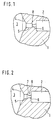
- FIG. 1 is the previous version of a valve piece 1 of a solenoid valve for controlling an injection valve shown.
- the bore 2 leads to the control pressure chamber of the Injector and stands over another throttle bore with the valve seat 4 of the relief chamber 3 of the Solenoid valve in fluid connection.
- the throttle bore is from the so-called A-choke 6 and the following Diffuser bore 5 formed, at the transition point an abrupt one between the cylindrical bores Cross-sectional change occurs.
- valve ball When the solenoid valve is energized, one does not lift shown valve ball in the relief chamber 3 from Valve seat 4, which causes the pressure in the valve chamber Towards the valve ball by using a pressure medium, mostly fuel under high pressure, from hole 2 over the throttle bore flows into the relief chamber 3. The this causes pressure drop in the bore 2 itself upstream control pressure chamber leads to that the valve needle of the injection valve opens and Fuel is injected under high pressure.
- a pressure medium mostly fuel under high pressure
- FIG. 2 shows an embodiment of the invention Solenoid valve in the area of the valve seat 4. Same parts from Figure 1 are in Figure 2 with the same reference numerals Mistake.
- a section 7 is involved continuously expanding cross section in the Throttle bore between the one leading to the control pressure chamber Bore 2 and the relief chamber 3 are provided.
- the exemplary embodiment is section 7 by a method for rounding the hole transition between A throttle 6 and diffuser bore 5 made.
- both the A throttle 6 and the diffuser bore 5 in comparison significantly shortened to the known embodiment according to FIG. 1.
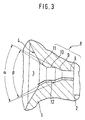
- FIG. 3 Another embodiment of the invention 3 shows the solenoid valve in the area of the valve seat 4.
- this embodiment follows the Control pressure chamber of injector leading bore 2 again the so-called A-choke 6 as cylindrical Bore with a significantly reduced cross section.
- a first conical section 9 follows according to the invention Opening angle ⁇ .
- the diffuser bore 10 is also in this embodiment of a conically widening cross section Section 11 followed, which opens into valve seat 4.
- the conical section 11 has an opening angle ⁇ .
- the opening angle ⁇ is too 50 °, the angle ⁇ selected to 60 °. Overall this will the opening angle of the flow channel successively expanded to then pass into the valve seat. By this measure can make the flow course extremely favorable to be influenced.
- the combination with the strong shortened diffuser bore 10 avoids too strong Pressure increases, the cavitation bubbles that may be present could implode.
- the complete contour of the Flow channel of the bore 8 is schematic in Fig. 3 shown and designated by reference numeral 12.
- the present invention is in any Bore cross-sections can be used, of course also more than two widening in cross section Sections within the bore 8 may be appropriate. In practice it has been shown that the one shown in FIG Is sufficient to prevent the occurrence of To prevent cavitation damage and thus the Functional reliability, in particular of common rail injectors to increase.
Landscapes
- Engineering & Computer Science (AREA)
- Chemical & Material Sciences (AREA)
- Combustion & Propulsion (AREA)
- Mechanical Engineering (AREA)
- General Engineering & Computer Science (AREA)
- Manufacturing & Machinery (AREA)
- Physics & Mathematics (AREA)
- Fluid Mechanics (AREA)
- Fuel-Injection Apparatus (AREA)
- Lift Valve (AREA)
- Details Of Valves (AREA)
- Magnetically Actuated Valves (AREA)
Applications Claiming Priority (2)
| Application Number | Priority Date | Filing Date | Title |
|---|---|---|---|
| DE10152173A DE10152173A1 (de) | 2001-10-23 | 2001-10-23 | Magnetventil zur Steuerung eines Einspritzventils |
| DE10152173 | 2001-10-23 |
Publications (2)
| Publication Number | Publication Date |
|---|---|
| EP1306545A2 true EP1306545A2 (fr) | 2003-05-02 |
| EP1306545A3 EP1306545A3 (fr) | 2005-04-06 |
Family
ID=7703365
Family Applications (1)
| Application Number | Title | Priority Date | Filing Date |
|---|---|---|---|
| EP02022596A Withdrawn EP1306545A3 (fr) | 2001-10-23 | 2002-10-09 | Soupape électromagnétique de commande d'une soupape d'injection |
Country Status (4)
| Country | Link |
|---|---|
| US (1) | US6834845B2 (fr) |
| EP (1) | EP1306545A3 (fr) |
| JP (1) | JP2003139018A (fr) |
| DE (1) | DE10152173A1 (fr) |
Cited By (2)
| Publication number | Priority date | Publication date | Assignee | Title |
|---|---|---|---|---|
| EP2292918A1 (fr) * | 2009-07-23 | 2011-03-09 | C.R.F. Società Consortile per Azioni | Injecteur de carburant doté d'une servocommande de mesure pour moteur à combustion interne |
| WO2013016745A1 (fr) * | 2011-07-29 | 2013-02-07 | Robert Bosch Gmbh | Orifices d'étranglement optimisés en termes de cavitation |
Families Citing this family (18)
| Publication number | Priority date | Publication date | Assignee | Title |
|---|---|---|---|---|
| US7832661B2 (en) * | 2003-09-29 | 2010-11-16 | Continental Automotive Systems Us, Inc. | Injector seat that includes a coined seal band with radius |
| WO2005033501A1 (fr) * | 2003-09-29 | 2005-04-14 | Siemens Vdo Automotive Corporation | Siege d'injecteur avec cordon de joint estampe |
| DE10355030A1 (de) * | 2003-11-25 | 2005-06-23 | Robert Bosch Gmbh | Ventil, insbesondere für eine Hochdruckpumpe einer Kraftstoffeinspritzeinrichtung für eine Brennkraftmaschine |
| JP4570149B2 (ja) * | 2005-04-05 | 2010-10-27 | 株式会社デンソー | 気体密度比検出装置、濃度検出装置及び燃料蒸気処理装置 |
| US20090255822A1 (en) * | 2006-06-21 | 2009-10-15 | Kazutaka Fujii | Electrical discharge surface treatment method and dressing method |
| DE102007004553A1 (de) * | 2007-01-30 | 2008-07-31 | Robert Bosch Gmbh | Kugelsitzventil mit verringertem Erosionsverhalten |
| US8333336B2 (en) * | 2007-03-06 | 2012-12-18 | Caterpillar Inc. | Cavitation erosion reduction strategy for valve member and fuel injector utilizing same |
| DE102008044096A1 (de) * | 2008-11-27 | 2010-06-02 | Robert Bosch Gmbh | Verfahren zur Herstellung von Drosselbohrungen mit niedrigem Kaviationsumschlagpunkt |
| DE102009045894A1 (de) | 2009-10-21 | 2011-04-28 | Robert Bosch Gmbh | Kraftstoffeinspritzsystem mit einem Ventil |
| JP5051279B2 (ja) * | 2009-12-21 | 2012-10-17 | 株式会社デンソー | 定残圧弁 |
| DE102010028844A1 (de) | 2010-05-11 | 2011-11-17 | Robert Bosch Gmbh | Schaltventil |
| JP5198511B2 (ja) * | 2010-06-29 | 2013-05-15 | 株式会社デンソー | 定残圧弁 |
| US9079281B2 (en) * | 2012-03-29 | 2015-07-14 | North American Fuel Systems Remanufacturing, LLC | Common rail valve seat refurbishing |
| DE102013214589A1 (de) * | 2013-07-25 | 2015-01-29 | Robert Bosch Gmbh | Schaltventil für einen Kraftstoffinjektor |
| DE102015204255A1 (de) | 2015-03-10 | 2016-09-15 | Robert Bosch Gmbh | Kraftstoffinjektor für ein Kraftstoffeinspritzsystem |
| US10180106B2 (en) | 2016-05-17 | 2019-01-15 | Hamilton Sundstrand Corporation | Solenoids for gas turbine engine bleed valves |
| CN107461271B (zh) * | 2017-09-12 | 2023-03-24 | 重庆潍柴发动机有限公司 | 气缸盖 |
| RU197666U1 (ru) * | 2020-01-27 | 2020-05-21 | Общество с ограниченной ответственностью Управляющая компания "Алтайский завод прецизионных изделий" | Топливная форсунка |
Citations (1)
| Publication number | Priority date | Publication date | Assignee | Title |
|---|---|---|---|---|
| DE19650865A1 (de) | 1996-12-07 | 1998-06-10 | Bosch Gmbh Robert | Magnetventil |
Family Cites Families (11)
| Publication number | Priority date | Publication date | Assignee | Title |
|---|---|---|---|---|
| US3804557A (en) * | 1972-05-26 | 1974-04-16 | A Bentley | Surface operated single tube pump |
| US4640304A (en) * | 1985-03-22 | 1987-02-03 | Baird Manufacturing Company | Overflow vent valve |
| US4946107A (en) * | 1988-11-29 | 1990-08-07 | Pacer Industries, Inc. | Electromagnetic fuel injection valve |
| DE19708104A1 (de) * | 1997-02-28 | 1998-09-03 | Bosch Gmbh Robert | Magnetventil |
| DE19710353A1 (de) * | 1997-03-13 | 1998-09-17 | Bosch Gmbh Robert | Magnetventil mit integriertem Rückschlagventil |
| DE19820341C2 (de) * | 1998-05-07 | 2000-04-06 | Daimler Chrysler Ag | Betätigungsvorrichtung für eine Hochdruck-Einspritzdüse für flüssige Einspritzmedien |
| DE19827267A1 (de) * | 1998-06-18 | 1999-12-23 | Bosch Gmbh Robert | Kraftstoff-Einspritzventil für Hochdruck-Einspritzung mit verbesserter Steuerung der Kraftstoffzufuhr |
| DE19859537A1 (de) * | 1998-12-22 | 2000-07-06 | Bosch Gmbh Robert | Kraftstoffeinspritzventil |
| DE19936667A1 (de) * | 1999-08-04 | 2001-02-22 | Bosch Gmbh Robert | Common-Rail-Injektor |
| DE19936943A1 (de) * | 1999-08-05 | 2001-02-08 | Bosch Gmbh Robert | Brennstoffeinspritzventil |
| DE10007175B9 (de) * | 2000-02-17 | 2004-11-04 | Siemens Ag | Einspritzventil für die Einspritzung von Kraftstoff in eine Verbrennungskraftmaschine |
-
2001
- 2001-10-23 DE DE10152173A patent/DE10152173A1/de not_active Withdrawn
-
2002
- 2002-10-09 EP EP02022596A patent/EP1306545A3/fr not_active Withdrawn
- 2002-10-22 US US10/278,596 patent/US6834845B2/en not_active Expired - Fee Related
- 2002-10-22 JP JP2002307233A patent/JP2003139018A/ja not_active Abandoned
Patent Citations (1)
| Publication number | Priority date | Publication date | Assignee | Title |
|---|---|---|---|---|
| DE19650865A1 (de) | 1996-12-07 | 1998-06-10 | Bosch Gmbh Robert | Magnetventil |
Cited By (2)
| Publication number | Priority date | Publication date | Assignee | Title |
|---|---|---|---|---|
| EP2292918A1 (fr) * | 2009-07-23 | 2011-03-09 | C.R.F. Società Consortile per Azioni | Injecteur de carburant doté d'une servocommande de mesure pour moteur à combustion interne |
| WO2013016745A1 (fr) * | 2011-07-29 | 2013-02-07 | Robert Bosch Gmbh | Orifices d'étranglement optimisés en termes de cavitation |
Also Published As
| Publication number | Publication date |
|---|---|
| EP1306545A3 (fr) | 2005-04-06 |
| US6834845B2 (en) | 2004-12-28 |
| JP2003139018A (ja) | 2003-05-14 |
| US20030087487A1 (en) | 2003-05-08 |
| DE10152173A1 (de) | 2003-04-30 |
Similar Documents
| Publication | Publication Date | Title |
|---|---|---|
| EP1306545A2 (fr) | Soupape électromagnétique de commande d'une soupape d'injection | |
| DE69636585T2 (de) | Kraftstoffeinspritzdüse | |
| DE3688753T2 (de) | Steuereinrichtung für elektro-hydraulisch betätigte Kraftstoffeinspritzventile. | |
| DE19612738C2 (de) | Speichereinspritzsystem für Brennkraftmaschinen | |
| DE4243665C2 (de) | Kraftstoffeinspritzeinrichtung, insbesondere Pumpedüse für Brennkraftmaschinen | |
| EP1123461B1 (fr) | Injecteur de structure compacte pour systeme d'injection a rampe commune de moteur a combustion interne | |
| DE10245151B4 (de) | Kraftstoffeinspritzvorrichtung | |
| EP0615064A1 (fr) | Système de commande d'une soupape d'injection d'un moteur à combustion interne | |
| WO2004092576A1 (fr) | Injecteur de carburant pour moteur a combustion interne | |
| EP3074623A1 (fr) | Injecteur de carburant | |
| DE19727074B4 (de) | Kraftstoffeinspritzventil für Zylindereinspritzung | |
| DE19726099A1 (de) | Kraftstoffeinspritzdüse | |
| DE102005000639A1 (de) | Druckmodulierte Common-Rail-Einspritzvorrichtung und Einspritzsystem | |
| EP3446006A1 (fr) | Soupape de fermeture et d'ouverture d'un système de conduites | |
| EP1599670B1 (fr) | Buse d'injection a trou borgne et a siege perfore destinee a un moteur a combustion interne et presentant un cone de transition entre le trou borgne et le siege d'aiguille de buse | |
| DE19843912B4 (de) | Kraftstoffeinspritzdüse | |
| EP1574701A1 (fr) | Injecteur de common rail | |
| DE10319535A1 (de) | Durchflussratensteuerungsmodul, Kraftstoffeinspritzvorrichtung mit derselben und Herstellungsverfahren des Durchflussratensteuerungsmoduls | |
| DE68913416T2 (de) | Hochdruck-Brennstoffeinspritzgerät für Motoren. | |
| EP4077908B1 (fr) | Buse d'injection pour l'injection de carburant sous haute pression | |
| DE102005023179B3 (de) | Einspritzventil mit einem erhöhten Druck im Ablaufraum | |
| DE102006000187A1 (de) | Fluideinspritzventil | |
| DE102019215119A1 (de) | Kraftstoffinjektor | |
| EP1176306A2 (fr) | Système d'injection de combustible pour moteurs à combustion interne | |
| DE10160490B4 (de) | Kraftstoff-Einspritzvorrichtung, Kraftstoffsystem sowie Brennkraftmaschine |
Legal Events
| Date | Code | Title | Description |
|---|---|---|---|
| PUAI | Public reference made under article 153(3) epc to a published international application that has entered the european phase |
Free format text: ORIGINAL CODE: 0009012 |
|
| AK | Designated contracting states |
Designated state(s): AT BE BG CH CY CZ DE DK EE ES FI FR GB GR IE IT LI LU MC NL PT SE SK TR |
|
| AX | Request for extension of the european patent |
Extension state: AL LT LV MK RO SI |
|
| PUAL | Search report despatched |
Free format text: ORIGINAL CODE: 0009013 |
|
| AK | Designated contracting states |
Kind code of ref document: A3 Designated state(s): AT BE BG CH CY CZ DE DK EE ES FI FR GB GR IE IT LI LU MC NL PT SE SK TR |
|
| AX | Request for extension of the european patent |
Extension state: AL LT LV MK RO SI |
|
| AKX | Designation fees paid | ||
| REG | Reference to a national code |
Ref country code: DE Ref legal event code: 8566 |
|
| STAA | Information on the status of an ep patent application or granted ep patent |
Free format text: STATUS: THE APPLICATION IS DEEMED TO BE WITHDRAWN |
|
| 18D | Application deemed to be withdrawn |
Effective date: 20051007 |