EP1306572A1 - Transmission pour véhicule automobile avec embrayage centralement fixé sur le vilebrequin - Google Patents
Transmission pour véhicule automobile avec embrayage centralement fixé sur le vilebrequin Download PDFInfo
- Publication number
- EP1306572A1 EP1306572A1 EP02017632A EP02017632A EP1306572A1 EP 1306572 A1 EP1306572 A1 EP 1306572A1 EP 02017632 A EP02017632 A EP 02017632A EP 02017632 A EP02017632 A EP 02017632A EP 1306572 A1 EP1306572 A1 EP 1306572A1
- Authority
- EP
- European Patent Office
- Prior art keywords
- drive train
- coupling
- arrangement
- central
- clutch
- Prior art date
- Legal status (The legal status is an assumption and is not a legal conclusion. Google has not performed a legal analysis and makes no representation as to the accuracy of the status listed.)
- Granted
Links
- 230000008878 coupling Effects 0.000 claims abstract description 155
- 238000010168 coupling process Methods 0.000 claims abstract description 155
- 238000005859 coupling reaction Methods 0.000 claims abstract description 155
- 230000005540 biological transmission Effects 0.000 claims abstract description 126
- 238000013016 damping Methods 0.000 claims description 16
- 230000005284 excitation Effects 0.000 claims description 12
- 239000002184 metal Substances 0.000 claims description 6
- 230000002093 peripheral effect Effects 0.000 claims description 5
- 230000015572 biosynthetic process Effects 0.000 claims description 4
- 230000000694 effects Effects 0.000 claims description 4
- 238000005755 formation reaction Methods 0.000 claims description 4
- 230000035939 shock Effects 0.000 claims description 2
- 230000010355 oscillation Effects 0.000 claims 1
- 238000009434 installation Methods 0.000 description 8
- 238000002485 combustion reaction Methods 0.000 description 6
- 238000013461 design Methods 0.000 description 6
- 239000007858 starting material Substances 0.000 description 5
- 230000004323 axial length Effects 0.000 description 4
- 210000002105 tongue Anatomy 0.000 description 4
- 230000000712 assembly Effects 0.000 description 3
- 238000000429 assembly Methods 0.000 description 3
- 238000011161 development Methods 0.000 description 3
- 230000018109 developmental process Effects 0.000 description 3
- 239000000463 material Substances 0.000 description 3
- 230000001404 mediated effect Effects 0.000 description 3
- 230000035515 penetration Effects 0.000 description 3
- 238000012549 training Methods 0.000 description 3
- 230000008901 benefit Effects 0.000 description 2
- 238000005520 cutting process Methods 0.000 description 2
- 230000010354 integration Effects 0.000 description 2
- 238000012423 maintenance Methods 0.000 description 2
- 238000004519 manufacturing process Methods 0.000 description 2
- 230000008439 repair process Effects 0.000 description 2
- 238000012546 transfer Methods 0.000 description 2
- 244000268528 Platanus occidentalis Species 0.000 description 1
- 229910000831 Steel Inorganic materials 0.000 description 1
- 238000010521 absorption reaction Methods 0.000 description 1
- 230000009471 action Effects 0.000 description 1
- 230000000903 blocking effect Effects 0.000 description 1
- 238000010276 construction Methods 0.000 description 1
- 230000000994 depressogenic effect Effects 0.000 description 1
- 238000006073 displacement reaction Methods 0.000 description 1
- 230000009977 dual effect Effects 0.000 description 1
- 230000002349 favourable effect Effects 0.000 description 1
- 238000007373 indentation Methods 0.000 description 1
- 238000009413 insulation Methods 0.000 description 1
- 239000012774 insulation material Substances 0.000 description 1
- 238000000034 method Methods 0.000 description 1
- 230000003534 oscillatory effect Effects 0.000 description 1
- 230000036316 preload Effects 0.000 description 1
- 238000003825 pressing Methods 0.000 description 1
- 230000002265 prevention Effects 0.000 description 1
- 230000008569 process Effects 0.000 description 1
- 239000010959 steel Substances 0.000 description 1
Images





Classifications
-
- F—MECHANICAL ENGINEERING; LIGHTING; HEATING; WEAPONS; BLASTING
- F16—ENGINEERING ELEMENTS AND UNITS; GENERAL MEASURES FOR PRODUCING AND MAINTAINING EFFECTIVE FUNCTIONING OF MACHINES OR INSTALLATIONS; THERMAL INSULATION IN GENERAL
- F16D—COUPLINGS FOR TRANSMITTING ROTATION; CLUTCHES; BRAKES
- F16D13/00—Friction clutches
- F16D13/58—Details
- F16D13/70—Pressure members, e.g. pressure plates, for clutch-plates or lamellae; Guiding arrangements for pressure members
- F16D13/71—Pressure members, e.g. pressure plates, for clutch-plates or lamellae; Guiding arrangements for pressure members in which the clutching pressure is produced by springs only
-
- F—MECHANICAL ENGINEERING; LIGHTING; HEATING; WEAPONS; BLASTING
- F16—ENGINEERING ELEMENTS AND UNITS; GENERAL MEASURES FOR PRODUCING AND MAINTAINING EFFECTIVE FUNCTIONING OF MACHINES OR INSTALLATIONS; THERMAL INSULATION IN GENERAL
- F16D—COUPLINGS FOR TRANSMITTING ROTATION; CLUTCHES; BRAKES
- F16D13/00—Friction clutches
- F16D13/58—Details
- F16D13/70—Pressure members, e.g. pressure plates, for clutch-plates or lamellae; Guiding arrangements for pressure members
-
- F—MECHANICAL ENGINEERING; LIGHTING; HEATING; WEAPONS; BLASTING
- F16—ENGINEERING ELEMENTS AND UNITS; GENERAL MEASURES FOR PRODUCING AND MAINTAINING EFFECTIVE FUNCTIONING OF MACHINES OR INSTALLATIONS; THERMAL INSULATION IN GENERAL
- F16D—COUPLINGS FOR TRANSMITTING ROTATION; CLUTCHES; BRAKES
- F16D21/00—Systems comprising a plurality of actuated clutches
- F16D21/02—Systems comprising a plurality of actuated clutches for interconnecting three or more shafts or other transmission members in different ways
- F16D21/06—Systems comprising a plurality of actuated clutches for interconnecting three or more shafts or other transmission members in different ways at least two driving shafts or two driven shafts being concentric
-
- F—MECHANICAL ENGINEERING; LIGHTING; HEATING; WEAPONS; BLASTING
- F16—ENGINEERING ELEMENTS AND UNITS; GENERAL MEASURES FOR PRODUCING AND MAINTAINING EFFECTIVE FUNCTIONING OF MACHINES OR INSTALLATIONS; THERMAL INSULATION IN GENERAL
- F16D—COUPLINGS FOR TRANSMITTING ROTATION; CLUTCHES; BRAKES
- F16D13/00—Friction clutches
- F16D13/58—Details
- F16D13/70—Pressure members, e.g. pressure plates, for clutch-plates or lamellae; Guiding arrangements for pressure members
- F16D2013/706—Pressure members, e.g. pressure plates, for clutch-plates or lamellae; Guiding arrangements for pressure members the axially movable pressure plate is supported by leaf springs
-
- F—MECHANICAL ENGINEERING; LIGHTING; HEATING; WEAPONS; BLASTING
- F16—ENGINEERING ELEMENTS AND UNITS; GENERAL MEASURES FOR PRODUCING AND MAINTAINING EFFECTIVE FUNCTIONING OF MACHINES OR INSTALLATIONS; THERMAL INSULATION IN GENERAL
- F16D—COUPLINGS FOR TRANSMITTING ROTATION; CLUTCHES; BRAKES
- F16D21/00—Systems comprising a plurality of actuated clutches
- F16D21/02—Systems comprising a plurality of actuated clutches for interconnecting three or more shafts or other transmission members in different ways
- F16D21/06—Systems comprising a plurality of actuated clutches for interconnecting three or more shafts or other transmission members in different ways at least two driving shafts or two driven shafts being concentric
- F16D2021/0607—Double clutch with torque input plate in-between the two clutches, i.e. having a central input plate
-
- F—MECHANICAL ENGINEERING; LIGHTING; HEATING; WEAPONS; BLASTING
- F16—ENGINEERING ELEMENTS AND UNITS; GENERAL MEASURES FOR PRODUCING AND MAINTAINING EFFECTIVE FUNCTIONING OF MACHINES OR INSTALLATIONS; THERMAL INSULATION IN GENERAL
- F16D—COUPLINGS FOR TRANSMITTING ROTATION; CLUTCHES; BRAKES
- F16D21/00—Systems comprising a plurality of actuated clutches
- F16D21/02—Systems comprising a plurality of actuated clutches for interconnecting three or more shafts or other transmission members in different ways
- F16D21/06—Systems comprising a plurality of actuated clutches for interconnecting three or more shafts or other transmission members in different ways at least two driving shafts or two driven shafts being concentric
- F16D2021/0684—Mechanically actuated clutches with two clutch plates
Definitions
- the invention relates to a motor vehicle drive train with one between a drive unit and a transmission arranged multiple coupling device, in particular double coupling device, for torque transmission between the drive unit and the transmission, wherein the clutch device is one of a first transmission input shaft assigned first clutch arrangement and one second clutch arrangement assigned to the second transmission input shaft comprises, wherein the transmission input shafts substantially coaxially an axis of rotation of the coupling device are arranged, one Input side of the coupling device via a torque transmission arrangement with a coupling end of an output shaft of the drive unit is directly or indirectly (directly or indirectly) coupled, and the Mornenten transmitting arrangement a radially outer connection area for connection to the coupling device and a radially inner connection area for direct or indirect connection at the coupling end having.
- the Torque transmission arrangement can be an integral, possibly one-part component a coupling module comprising the coupling device or can be a separate component compared to such a module or assembly, for example in the manner of a flex plate.
- the actual coupling device which may be as Unit is pre-assembled, and the flex plate independently mount, for example in such a way that first the flex plate on the output shaft is connected and then the coupling device on the flex plate is attached before then the drive unit with the transmission is connected, or in such a way that the flex plate is attached to the drive unit first and the coupling device is mounted on the transmission and then the drive unit and the transmission as well as the flex plate and the coupling device get connected.
- Coupling device assembly on the one hand and the flex plate generally the torque transmission arrangement
- the flex plate generally the torque transmission arrangement
- the torque transmission arrangement mediated at least one the radially inner connection area with the coupling end or a component or assembly attached to the coupling end in a rotationally fixed manner positively connecting, the radially inner connection area on Coupling or the component or assembly axially securing form-locking connecting element is non-rotatably connected, the positive connection element in a central radial area related to the axis of rotation is arranged, which is essentially one of the transmission input shafts occupied radial area corresponds to or smaller than This is.
- the positive connection element for example a Screw or a bolt, arranged in the central radial area is or - during assembly - to be arranged, becomes the possibility opened, the positive connection element from the axial direction in to assemble the central radial area.
- the positive connection element for example a Screw or a bolt
- the positive connection element becomes the possibility opened, the positive connection element from the axial direction in to assemble the central radial area.
- one Form-locking connecting element is this from the axial direction in the central Radial area accessible, for example if this is for maintenance or repair reasons, about to replace the coupling device or mentioned installation unit is required.
- the central radial area includes.
- each at least one as a friction disc have serving clutch disc, which with a respective coupling hub is non-rotatably arranged on the associated transmission input shaft, so it is preferred that in a state corresponding to an open one or not yet assembled drive train with a separately arranged Gearbox and separately arranged drive unit the positive connection element through a central channel on the drive unit arranged coupling device is accessible or mountable.
- This Central channel is defined by receiving openings of the coupling hubs for the respective assigned transmission input shaft and possibly by a Central passage through the transmission input shafts Opening of a unit connected to the coupling device Actuating module that actuates the clutch assemblies serves.
- a motor vehicle powertrain with one between one Drive unit and a gearbox arranged coupling device for Torque transmission between the drive unit and the at least a transmission having a transmission input shaft
- the coupling device at least one associated with a transmission input shaft
- Coupling arrangement comprises, wherein an input side of the coupling device via a moment transfer arrangement with a coupling end an output shaft of the drive unit directly or indirectly (immediately or indirectly) is coupled, and wherein the torque transmission arrangement a radially outer connection area for connection to the coupling device and a radially inner connection area for direct or indirect connection at the coupling end
- the Powertrain is characterized in that the torque transmission arrangement mediating at least one the radially inner connection area with the coupling end or one non-rotatable at the coupling end attached component or assembly, the radially inner connection area at the coupling end or the component or assembly axially s
- one taken up by the transmission input shaft Radial area include the central radial area.
- the at least has a clutch disc serving as a friction disc, which with a Coupling hub arranged on the assigned transmission input shaft in a rotationally fixed manner it is preferred that in a state corresponding to an open one or not yet assembled powertrain with separately arranged gear and separately arranged drive unit Form-locking connecting element through a central channel on the Drive unit arranged coupling device accessible or mountable which is defined by a receiving opening of the coupling hub for the assigned transmission input shaft and possibly by an axial one Passage through the transmission input shaft allows central opening an actuation module connected to the coupling device to form a structural unit for actuating the clutch arrangement.
- Exactly one centrally arranged interlocking connection element is preferred, for example, a centrally located screw is provided.
- the positive connection element is special easy to install in a radial area close to the axis of rotation from the axial direction or accessible from the axial direction.
- the at least one form-fitting connecting element even the rotary coupling connection between the radially inner connection area and the coupling end or one at Coupling rotatably attached component or assembly.
- the positive connection element indirectly a rotary coupling connection between the radial inner connection area and the coupling end or one at the coupling end manufactures or secures non-rotatably attached component or assembly, in that the positive connection connecting element is associated with rotational driving information or rotary driving areas in mutual rotary driving engagement holds or presses.
- rotational driving information be provided, the at least one Hirth toothing or at least comprise a SAE toothing (preferably free of play).
- rotational driving information is provided that are at least one tab-tab-receiving combination include. For example, at least one pin-pin receptacle combination or pen-pen receptacle combination.
- a positive connection especially a positive connection Central connection
- a frictional connection in particular frictional central connection
- the form-locking connection element can be assigned to each other Rotational driving areas in mutual frictional rotational driving intervention hold or press.
- the rotary driving areas can be from be formed essentially rotationally symmetrical contact surfaces or have essentially rotationally symmetrical contact surfaces. It will in particular thought that the contact surfaces of peripheral surfaces a cone-cone holder combination are formed, which are central, in particular is arranged essentially coaxially to the axis of rotation.
- Axial shock and vibration excitations can occur in motor vehicle clutches and wobble from the drive unit problems do.
- the torque transmission arrangement is axially elastic is compliant to allow axial tolerance compensation or / and the coupling device of axial impact or / and Decouple vibrational excitations, and that the torque transmission arrangement regarding tipping / wobbling movements of the coupling end relative to a plane of rotation of the coupling device orthogonal is carried out elastically to the coupling device of Decouple tilting and / or wobbling movements of the coupling end.
- Axial tolerance compensation can result in the undesired forced fit be avoided without requiring very tight tolerances with regard to the axial dimensions of the overall assembly and the axial dimensions defining dimensions of the axially adjacent drive unit or the axially adjacent gear in the drive train Need to become. Furthermore, in contrast to the rigid connection of the Coupling device via conventional flex plates on the output shaft avoided that all suggestions from the drive unit (axial or / and wobbling suggestions) to the coupling device essentially be forwarded as the proposed torque transmission arrangement ensures a corresponding decoupling.
- the Torque transmission arrangement such axial elasticity or / and - Concerning a tilting / tumbling movement of the coupling end relative to one axis of rotation orthogonal plane of the coupling device - such Elasticity has a resonance frequency of that of the torque transmission arrangement and the coupling device formed vibratable Systems relating to axial vibrations and / or tilting / wobble vibrations in the drive train below one of the idle speed corresponding vibration excitation frequency.
- the torque transmission arrangement has a radially central deformation region which axially resilient and is carried out regarding the tilting / wobbling movements of the radially inner and the radially outer connection area is designed to be elastically resilient to one another.
- the radially outer connection area is formed by a ring section that the radially inner connection area from a preferably plate-shaped central or hub section is formed, and that the deformation region at least one connecting the ring section to the central or hub section Connection section, preferably several the ring section with the Connecting sections connecting central or hub sections.
- the radially outer connection area is formed by a ring part that the radially inner connection area from a preferably plate-shaped central or hub part is formed, and that the deformation region at least one the ring part connecting part connecting to the central or hub part, preferably several connecting the ring part with the central or hub part Connecting parts, wherein the ring part, the at least one connecting part and the central or hub part made as separate parts and to form the torque transmission arrangement with each other are connected, preferably riveted together.
- the ring part and the central or hub part can be inexpensive as Sheet metal parts can be executed. It has proven to be cheap for the connecting parts highlighted if these are strip-shaped. A development it is proposed that the strip-shaped connecting parts over extend a circumferential angle range in the circumferential direction.
- the connecting parts can be designed inexpensively as leaf springs or sheet metal strips his.
- a technically advantageous and a favorable axial softness or softness in the direction of tilt is characterized by this from that the respective connecting part in a central area with the central or hub part and at its two end areas with the Ring part is connected.
- the connecting parts can differ in areas overlap axially.
- the Connecting parts starting from a / the respective, with the ring part connected end area in an intermediate area between this respective End area and one connected to the central or hub part Cross the end area or the middle area in pairs.
- the torque transmission arrangement can advantageously be provided with a damping element arrangement to vibrations or vibration excitations to dampen.
- a damping element arrangement to vibrations or vibration excitations to dampen.
- the damping element arrangement between the radial outer connection area and the radially inner connection area parallel to the deformation area in the torque transmission arrangement is included and between the radially outer connection area and the radially inner connection area relating to axial relative movements or / and tilting / tumbling relative movements has a dampening effect.
- a another, also advantageous possibility is that the damping element arrangement between the radially outer connection area and the Deformation area and / or between the deformation area and the radially inner connection area in the torque transmission arrangement is included and between the radially outer connection area and the deformation area and / or between the deformation area and the radially inner connection area relating to axial relative movements or / and tilting / tumbling relative movements has a dampening effect.
- the damping element arrangement can preferably be a plurality of Viscose-elastic, possibly strip-shaped damping elements.
- the invention further relates to a clutch system for an inventive Drive train, comprising a coupling device, if necessary Double or multiple clutch device, for torque transmission between the drive unit and the transmission, the coupling device at least one clutch arrangement assigned to a transmission input shaft comprises and an input side of the coupling device via a torque transmission arrangement with a coupling end Output shaft of the drive unit directly or indirectly coupled or connectable is.
- the torque transmission arrangement is according to the invention according to the torque transmission arrangement of the invention Drive train executed.
- the various aspects of the invention can be used for single clutches (with only one clutch arrangement) as well as double clutches (or generally multiple coupling devices; with two or several coupling arrangements) are carried out, both for couplings of the NORMALLY OPEN type as well as for couplings of the NORMALLY CLOSED type, and regardless of the type of actuation, namely both for clutches of the depressed actuation type as well as with couplings of the pulled type of actuation.
- At least some of the aspects and training opportunities of the invention can also be used in connection with wet-running single and double clutches (generally multiple clutches) of the multi-plate clutch type be of interest.
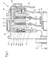
- Fig. 1 shows a double clutch 10 of the friction disc type, the first Clutch disc 12 of a first clutch assembly and a second Has clutch disc 14 of a second clutch arrangement.
- the first clutch disc 12 is designed with a hollow shaft first transmission input shaft 16 and the second clutch disc 14 is with a coaxially extending through the first transmission input shaft 16 second transmission input shaft 18 in a manner known per se in moment transmission connection.
- the clutch discs face For example, a coupling hub 20 or 22 on the relevant Transmission input shaft is pushed on and with this over driving information is rotatably coupled.
- the double clutch 10 has a housing arrangement 24 that a comprises first housing part 26 and a second housing part 28, which by Bolts 30 are interconnected.
- An annular section of the first clutch disk bearing friction linings on both sides 12 is axially between an abutment for the clutch disc forming pressure plate section 32 of the housing part 26 and one in the housing arrangement axially movable first pressure plate 34 arranged.
- the second clutch disc 14 is on both sides Friction-bearing ring area axially between which an abutment for the clutch plate forming pressure plate section 32 and one in the Housing arrangement axially movably held second pressure plate 36 held.
- the two pressure plates are each in a manner known per se and by tangential springs (tangential leaf springs) or the like held in the housing arrangement and each in the opening or disengaging direction spring biased.
- a first plate or diaphragm spring acts on the first pressure plate 34 40, the mediation of support rings 42, 44 and centering pin 46 a radially inwardly projecting ring section of the second housing part 28 is supported.
- Fig. 1 shows the first diaphragm spring in one unactuated condition. In this state, the diaphragm spring 40 cooperates their ring section 48 in the closing or engaging direction to the first Pressure plate 34 so that this against the first clutch disc 12 maximum contact pressure is applied, i.e. the clutch disc is maximal between the abutment of the pressure plate 32 and the pressure plate 34 is clamped. The first clutch assembly is thus fully engaged.
- the actuation tongues are for disengaging the first clutch arrangement or actuating lever 50 of the diaphragm spring 40 by applying corresponding axial forces at their end sections 52 in the direction to the drive unit, ie to the left in FIG. 1.
- the diaphragm spring then pivots between the support rings forming a pivot bearing 42 and 44, so that the axial forces acting on the pressure plate 34 be reduced and the pressure plate 34 under the action of their spring preload can move axially to the right or onto the clutch disc 34 acting clamping forces can be reduced.
- the second pressure plate 36 is a second diaphragm spring or plate spring 60 assigned, the ring portion 62 between support portions of the first housing part 28 and an annular one, a defined one Supporting radius 64 forming a support radius of a ring part Power transmission member 66 is clamped, which as a tie rod serving connecting bolt 68 connected to the second pressure plate 36 is.
- the second diaphragm spring presses 60 the force transmission element 64 in the direction of the transmission, that is to say in FIG. 1 to the right, causing the second pressure plate 36 against the second clutch disc 14 is pressed and the clutch disc accordingly between the second drive plate 36 and the pressure plate 32 axially is clamped.
- FIG. 1 shows in relation to the second clutch arrangement also the state of maximum indentation.
- To disengage the second Coupling arrangement are the operating tongues or operating levers 70 by applying corresponding axial forces to their end sections 72 in the direction of the drive unit, ie to the left in FIG. 1.
- the double clutch 10 is in the embodiment of FIG. 1 via a hereinafter referred to as flex plate arrangement 80 connected to a two-mass flywheel 82, which itself on the Output shaft 84 of a drive unit, in particular an internal combustion engine, is coupled.
- a two-mass flywheel or a simple one Flywheel may not be necessary, in particular because the pressure plate 32 and the pressure plates 34 and 36 themselves form a comparatively large turning mass, which as far as Inertia could serve.
- this rotating mass Double clutch a simple (rigid) flywheel or - if one Two-mass flywheel is desired - the secondary rotating mass of the Form two mass flywheels.
- the flex plate 80 shown in an axial view in FIG. 2 has an annular shape Outer part 90 and an inner plate, hub or ring part 92 on.
- the outer ring part 90 is connected to the first housing part 26 connected.
- the inner flex plate part 92 is over Connecting bolts 96 to the dual mass flywheel 82 or, if the two-mass flywheel is not used, with the output shaft 84, in particular crankshaft 84, connected.
- the radially outer flex plate part 90 and the radially inner flex plate part 92 are via elastic strip-shaped connecting elements 98 and 100, for example, connected via leaf springs 98 and 100, wherein between the outer flex plate part 90 and the respective connecting element 98 or 100 or / and between the inner flex plate part 92 and the respective connecting element 98 or 100 insulation material, for example, in the manner of a washer, can be arranged as 1 at 102 and 104.
- it can be viscoelastic Insulation elements arranged between the flex plate parts mentioned become.
- connection between the mentioned flex plate parts that is between the radially outer flex plate part 90 and the connecting elements 98, 100 and between the radially inner flex plate part 92 and the connecting elements 98, 100 can be produced by riveting.
- 106 and 108 denote corresponding rivet elements in FIG. 1.
- the outer flex plate part 90 and the inner flex plate part 92 can be advantageous (in particular inexpensive) as sheet metal parts.
- the Connecting elements 98, 100 can, for example, as thin steel strips or leaf springs.
- One can for the flex plate arrangement provide similar or analogous configurations as they already do for clutch discs (so-called "tumble-soft clutch discs") and regarding the connection of torque converters to a drive element were proposed.
- the flex plate arrangement 80 has a “targeted” axial and a tilt of the outer flex plate part 90 relative to the inner flex plate part 92 enabling elastic compliance or softness, which Axial and wobble movements of the crankshaft 84 from the double clutch 10 can be kept away. This is especially true for a double clutch of particular importance, as compared to a single clutch has a larger rotating mass.
- a conventional ("rigid") flex plate there is a risk that an internal combustion engine used as a drive unit is also in operation occurring excitations a natural frequency of the oscillatable system (Flex plate + coupling) with regard to axial vibrations and possibly with regard to Vibrations in the "tilting direction", that is, wobble vibrations.
- the vibratable System are so far out of tune that a vibration Decoupling with regard to axial vibration or axial vibrations (general axial excitations) and possibly with regard to wobble movements or the achieved "wobble" from the drive unit becomes.
- the system can already start at idling speed "supercritical operation” work.
- the advantageously provided damping elements, 1 to a certain extent “in series” to the others Elements of the flex plate arrangement are switched to do the rest axial vibrations and, if necessary, wobble vibrations of said vibratable System to avoid or at least significantly reduce. It is also a "parallel connection" of damping elements to the Connecting elements possible, as is shown in more detail in FIG. 4 is explained.
- the flex plate arrangement 80 is also very advantageous in that that the resulting axial compliance is a "forced fit" when fitting the coupling, especially the coupling and an associated actuation module comprising a unit Powertrain can be avoided.
- a double clutch The following can be noted regarding the type of friction disc.
- Out Safety reasons should at least one of the two Coupling arrangements carried out according to the NORMALLY OPEN principle be the coupling arrangement or the coupling arrangements should therefore be actively closed via an axial force introduced into the coupling become.
- the clutch module and the actuation module are connected to one another, preferably a comprising the clutch module and the actuation module Complete module for integration into the drive train either on the engine side or pre-assembled on the transmission side, in contrast to conventional ones Solutions in which the clutch module is usually arranged on the motor side and the actuation module is fixed on the transmission side and then after the gearbox has been installed on the engine become.
- pre-assembly of a Complete module requires that the axial length of the complete module in advance is defined, at least when there are no complex additional measures were made that allow an adjustment of the axial length.
- the axial space in the drive train, in particular the axial length of the bell housing, geometrically predetermined could due to manufacturing tolerances with a fitting installation Forced fit occur. This can be achieved through the flexible plate arrangement of the embodiment given axial compliance become.
- the 1 has with its pressure and pressure plates for example a weight of 13 to 14 kg. As already mentioned, could In normal driving, axial vibrations occur when a conventional one (too hard) flex plate connection would be chosen.
- connection of the coupling to the Output shaft to provide the decoupling already explained and preferably the detuning of the oscillatory system to one Excitation frequency from the engine (approximately the ignition pulse of the last cylinder) reach, such that the resonant frequency of the vibratable Systems (flex plate arrangement 80 + double coupling or pressure plate module 10) is below idle speed.
- Fig. 2 shows an embodiment of a torque transmission arrangement for coupling an input side of the double clutch to a Output shaft of the drive unit in more detail.
- Fig. 2 shows specifically a torque transmission arrangement, which in turn can be referred to as a flex plate arrangement 80, which corresponds to the example of FIG. 1 outer ring member 90, a central or hub member 92 and the outer ring member 90 and connecting elements connecting the inner central or hub part 92 98 and 100.
- the fasteners can with the riveted outer ring part 90 or the inner central or hub part 92 be, in the area of the riveting respectively axially effective damping elements (such as the viscoelastic elements mentioned) between the mentioned components can be arranged to axial vibrations to dampen.
- FIG. 120 denotes fastening openings for the connecting screws in FIG. 2 94.
- 122 in Fig. 2 denotes mounting openings for the connecting screws 96.
- the riveting of the connecting elements with the radially outer flex plate part 90 or the radially inner flex plate part 92 are also designated by 106 and 108 in FIG. 2.
- the connecting elements 98 and 100 are each strip-shaped and themselves executed predominantly along a radius and on both Double riveted ends to the outer flex plate part 90. In one In the middle area, the connecting elements 98 and 100 are each double with a radially projecting tab portion 124 of the radially inner Flex plate part riveted twice.
- the flex plate parts 90 and 92 can be carried out with offsets, as can be seen in Fig. 1.
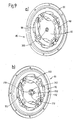
- FIG. 3 shows an embodiment variant in two perspective views 2.
- Ring part 90 could be called a flex plate, and the radially inner one on the Output shaft of the output unit or a flywheel attached or to be attached central or hub part 92, for example as a driver.
- the elastic connecting elements which are preferably designed as leaf springs 98 and 100 would then be the flex plate with the driver to understand connecting elements of the torque transmission arrangement one compared to the softness or elasticity of the flex plate 90 give significantly increased softness and elasticity.
- FIG. 4 shows a variant of the embodiment of FIG. 1.
- the only difference worth mentioning is that between the radial outer ring portion 90 and the radially inner central or hub portion 92 of the Flex plate arrangement 80 parallel to the connecting elements 98 and 100 effective damping elements 102 are effective, the damping elements not in series, but parallel to the connecting elements are switched.
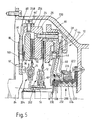
- Fig. 5 shows a further embodiment of a double clutch Type of friction disc including associated actuation module 200. It is again a multi-part flex plate assembly 80 with a radially outer Ring part 90 and a radially inner central or hub part 92 are provided, which in the present case is attached directly to the output shaft 84. On a two-mass flywheel is therefore dispensed with in the present exemplary embodiment. Instead, the clutch plates 12 and 14 are not in the direction of rotation essentially rigid, but as clutch discs with integrated Torsional vibration dampers 202 and 204 executed. The both flex plate parts 90 and 92 are in turn by elastic connecting elements 98 and 100 connected to each other already to achieve explained axial softness and tumbling softness.
- a radial screw connection is provided by connecting screws 94 'which between an axially extending collar portion 206 of the ring member 90 and the first housing part 26 act.
- the radial screw connection according to Fig. 5 enables a particularly simple assembly by at least one associated opening 208 in the transmission housing bell 210. Preferably several such openings 208 are to be provided distributed around the circumference, to limit further engine rotation during assembly or to avoid.
- the actuation module has a counter on the gear housing in particular a central sleeve 220 secured against twisting, which has an outer sleeve 222 and carries an inner sleeve 224.
- the outer sleeve 222 and the inner sleeve 224 are each with an external thread or internal thread with the Central sleeve 220 engages such that a rotation of the outer sleeve or / and the inner sleeve relative to the central sleeve an axial displacement of the relevant sleeve (outer sleeve or inner sleeve) induced.
- the outer sleeve 222 is provided with a release bearing 226, and the inner sleeve 224 is provided with a release bearing 228, through the mediation the outer sleeve or inner sleeve axial forces on the diaphragm spring tongues the diaphragm spring 40 or 60 can be exerted to the actuation tongues the respective diaphragm spring in the direction of the drive unit deflect and thus the first and / or second clutch assembly in To disengage direction.
- the sleeves for example, with radially projecting lever arms be executed, on which an respectively assigned actuator acts.
- the first diaphragm spring 40 holds in axial support relation.
- the second housing part 28 extends radially inwards up to a radial and axial bearing 230, which is located radially between the central sleeve 220 and an inner circumference of a ring portion 232 of the housing part 28 is held and axially by ring collars or retaining rings or the like is secured to the ring section 232 and the central sleeve 220.
- An important aspect of the embodiment or this embodiment underlying design idea is that due to of the closed axial force flow within the actual one Double clutch 10 and the actuation module 200 comprising overall module no axial forces in connection with the clutch actuation on the output shaft, in particular crankshaft 84, of the drive unit act that could put excessive strain on their bearings.
- the axial support is advantageous by a between the actual coupling device on the one hand and the associated actuating unit on the other hand effective central support bearing, in the example the bearing 230, mediated.
- the actuation module 200 is, as already indicated, before the integration the double clutch in the drive train with the actual double clutch 10 connected to one unit and can then be used as one unit pre-assembled on the transmission side in the bell housing, i.e. on the transmission side become.
- the flexible plate arrangement 80 is pre-assembled on Coupling end of the output shaft 84, in particular crankshaft 84 Mounting the gearbox on the engine then drive the clutch module and Flex plate arrangement 80 on top of each other and can then at least an opening 208 in the bell housing are interconnected.
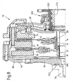
- Fig. 6 shows a further embodiment of a by means of a flex plate arrangement 80 connected to a crankshaft 84 double clutch 10 the type of friction disc.
- the one that is particularly well recognizable in FIG. 3 is implemented conventional connection, in which the driver or the central part 92 by means of several, preferably arranged on a pitch circle Screws 96 is screwed to the coupling end of the crankshaft 84.
- the Fastening of the screws would have to take place through several openings in the Coupling module take place if one of the double clutch 10 and the actuation module 200 and the flex plate arrangement 80 would like to assemble the entire module as a structural unit in the drive train. in the In the case of the arrangement shown in FIG.
- examples of torque transmission arrangements specifically flex plate arrangements, presented on the one hand the above-described axial and tumbling softness or Have elasticity, on the other hand positive or frictional in combination with a single fastener, specifically a single screw, on the output shaft of the drive unit (especially on the crankshaft of a Internal combustion engine) can be attached to a motor vehicle clutch (especially a double clutch) axially soft and without large To connect assembly effort to the output shaft. Basically comes it also considers the vehicle clutch on a single flywheel or two-mass flywheel by means of a corresponding inventive Torque transmission arrangement, possibly flex plate arrangement, to tie.
- An important aspect is the central arrangement one or possibly several fasteners coaxial or in close Proximity to the axis of rotation of the coupling, so that the (respective) fastening element through a the transmission input shaft or transmission input shafts receiving central channel of the coupling or the built-in assembly can be installed or is accessible.
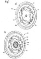
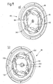
- the central part or the driver 92 according to FIG. 7 by means of of a single fastening element, here specifically by means of a single one Screw 300, attached to the output shaft
- the screw 300 Take-along information on the central part 92 and assigned counter-take-along information on the output shaft in mutual rotary driving engagement holds.
- the entrainment formations are, for example designed as Hirth serration 302. Comes into consideration for example, preferably a backlash-free SAE toothing.
- the Fastening screw 300 holds the central part 92 axially firmly on an end face of the coupling end of the crankshaft, so that the driving information preferably completely without rotational play in mutual rotary driving engagement being held.
- the double clutch 10 is by means of the flexible plate arrangement 80 connected to the crankshaft 84, according to the one used here Nomenclature a so-called "central connection" is realized, in which only a single additional fastener, namely screw 300, is used, which is arranged coaxially to the axis of rotation A and the driving information, here toothings 302, in mutual rotary driving engagement holds.
- the fastening screw 300 through a through the inner circumference of the Inner sleeve 224, the inner circumference of the coupling hub 20 of the first clutch disc 12 and the inner circumference of the coupling hub 22 of the second Clutch disc 14 defined central channel of the drive unit arranged, from the double clutch 10, the flex plate assembly 80 and the actuation module 200 unit formed from the axial direction accessible, for example, around this unit for maintenance or repair purposes disassemble from the drive unit.
- the unit on the drive unit through the fastening screw 300 screw this central channel into the coupling end of the crankshaft 84.
- a preassembled double clutch 10 is thus provided Built-in assembly that the flex plate assembly 80, the actual Double clutch 10 together with the clutch discs and that with the housing section 28 already connected actuation module 200.
- the built-in unit on the output shaft without major Assembly effort connected, especially screwed, using the access that is required Central channel.
- Such a pre-assembled built-in unit would need Gearboxes can no longer be axially fixed, so any axial Passport problems are avoided.
- an actuation module from Spindle drive construction for example of the module 200, should, however, for that axially fixed support part, d. H. the central sleeve 220 in the shown Embodiment, an anti-rotation in the circumferential direction relative to Gearbox can be provided.
- Fig. 10 shows the installation situation for the embodiment of Fig. 9.
- Die Double clutch 10 is mediated by the central screw 300 and pins engaging in a respective receptacle 314 of the output shaft 84 312 rotatably attached to the output shaft 84. It will be related achieved with Fig. 8 advantages.
- the central part or the Driver 92 a conical, possibly as a clamping cone or clamping cone identifiable section 320, which in the case of execution of the central part 92 is formed from sheet material from the sheet material can be.
- this conical section 320 engages in one corresponding conical hole or recess in the coupling end of the Output shaft or the flywheel.
- the appropriately dressed Central screw 300 are the conical outer peripheral surface of the Section 320 and a corresponding conical inner peripheral surface of the Hole (or generally the recess) in mutual frictional engagement Kept engaged.
- FIG. 12 shows an example of an installation situation for the flex plate arrangement 80 of FIG. 11. It can be seen how the conical projection or Section 320 of the central part 92 in an associated conical recess 322 of the crankshaft 84 engages, with a slightly different Inclination angle of the conical outer peripheral surface of the section 320 and the conical inner circumferential surface of the recess 322. This creates a strong jam with a correspondingly strong frictional connection reached between the named areas.
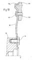
- Fig. 13 shows one in principle arbitrarily, for example, conventionally executed Flex plate 80, which by means of connecting elements, in particular Screws 96, is rotatably attached to the output shaft 84.
- the Screws 96 are on a radius at a clear distance from the axis of rotation A arranged so that no central connection in the sense of the nomenclature is realized in this application.
- the flex plate bears one radially outside from an extending in the axial direction Collar section 334 shaped starter ring gear 336.
- the starter ring gear can, for example, in the sheet material of the flex plate 80 be rolled up.
- a major advantage of the explained design of the flex plate is that one-piece and therefore inexpensive representation of the starter ring gear. In addition, problems are avoided that occur when attaching a separate manufactured ring gear could arise on a flex plate.
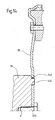
- FIG. 14 shows an embodiment variant of the flex plate of FIG. 13.
- Opposite 13 is the flex plate of FIG. 13 in the flex plate 80 of FIG Central connection of the flex plate according to the invention to the output shaft, in particular crankshaft 84.
- It is a central screw 300 provided, which is arranged coaxially to the axis of rotation and the flex plate axially fixed to the crankshaft 84 or the coupling end.
- the Dimensions of the pin projection 340 in the orthogonal to the axis of rotation A Plane and the dimensions of the opening 342 in that plane matched to one another in such a way that an essentially rotational play-free Rotational driving connection between the flex plate 80 and the crankshaft 84 is guaranteed.
Landscapes
- Engineering & Computer Science (AREA)
- General Engineering & Computer Science (AREA)
- Mechanical Engineering (AREA)
- Mechanical Operated Clutches (AREA)
- Hydraulic Clutches, Magnetic Clutches, Fluid Clutches, And Fluid Joints (AREA)
- Arrangement Of Transmissions (AREA)
- Hybrid Electric Vehicles (AREA)
- Dynamo-Electric Clutches, Dynamo-Electric Brakes (AREA)
Applications Claiming Priority (2)
| Application Number | Priority Date | Filing Date | Title |
|---|---|---|---|
| DE10149704 | 2001-10-09 | ||
| DE10149704A DE10149704A1 (de) | 2001-10-09 | 2001-10-09 | Eingangsseitig zentral an einer Drehwelle oder Drehkomponente angebundene Kupplungseinrichtung in einem Kraftfahrzeug-Antriebsstrang |
Publications (2)
| Publication Number | Publication Date |
|---|---|
| EP1306572A1 true EP1306572A1 (fr) | 2003-05-02 |
| EP1306572B1 EP1306572B1 (fr) | 2005-10-19 |
Family
ID=7701861
Family Applications (1)
| Application Number | Title | Priority Date | Filing Date |
|---|---|---|---|
| EP02017632A Expired - Lifetime EP1306572B1 (fr) | 2001-10-09 | 2002-08-06 | Transmission pour véhicule automobile avec embrayage centralement fixé sur le vilebrequin |
Country Status (4)
| Country | Link |
|---|---|
| US (1) | US6830140B2 (fr) |
| EP (1) | EP1306572B1 (fr) |
| AT (1) | ATE307302T1 (fr) |
| DE (2) | DE10149704A1 (fr) |
Cited By (3)
| Publication number | Priority date | Publication date | Assignee | Title |
|---|---|---|---|---|
| EP1862687A3 (fr) * | 2006-06-01 | 2010-09-29 | ZF Friedrichshafen AG | Agencement de transmission d'un couple de rotation pour ligne de transmission de véhicule |
| WO2013020531A1 (fr) * | 2011-08-05 | 2013-02-14 | Schaeffler Technologies AG & Co. KG | Groupe embrayage |
| WO2017137039A1 (fr) * | 2016-02-12 | 2017-08-17 | Schaeffler Technologies AG & Co. KG | Système d'embrayage comprenant un dispositif d'actionnement solidaire du couvercle et palier de support, situé dans l'embrayage, sous la forme d'un palier de couvercle |
Families Citing this family (32)
| Publication number | Priority date | Publication date | Assignee | Title |
|---|---|---|---|---|
| BR0205837B1 (pt) * | 2001-08-06 | 2013-03-05 | processo para a montagem de um sistema de embreagem. | |
| EP1298339B1 (fr) * | 2001-09-28 | 2004-03-10 | ZF Sachs AG | Arrangement d'accouplement multiple, notamment embrayage double |
| EP1384909B1 (fr) * | 2002-07-25 | 2012-02-15 | ZF Sachs AG | Ensemble à embrayage double |
| EP1391623A3 (fr) * | 2002-08-22 | 2004-09-29 | ZF Sachs AG | Embrayage double |
| EP1496288B1 (fr) | 2003-07-07 | 2007-01-10 | BorgWarner Inc. | Amortisseur de vibrations torsionelles |
| EP1496289B1 (fr) | 2003-07-07 | 2011-10-19 | BorgWarner, Inc. | Amortisseur de vibrations de torsion immergé dans un liquide |
| EP1496287B1 (fr) * | 2003-07-07 | 2006-11-29 | BorgWarner Inc. | Ligne de transmission |
| US20050252745A1 (en) * | 2004-05-14 | 2005-11-17 | Joseph Vanselous | Dual clutch assembly for a motor vehicle powertrain |
| US6997298B2 (en) * | 2004-05-14 | 2006-02-14 | Ford Global Technologies, Llc | Dual clutch assembly for a motor vehicle powertrain |
| US7063195B2 (en) * | 2004-07-27 | 2006-06-20 | Ford Global Technologies, Llc | Dual clutch assembly for a motor vehicle powertrain |
| US7293637B2 (en) * | 2005-01-06 | 2007-11-13 | Ford Global Technologies, Inc. | Modular twin clutch transmission input for hybrid vehicle |
| FR2886998B1 (fr) * | 2005-06-14 | 2007-08-24 | Valeo Embrayages | Mecanisme d'embrayages multiples avec butee a grands debattements |
| FR2886996B1 (fr) * | 2005-06-14 | 2007-08-17 | Valeo Embrayages | Mecanisme d'embrayages multiples avec disque de friction en 2 parties |
| US7100544B1 (en) | 2005-07-29 | 2006-09-05 | Borgwarner Inc. | Pneumatic cone clutch fan drive having threaded attachment method for drive shaft of clutch to hub mounting |
| DE102006056293A1 (de) * | 2005-12-22 | 2007-06-28 | Luk Lamellen Und Kupplungsbau Beteiligungs Kg | Mehrteilige Antriebsscheibe |
| FR2938029B1 (fr) * | 2008-11-06 | 2011-08-05 | Valeo Embrayages | Systeme d'accouplement comportant des moyens de liaison en rotation sans jeu reglables axialement entre un volant moteur et le plateau de reaction |
| US8697970B2 (en) * | 2009-01-12 | 2014-04-15 | Gavin Harrison | Cymbal mounting assembly |
| US8631920B2 (en) * | 2009-10-05 | 2014-01-21 | GM Global Technology Operations LLC | System and method for attaching a dual clutch to a flywheel |
| US8991166B2 (en) | 2010-12-01 | 2015-03-31 | Schaeffler Technologies Ag & Co Kg | Torque converter drive connection |
| DE102011001881A1 (de) * | 2011-04-07 | 2012-10-11 | Mühlhoff Umformtechnik GmbH | Verfahren zur Herstellung eines Schwungrads |
| DE102011084672B4 (de) | 2011-10-18 | 2022-01-13 | Schaeffler Technologies AG & Co. KG | Zentriereinrichtung für eine Kupplungsvorrichtung |
| KR101755714B1 (ko) * | 2011-11-11 | 2017-07-10 | 현대자동차주식회사 | 변속기의 샤프트 댐퍼 |
| DE102012214591B4 (de) | 2012-08-16 | 2015-08-20 | Ford Global Technologies, Llc | Doppelkupplung für ein Getriebe |
| DE102013215915A1 (de) | 2012-08-16 | 2014-05-15 | Ford Global Technologies, Llc | Doppelkupplungsgetriebe |
| DE102014221278B4 (de) | 2013-10-30 | 2025-06-18 | Schaeffler Technologies AG & Co. KG | Antriebsanordnung |
| US9415761B2 (en) | 2014-10-24 | 2016-08-16 | Ford Global Technologies, Llc | Methods and system for improving hybrid vehicle gear shifting |
| US20160252170A1 (en) * | 2014-12-09 | 2016-09-01 | Schaeffler Technologies AG & Co. KG | Torque converter drive connection |
| US9638605B2 (en) * | 2015-07-30 | 2017-05-02 | Toyota Motor Engineering & Manufacturing North America, Inc. | Adapter assemblies including engagement assemblies |
| GB201514150D0 (en) * | 2015-08-11 | 2015-09-23 | Raicam Clutch Ltd | Torsional vibration dampers |
| DE102018211374B4 (de) * | 2018-07-10 | 2025-09-11 | Zf Friedrichshafen Ag | Rotorträger für eine elektrische Maschine |
| DE202019101918U1 (de) * | 2019-03-08 | 2020-06-09 | Liebherr-Components Biberach Gmbh | Temperiervorrichtung für Antriebs- und/oder Getriebeeinheiten wie Tunnelbohrer-Getriebe |
| CN114905963A (zh) * | 2021-02-08 | 2022-08-16 | 舍弗勒技术股份两合公司 | 减振装置和混合动力装置 |
Citations (6)
| Publication number | Priority date | Publication date | Assignee | Title |
|---|---|---|---|---|
| DE689437C (de) * | 1936-02-16 | 1940-03-20 | Ewald Hering Dr Ing | Doppelkupplung, insbesondere fuer Zahnraederwechselgetriebe von Kraftfahrzeugen |
| FR1328670A (fr) * | 1962-07-10 | 1963-05-31 | Traktorenwerk Schonebeck Veb | Embrayage double, notamment pour tracteurs |
| US5279183A (en) * | 1990-04-26 | 1994-01-18 | Fichtel & Sachs Ag | Combination of a crankshaft and a flywheel |
| US5524739A (en) * | 1993-03-26 | 1996-06-11 | Fichtel & Sachs Ag | Transmission having a clutch with an arrangement for fastening the clutch to the crankshaft and a method of making same |
| US5799766A (en) * | 1995-05-22 | 1998-09-01 | Fichtel & Sachs Ag | Arrangement for the attachment of a flywheel to a crankshaft |
| US5901825A (en) * | 1996-07-10 | 1999-05-11 | Exedy Corporation | Modular clutch |
Family Cites Families (2)
| Publication number | Priority date | Publication date | Assignee | Title |
|---|---|---|---|---|
| DE4309871A1 (de) * | 1993-03-26 | 1994-09-29 | Fichtel & Sachs Ag | Anordnung zur Befestigung einer Kupplung an einer Kurbelwelle |
| JP3679901B2 (ja) * | 1997-07-08 | 2005-08-03 | 株式会社エクセディ | フライホイール組立体、及びトルクコンバータ |
-
2001
- 2001-10-09 DE DE10149704A patent/DE10149704A1/de not_active Withdrawn
-
2002
- 2002-08-06 AT AT02017632T patent/ATE307302T1/de not_active IP Right Cessation
- 2002-08-06 DE DE50204582T patent/DE50204582D1/de not_active Expired - Fee Related
- 2002-08-06 EP EP02017632A patent/EP1306572B1/fr not_active Expired - Lifetime
- 2002-10-07 US US10/265,939 patent/US6830140B2/en not_active Expired - Fee Related
Patent Citations (6)
| Publication number | Priority date | Publication date | Assignee | Title |
|---|---|---|---|---|
| DE689437C (de) * | 1936-02-16 | 1940-03-20 | Ewald Hering Dr Ing | Doppelkupplung, insbesondere fuer Zahnraederwechselgetriebe von Kraftfahrzeugen |
| FR1328670A (fr) * | 1962-07-10 | 1963-05-31 | Traktorenwerk Schonebeck Veb | Embrayage double, notamment pour tracteurs |
| US5279183A (en) * | 1990-04-26 | 1994-01-18 | Fichtel & Sachs Ag | Combination of a crankshaft and a flywheel |
| US5524739A (en) * | 1993-03-26 | 1996-06-11 | Fichtel & Sachs Ag | Transmission having a clutch with an arrangement for fastening the clutch to the crankshaft and a method of making same |
| US5799766A (en) * | 1995-05-22 | 1998-09-01 | Fichtel & Sachs Ag | Arrangement for the attachment of a flywheel to a crankshaft |
| US5901825A (en) * | 1996-07-10 | 1999-05-11 | Exedy Corporation | Modular clutch |
Non-Patent Citations (1)
| Title |
|---|
| SCHULZ-ANDRES H: "DER EINSATZ VON MODULKUPPLUNGEN IN ZUKUNFTIGEN PERSONENKRAFTWAGEN THE USE OF MODULAR CLUTCHES IN FUTURE PASSENGER CARS", MTZ MOTORTECHNISCHE ZEITSCHRIFT, FRANCKH'SCHE VERLAGSHANDLUNG,ABTEILUNG TECHNIK. STUTTGART, DE, vol. 55, no. 9, 1 September 1994 (1994-09-01), pages 488,490 - 491, XP000461873, ISSN: 0024-8525 * |
Cited By (6)
| Publication number | Priority date | Publication date | Assignee | Title |
|---|---|---|---|---|
| EP1862687A3 (fr) * | 2006-06-01 | 2010-09-29 | ZF Friedrichshafen AG | Agencement de transmission d'un couple de rotation pour ligne de transmission de véhicule |
| WO2013020531A1 (fr) * | 2011-08-05 | 2013-02-14 | Schaeffler Technologies AG & Co. KG | Groupe embrayage |
| CN103857936A (zh) * | 2011-08-05 | 2014-06-11 | 舍弗勒技术有限两合公司 | 离合设备 |
| CN103857936B (zh) * | 2011-08-05 | 2016-12-14 | 舍弗勒技术股份两合公司 | 离合设备 |
| WO2017137039A1 (fr) * | 2016-02-12 | 2017-08-17 | Schaeffler Technologies AG & Co. KG | Système d'embrayage comprenant un dispositif d'actionnement solidaire du couvercle et palier de support, situé dans l'embrayage, sous la forme d'un palier de couvercle |
| DE112017000805B4 (de) * | 2016-02-12 | 2025-05-08 | Schaeffler Technologies AG & Co. KG | Kupplungssystem mit deckelfester Betätigungsvorrichtung sowie in der Kupplung liegendem Stützlager in Form eines Deckellagers |
Also Published As
| Publication number | Publication date |
|---|---|
| DE10149704A1 (de) | 2003-04-10 |
| US20030066730A1 (en) | 2003-04-10 |
| DE50204582D1 (de) | 2006-03-02 |
| US6830140B2 (en) | 2004-12-14 |
| EP1306572B1 (fr) | 2005-10-19 |
| ATE307302T1 (de) | 2005-11-15 |
Similar Documents
| Publication | Publication Date | Title |
|---|---|---|
| EP1306572B1 (fr) | Transmission pour véhicule automobile avec embrayage centralement fixé sur le vilebrequin | |
| EP2109722B1 (fr) | Dispositif de transmission de couple | |
| DE102005037514B4 (de) | Drehmomentübertragungseinrichtung | |
| DE112008000154B4 (de) | Drehmomentübertragungseinrichtung | |
| DE112010004839B4 (de) | Drehmomentübertragungseinrichtung | |
| DE112011101227B4 (de) | Doppelkupplung | |
| WO2011137889A1 (fr) | Double embrayage | |
| DE102008012894A1 (de) | Betätigungseinrichtung für eine Reibungskupplungseinrichtung und von diesen gebildete Drehmomentübertragungseinrichtung | |
| DE19834729A1 (de) | Einrichtung zum Dämpfen von Drehschwingungen | |
| DE102011015270A1 (de) | Doppelkupplung | |
| WO2011116749A2 (fr) | Double embrayage | |
| EP1975437B1 (fr) | Dispositif de transmission de couple | |
| DE102009007829A1 (de) | Reibungskupplung für eine Drehmomentübertragungseinrichtung | |
| EP1226992B1 (fr) | Dispositif d'accouplement multiple adapté à être monté comme unité de montage préassemblée | |
| EP2347145B1 (fr) | Amortisseur de vibrations torsionnelles pour la chaîne cinématique d'un véhicule | |
| DE102008061588B4 (de) | Drehmomentübertragungseinrichtung mit blattfederartigen Elementen | |
| EP1413795B2 (fr) | Arrangement de transfert de couple | |
| EP3123043A2 (fr) | Double embrayage à disques multiples | |
| DE102010018193A1 (de) | Drehmomentübertragungseinrichtung | |
| EP1617096B1 (fr) | Dispositif de transmission de couple entre les composants dans une transmission d'un véhicule automobile | |
| EP1302687A2 (fr) | Dispositif à embrayages multiples | |
| DE10149700A1 (de) | Axial- und taumelelastische Anbindung einer Kupplungseinrichtung an einer Antriebseinheit in einem Kraftfahrzeug-Antriebsstrang | |
| DE102007031109A1 (de) | Antriebsstrang, insbesondere Antriebsstrang für ein Fahrzeug | |
| DE102009042823A1 (de) | Kupplung | |
| DE19634382B4 (de) | Zweimassen-Dämpfungsschwungrad, insbesondere für Kraftfahrzeuge, mit Momentbegrenzungsmitteln |
Legal Events
| Date | Code | Title | Description |
|---|---|---|---|
| PUAI | Public reference made under article 153(3) epc to a published international application that has entered the european phase |
Free format text: ORIGINAL CODE: 0009012 |
|
| 17P | Request for examination filed |
Effective date: 20030208 |
|
| AK | Designated contracting states |
Designated state(s): AT BE BG CH CY CZ DE DK EE ES FI FR GB GR IE IT LI LU MC NL PT SE SK TR |
|
| AX | Request for extension of the european patent |
Extension state: AL LT LV MK RO SI |
|
| 17Q | First examination report despatched |
Effective date: 20030316 |
|
| AKX | Designation fees paid |
Designated state(s): AT BE BG CH CY CZ DE DK EE ES FI FR GB GR IE IT LI LU MC NL PT SE SK TR |
|
| GRAP | Despatch of communication of intention to grant a patent |
Free format text: ORIGINAL CODE: EPIDOSNIGR1 |
|
| GRAS | Grant fee paid |
Free format text: ORIGINAL CODE: EPIDOSNIGR3 |
|
| GRAA | (expected) grant |
Free format text: ORIGINAL CODE: 0009210 |
|
| AK | Designated contracting states |
Kind code of ref document: B1 Designated state(s): AT BE BG CH CY CZ DE DK EE ES FI FR GB GR IE IT LI LU MC NL PT SE SK TR |
|
| PG25 | Lapsed in a contracting state [announced via postgrant information from national office to epo] |
Ref country code: IT Free format text: LAPSE BECAUSE OF FAILURE TO SUBMIT A TRANSLATION OF THE DESCRIPTION OR TO PAY THE FEE WITHIN THE PRESCRIBED TIME-LIMIT;WARNING: LAPSES OF ITALIAN PATENTS WITH EFFECTIVE DATE BEFORE 2007 MAY HAVE OCCURRED AT ANY TIME BEFORE 2007. THE CORRECT EFFECTIVE DATE MAY BE DIFFERENT FROM THE ONE RECORDED. Effective date: 20051019 Ref country code: CZ Free format text: LAPSE BECAUSE OF FAILURE TO SUBMIT A TRANSLATION OF THE DESCRIPTION OR TO PAY THE FEE WITHIN THE PRESCRIBED TIME-LIMIT Effective date: 20051019 Ref country code: FI Free format text: LAPSE BECAUSE OF FAILURE TO SUBMIT A TRANSLATION OF THE DESCRIPTION OR TO PAY THE FEE WITHIN THE PRESCRIBED TIME-LIMIT Effective date: 20051019 Ref country code: SK Free format text: LAPSE BECAUSE OF FAILURE TO SUBMIT A TRANSLATION OF THE DESCRIPTION OR TO PAY THE FEE WITHIN THE PRESCRIBED TIME-LIMIT Effective date: 20051019 Ref country code: NL Free format text: LAPSE BECAUSE OF FAILURE TO SUBMIT A TRANSLATION OF THE DESCRIPTION OR TO PAY THE FEE WITHIN THE PRESCRIBED TIME-LIMIT Effective date: 20051019 Ref country code: IE Free format text: LAPSE BECAUSE OF FAILURE TO SUBMIT A TRANSLATION OF THE DESCRIPTION OR TO PAY THE FEE WITHIN THE PRESCRIBED TIME-LIMIT Effective date: 20051019 |
|
| REG | Reference to a national code |
Ref country code: GB Ref legal event code: FG4D Free format text: NOT ENGLISH |
|
| REG | Reference to a national code |
Ref country code: CH Ref legal event code: EP |
|
| REG | Reference to a national code |
Ref country code: IE Ref legal event code: FG4D Free format text: LANGUAGE OF EP DOCUMENT: GERMAN |
|
| GBT | Gb: translation of ep patent filed (gb section 77(6)(a)/1977) |
Effective date: 20051201 |
|
| PG25 | Lapsed in a contracting state [announced via postgrant information from national office to epo] |
Ref country code: SE Free format text: LAPSE BECAUSE OF FAILURE TO SUBMIT A TRANSLATION OF THE DESCRIPTION OR TO PAY THE FEE WITHIN THE PRESCRIBED TIME-LIMIT Effective date: 20060119 Ref country code: DK Free format text: LAPSE BECAUSE OF FAILURE TO SUBMIT A TRANSLATION OF THE DESCRIPTION OR TO PAY THE FEE WITHIN THE PRESCRIBED TIME-LIMIT Effective date: 20060119 Ref country code: BG Free format text: LAPSE BECAUSE OF FAILURE TO SUBMIT A TRANSLATION OF THE DESCRIPTION OR TO PAY THE FEE WITHIN THE PRESCRIBED TIME-LIMIT Effective date: 20060119 Ref country code: GR Free format text: LAPSE BECAUSE OF FAILURE TO SUBMIT A TRANSLATION OF THE DESCRIPTION OR TO PAY THE FEE WITHIN THE PRESCRIBED TIME-LIMIT Effective date: 20060119 |
|
| PG25 | Lapsed in a contracting state [announced via postgrant information from national office to epo] |
Ref country code: ES Free format text: LAPSE BECAUSE OF FAILURE TO SUBMIT A TRANSLATION OF THE DESCRIPTION OR TO PAY THE FEE WITHIN THE PRESCRIBED TIME-LIMIT Effective date: 20060130 |
|
| REF | Corresponds to: |
Ref document number: 50204582 Country of ref document: DE Date of ref document: 20060302 Kind code of ref document: P |
|
| PG25 | Lapsed in a contracting state [announced via postgrant information from national office to epo] |
Ref country code: PT Free format text: LAPSE BECAUSE OF FAILURE TO SUBMIT A TRANSLATION OF THE DESCRIPTION OR TO PAY THE FEE WITHIN THE PRESCRIBED TIME-LIMIT Effective date: 20060320 |
|
| NLV1 | Nl: lapsed or annulled due to failure to fulfill the requirements of art. 29p and 29m of the patents act | ||
| REG | Reference to a national code |
Ref country code: IE Ref legal event code: FD4D |
|
| ET | Fr: translation filed | ||
| PLBE | No opposition filed within time limit |
Free format text: ORIGINAL CODE: 0009261 |
|
| STAA | Information on the status of an ep patent application or granted ep patent |
Free format text: STATUS: NO OPPOSITION FILED WITHIN TIME LIMIT |
|
| PG25 | Lapsed in a contracting state [announced via postgrant information from national office to epo] |
Ref country code: BE Free format text: LAPSE BECAUSE OF NON-PAYMENT OF DUE FEES Effective date: 20060831 Ref country code: LI Free format text: LAPSE BECAUSE OF NON-PAYMENT OF DUE FEES Effective date: 20060831 Ref country code: MC Free format text: LAPSE BECAUSE OF NON-PAYMENT OF DUE FEES Effective date: 20060831 Ref country code: CH Free format text: LAPSE BECAUSE OF NON-PAYMENT OF DUE FEES Effective date: 20060831 |
|
| 26N | No opposition filed |
Effective date: 20060720 |
|
| REG | Reference to a national code |
Ref country code: CH Ref legal event code: PL |
|
| PG25 | Lapsed in a contracting state [announced via postgrant information from national office to epo] |
Ref country code: AT Free format text: LAPSE BECAUSE OF NON-PAYMENT OF DUE FEES Effective date: 20060806 |
|
| BERE | Be: lapsed |
Owner name: ZF SACHS A.G. Effective date: 20060831 |
|
| PG25 | Lapsed in a contracting state [announced via postgrant information from national office to epo] |
Ref country code: EE Free format text: LAPSE BECAUSE OF FAILURE TO SUBMIT A TRANSLATION OF THE DESCRIPTION OR TO PAY THE FEE WITHIN THE PRESCRIBED TIME-LIMIT Effective date: 20051019 |
|
| PG25 | Lapsed in a contracting state [announced via postgrant information from national office to epo] |
Ref country code: LU Free format text: LAPSE BECAUSE OF NON-PAYMENT OF DUE FEES Effective date: 20060806 Ref country code: TR Free format text: LAPSE BECAUSE OF FAILURE TO SUBMIT A TRANSLATION OF THE DESCRIPTION OR TO PAY THE FEE WITHIN THE PRESCRIBED TIME-LIMIT Effective date: 20051019 |
|
| PGFP | Annual fee paid to national office [announced via postgrant information from national office to epo] |
Ref country code: DE Payment date: 20080821 Year of fee payment: 7 |
|
| PG25 | Lapsed in a contracting state [announced via postgrant information from national office to epo] |
Ref country code: CY Free format text: LAPSE BECAUSE OF FAILURE TO SUBMIT A TRANSLATION OF THE DESCRIPTION OR TO PAY THE FEE WITHIN THE PRESCRIBED TIME-LIMIT Effective date: 20051019 |
|
| PGFP | Annual fee paid to national office [announced via postgrant information from national office to epo] |
Ref country code: GB Payment date: 20080813 Year of fee payment: 7 |
|
| GBPC | Gb: european patent ceased through non-payment of renewal fee |
Effective date: 20090806 |
|
| PG25 | Lapsed in a contracting state [announced via postgrant information from national office to epo] |
Ref country code: DE Free format text: LAPSE BECAUSE OF NON-PAYMENT OF DUE FEES Effective date: 20100302 |
|
| PG25 | Lapsed in a contracting state [announced via postgrant information from national office to epo] |
Ref country code: GB Free format text: LAPSE BECAUSE OF NON-PAYMENT OF DUE FEES Effective date: 20090806 |
|
| PGFP | Annual fee paid to national office [announced via postgrant information from national office to epo] |
Ref country code: FR Payment date: 20100824 Year of fee payment: 9 |
|
| REG | Reference to a national code |
Ref country code: FR Ref legal event code: ST Effective date: 20120430 |
|
| PG25 | Lapsed in a contracting state [announced via postgrant information from national office to epo] |
Ref country code: FR Free format text: LAPSE BECAUSE OF NON-PAYMENT OF DUE FEES Effective date: 20110831 |