EP1306573A1 - Elastische buchse und methode zu druckseinbringen einer elastischen buchse - Google Patents
Elastische buchse und methode zu druckseinbringen einer elastischen buchse Download PDFInfo
- Publication number
- EP1306573A1 EP1306573A1 EP01947991A EP01947991A EP1306573A1 EP 1306573 A1 EP1306573 A1 EP 1306573A1 EP 01947991 A EP01947991 A EP 01947991A EP 01947991 A EP01947991 A EP 01947991A EP 1306573 A1 EP1306573 A1 EP 1306573A1
- Authority
- EP
- European Patent Office
- Prior art keywords
- support hole
- flange
- resilient
- diameter
- bush
- Prior art date
- Legal status (The legal status is an assumption and is not a legal conclusion. Google has not performed a legal analysis and makes no representation as to the accuracy of the status listed.)
- Granted
Links
Images


Classifications
-
- F—MECHANICAL ENGINEERING; LIGHTING; HEATING; WEAPONS; BLASTING
- F16—ENGINEERING ELEMENTS AND UNITS; GENERAL MEASURES FOR PRODUCING AND MAINTAINING EFFECTIVE FUNCTIONING OF MACHINES OR INSTALLATIONS; THERMAL INSULATION IN GENERAL
- F16F—SPRINGS; SHOCK-ABSORBERS; MEANS FOR DAMPING VIBRATION
- F16F1/00—Springs
- F16F1/36—Springs made of rubber or other material having high internal friction, e.g. thermoplastic elastomers
- F16F1/38—Springs made of rubber or other material having high internal friction, e.g. thermoplastic elastomers with a sleeve of elastic material between a rigid outer sleeve and a rigid inner sleeve or pin, i.e. bushing-type
- F16F1/3842—Method of assembly, production or treatment; Mounting thereof
-
- F—MECHANICAL ENGINEERING; LIGHTING; HEATING; WEAPONS; BLASTING
- F16—ENGINEERING ELEMENTS AND UNITS; GENERAL MEASURES FOR PRODUCING AND MAINTAINING EFFECTIVE FUNCTIONING OF MACHINES OR INSTALLATIONS; THERMAL INSULATION IN GENERAL
- F16F—SPRINGS; SHOCK-ABSORBERS; MEANS FOR DAMPING VIBRATION
- F16F1/00—Springs
- F16F1/36—Springs made of rubber or other material having high internal friction, e.g. thermoplastic elastomers
- F16F1/371—Springs made of rubber or other material having high internal friction, e.g. thermoplastic elastomers characterised by inserts or auxiliary extension or exterior elements, e.g. for rigidification
-
- F—MECHANICAL ENGINEERING; LIGHTING; HEATING; WEAPONS; BLASTING
- F16—ENGINEERING ELEMENTS AND UNITS; GENERAL MEASURES FOR PRODUCING AND MAINTAINING EFFECTIVE FUNCTIONING OF MACHINES OR INSTALLATIONS; THERMAL INSULATION IN GENERAL
- F16F—SPRINGS; SHOCK-ABSORBERS; MEANS FOR DAMPING VIBRATION
- F16F1/00—Springs
- F16F1/36—Springs made of rubber or other material having high internal friction, e.g. thermoplastic elastomers
- F16F1/38—Springs made of rubber or other material having high internal friction, e.g. thermoplastic elastomers with a sleeve of elastic material between a rigid outer sleeve and a rigid inner sleeve or pin, i.e. bushing-type
- F16F1/387—Springs made of rubber or other material having high internal friction, e.g. thermoplastic elastomers with a sleeve of elastic material between a rigid outer sleeve and a rigid inner sleeve or pin, i.e. bushing-type comprising means for modifying the rigidity in particular directions
Definitions
- the present invention relates to a resilient bush employed to, by fitting into a support hole formed in the article to be supported such as a suspension arm, resiliently support the article and to a method of pressure-insertion of this resilient bush into a support hole.
- a resilient bush that is used to support a suspension arm typically comprises an inner sleeve, a resilient body fixed to the circumference of this inner sleeve, and an outer sleeve fixed to the circumference of the resilient body; fixing is effected by pressure-insertion of the outer sleeve into a support hole formed in the suspension arm; however, with this bush, metallic members constituted by the suspension arm and outer sleeve are fitted together by insertion, so precise processing of the inside face of the support hole of the suspension arm is required, increasing processing costs, and making it necessary to use a high pressure-insertion load, which increases the equipment cost of the pressure-insertion device; in addition, the unit cost of the bush itself is raised by the provision of the outer sleeve, making it difficult to achieve reduction in costs.
- Resilient bushes are also conventionally known of the outer-sleeveless type, wherein the resilient body is made to directly contact the inside face of the support hole of the suspension arm, dispensing with the outer sleeve.
- the processing precision of the inside face of the support hole need only be rough and the pressure-insertion load can be low, so equipment costs are lowered and, in addition, the unit cost of the bush itself is lowered, making possible considerable cost savings.
- resilient bushes In both resilient bushes of the outer sleeveless type and the type fitted with an outer sleeve, resilient bushes are known, wherein an inserted sleeve is embedded in a diametrically intermediate region of the resilient body, in order to raise the spring constant of the resilient bush in the diametrical direction.
- resilient bushes of the outer sleeveless type referred to above have the advantage of enabling cost savings to be achieved as described above, they have the severe drawback that, since fixing to the article to be supported such as the suspension arm is obtained solely by the degree of tightening of the resilient body that can be achieved, the withdrawal load that they can withstand is greatly lowered compared with bushes of the type fitted with an outer sleeve, hence they cannot be employed in locations where they are subjected to load in the withdrawing direction or where they are subjected to complex inputs.
- the volume of the resilient body of the bush must be restricted, but, as a result, the initial compression ratio of the resilient body is limited so, even though an inserted sleeve is embedded in the resilient body, it is inferior in regard to spring balance performance in the diametrical direction, axial direction and torsional direction compared with a bush of the type fitted with an outer sleeve.
- an object of the present invention is to provide a resilient bush of the outer sleeveless type, wherein the withdrawal load is large and, furthermore, performance can also be improved.
- a resilient bush used to, by fitting into a support hole formed in an article to be supported, resiliently support the article comprises: an inner sleeve; a resilient body that directly contacts the inside face of the support hole and is fixed to the outer circumference of the inner sleeve; and a inserted sleeve embedded in a diametrically intermediate part of the resilient body, wherein flanges bent in the diametrically outwards direction are formed at both ends of the inserted sleeve, the flanges at both ends extending in the diametrically outwards direction from a projection plane in the axial direction of the support hole in a condition in which the resilient bush is fitted into the support hole; and a notch extending in a tubular portion of the inserted sleeve are formed in at least part, in the circumferential direction, of the flange at one end such that the flange at one end is capable of being reduced in diameter the flange at
- the resilient bush is pressure-inserted into the support hole of the article to be supported from the flange at one end of the inserted sleeve, in a condition with the flange at one end reduced in diameter.
- the flange at one end is expanded in diameter at the point where this flange is extracted from the support hole.
- resistance to withdrawal to one side or the other side in the axial direction of the resilient bush is obtained by means of the flange at one end and the flange at the other end, thereby providing a large withdrawal load.
- the contact with the inside face of the support hole is made by the resilient body, in contrast to pressure-insertion fitting of metal members as in the type fitted with an outer sleeve, the precision of processing of the inside face of the support hole can be rough, and the pressure-insertion load can also be small, making it possible to achieve pressure-insertion with pressure-insertion equipment of small size.
- the diametrical compression ratio of the resilient body in the initial condition thereof, in which the resilient bush is fitted into the support hole must be made large.
- the diameter of the one-end flange in the free condition of same prior to fitting the resilient bush into the support hole is made larger than the diameter when the resilient bush has been fitted into the support hole, compression of the resilient body in the diametrical direction in the initial condition can be achieved in particular, compression in the diametrical direction of the portion of the resilient body on the inside of the inserted sleeve can be achieved.
- a split groove reaching the end face of the leading end in said direction of insertion, is formed in the resilient body in the same phase as the notch, and this split groove and the notch are respectively formed in shapes expanding in width towards the leading end of the direction of insertion, the resilient body and the inserted sleeve can be reduced in diameter so as to become narrower towards the leading end in the direction of insertion, thereby facilitating pressure-insertion of the resilient bush in respect of the support hole.
- the flange at one end is preferably formed in elliptical shape with the short-diameter dimension being less than the hole diameter of the support hole and the notch being formed on both sides in the short-diameter direction of this flange.
- a projection is formed projecting in the diametrical direction in a portion of the outer circumferential surface of the resilient body on the opposite side to that of the leading end in the insertion direction, a force tending to diametrically expand the flange at one end by a lever action performed by the compressive force of the projection is generated, thereby reinforcing the withdrawal prevention function.
- the flanges when the resilient body is subjected to vulcanizing molding, the flanges must be subjected to grasp such that the inserted sleeve does not become offset in position.
- the location where the flanges are subjected to grasp cannot be covered by the resilient body, so resistance to corrosion is adversely affected.
- the portion where the location of application of grasp to the flange at one end coincides with the direction of diameter reduction, i.e. the portion that is most extended in the diametrically outwards direction from the projection plane of the support hole in the condition where the resilient bush is fitted into the support hole, the withdrawal prevention function is adversely affected by corrosion of this portion.
- the location where the flange at one end is subjected to grasp during vulcanizing molding of the resilient body should be set at a position offset in the circumferential direction from a portion coinciding with the direction of reduction of diameter of this flange at one end.
- the resilient body has a tubular portion that directly contacts the inside face of the support hole and is formed with leg portions fixed to the inner sleeve at the inner circumference of an intermediate portion in the axial direction of this tubular portion, and the inserted sleeve is embedded in this tubular portion and the notch is formed in the flange at one end of the inserted sleeve.
- a diametrical stopper portion is provided on one of the inner sleeve and the tubular portion of the resilient body that restricts reduction in diameter by abutting the other of the inner sleeve and the tubular portion of the resilient body when the flange at one end is reduced in diameter; alternatively, a split groove in the same phase as the notch and that reaches the end face at the leading end in the direction of insertion of the resilient bush in respect of the support hole is formed in the tubular portion of the resilient body, a wedge member being provided that fit into the split groove; if this is done, diameter reduction of the flange at the one end is restricted, so the withdrawal prevention function of this flange at one end is reinforced.
- a second object of the present invention is to provide a method whereby it is made possible to separate the diameter reduction guide after pressure-insertion and whereby smooth pressure-insertion of the resilient bush into the support hole can be achieved using the diameter reduction guide.
- an annular diameter reduction guide whose internal diameter decreases as the support hole is approached, is arranged at the aperture face on the inlet side of the support hole of the article to be supported, it being arranged to effect guidance into the support hole by reduction in diameter of the flange at one end of the inserted sleeve by pressing the flange into the diameter reduction guide, the diameter reduction guide being constituted by a plurality of segments that can be opened and closed in the diametrical direction, these segments being opened in the diametrical direction after pressure-insertion of the resilient bush; also, according to a second characteristic of the method of the present invention, an annular diameter reduction guide is arranged at the aperture face on the inlet side of the support hole of the article to be supported, and guide projections, the amount of whose projection diametrically inwards increases with approach to the support hole, are provided at a plurality of locations in the circumferential direction of the inner circumference of the diameter reduction guide, the
- the diameter reduction guide can be separated after pressure-insertion of the resilient bush without interfering with the flange at the other end of the inserted sleeve, and smooth pressure-insertion of the resilient bush into the support hole can thus be effected using the diameter reduction guide.
- the aperture face on the outlet side of the support hole of the article to be supported is contacted to a fixing jig so as to receive the pressure-insertion load of the resilient bush.
- a concavity is provided in the fixing jig to receive the flange at one end of the inserted sleeve when this is extruded from the outlet of the support hole on completion of pressure-insertion of the resilient bush, but, when the flange at the one end is extruded from the support hole, this flange is strongly pressed against the inside face of the concavity so as to attempt to effect expansion in the diametrical direction in the direction parallel with the width direction of the notch formed therein and may therefore catch on the fixing jig.
- a concavity is formed in elliptical shape whose long-diameter direction is a direction parallel with the width direction of the notch.
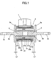
- numeral 1 denotes a suspension arm constituting an article to be supported; a resilient bush 2 is fitted into a support hole 1a at the end of suspension arm 1.
- the resilient bush 2 comprises a metal inner sleeve 20, a resilient body 21 made of rubber fixed to the circumference of the inner sleeve 20, and a inserted sleeve 22 made of metal embedded in a diametrically intermediate part of the resilient body 21; the resilient bush 2 is constituted in the form of the outer-sleeveless type with the resilient body 21 made to directly contact the inside face of the support hole 1a.
- a pair of support shafts 3, 3 are inserted into the inner sleeve 20 from both ends in the axial direction, such that flanges 3a, 3a at the base thereof contact both ends of the inner sleeve 20; a bracket 3b extending outwards from the flange 3a of each support shaft 3 is secured to a vehicle body (not shown) at a mounting hole 3c formed therein.
- the force directed in the rightwards direction is larger than the force directed in the leftwards direction in Figure 1; consequently, the clearance L1 between the flange 3a of the right-hand side support shaft 3 and the right-hand end of the resilient body 21 is made wider than the clearance L2 between the flange 3a of the left-hand side support shaft 3 and the left-hand end of the resilient body 21.
- the resilient body 21 comprises a tubular portion 21a that fits into the support hole 1a, leg portions 21b formed at a plurality of locations in the circumferential direction of the inner circumference of the central part of the tubular portions 21a and fixed to the inner sleeve 20, and stopper portions 21c, 21d that are formed by expansion in the diametrically outwards direction respectively at one end and the other end in the axial direction of the sleeve 21a, said one end and the other end projecting from support hole 1a in the axial direction; a inserted sleeve 22 is embedded in the sleeve 21a such that it reaches the stops 21c, 21d at both ends.
- flanges 22a, 22b that are bent in the diametrically outwards direction within the stops 21c, 21d respectively at the one end and the other end in the axial direction.
- the flange 22a at one end and the stopper portion 21c at one end are formed in elliptical shape with the short-diameter dimension of same is less than the hole diameter of the support hole 1a and, as shown in Figure 2(C), the flange 22b at the other end and the stop 21d at the other end are formed of practically circular shape.
- notches 22c, 22c extending in a tubular portion of the inserted sleeve 22 are formed positioned on one end flange 22a on both sides in the short-diameter direction of the elliptical shape; also, as shown in Figure 2(A) and Figure 3(A), in the sleeve 21a of resilient body 21, split grooves 21e, 21e are formed at the same phases as the notches 22c, 22c, reaching the end face of the one end stop 21c; furthermore, these notches 22c and split grooves 21e are formed in a shape of increasing width towards the one end in the axial direction, and the flange 22a and the stopper portion 21c at the one end are made to be capable of diameter reduction in the long diameter direction of the elliptical shape.
- the inserted sleeve 22 and the tubular portion 21a are divided into two halves of respectively halved shape by forming the notches 22c and the split grooves 21e over the entire length of the inserted sleeve 22 and the sleeve 21a, respectively, it would alternatively be possible to make the inserted sleeve 22 and the sleeve 21a respectively of non-divided construction by terminating the notches 22c and the split grooves 21e before flange 22b and the stop 21d at the other end.
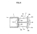
- the resilient bush 2 When the resilient bush 2 is fitted into the support hole 1a, the resilient bush 2 is pressure-inserted into the support hole 1a from one end thereof, with the flange 22a and the stop 21c at this one end being reduced in diameter as shown in Figure 4. In this way, the resilient bush 2 can be pressure-inserted under low load, and excellent pressure-insertion can be achieved without occurrence of catching or breakage etc at the stop 21c at the one end.
- the resilient bush 2 should be fitted into the support hole 1a such that the other-end flange 22b is positioned on the side where the larger of the forces in the axial direction that act on suspension arm 1 acts, i.e. the right-hand side in Figure 1 and Figure 5.
- the resilient body 21 in particular, the leg portions 21b on the inside of the inserted sleeve 22 can be compressed in the long-diameter direction in the initial condition in which no load acts on the suspension arm 1.
- the initial compression ratio of the resilient body 21 can be made large and, as a result, the spring constant of the resilient body 21 in the axial direction and torsional direction can be kept low while the initial compression ratio of the resilient body 21 is made large; performance is thereby improved.
- the location 22d where grasp is applied to the one-end flange 22a during vulcanizing molding of resilient body 21 is set in a position offset in the circumferential direction from the portion coinciding with the direction of diameter reduction (long-diameter direction) of this flange 22a, so that, even if corrosion occurs at grasping location 22d, the function of prevention of withdrawal by the one-end flange 22a is ensured.
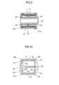
- Figure 6 shows a second embodiment of the resilient bush 2.
- this bush as shown in Figure 6(A), projections 21f that project in the diametrical direction are formed at a portion of the outer circumferential surface of the sleeve 21a of the resilient body 2, nearer to the other end, i.e. at a portion on the opposite side to the leading end in the direction of insertion of the resilient bush 2 into the support hole 1a.
- this embodiment is the same as the first embodiment.
- Figure 7 and Figure 8 show a third embodiment of the resilient bush 2.
- the difference between the third embodiment and the first embodiment described above is that rib-shaped diametrical stopper portions 23 project on the inner circumferential surface of the sleeve 21a of the resilient body 21 at the phase coinciding with the long-diameter direction, constituting the diameter reduction direction, of the one-end flange 22a of the inserted sleeve 22.
- reduction in diameter of the one-end flange 22a is suppressed by abutment of the diametrical stopper portions 23 with the inner sleeve 20, thereby reinforcing the withdrawal prevention function of the one-end flange 22a.
- Figure 9 shows a fourth embodiment of the resilient bush 2.
- an annular diametrical stopper portion 24 is provided at the outer circumference of the one end of the inner sleeve 20.
- the withdrawal prevention function of the one-end flange 22a is reinforced in the same way as in the third embodiment, by suppression of reduction in diameter of the one-end flange 22a of the inserted sleeve 22 by abutment of the one-end axial stopper portion 21c of the sleeve 21a with the diametrical stopper portion 24.
- this diametrical stopper portion 24 may be divided and provided on both sides in the long-diameter direction.
- Figure 10 shows a fifth embodiment of the resilient bush 2.
- wedge members 25 are provided that are fitted in from one end into the split grooves 21e of the sleeve 21a. Reduction in diameter of the one-end axial stop 21c of the sleeve 21a is thereby suppressed and concurrent reduction in diameter of the one-end flange 22a of the inserted sleeve 22 is also suppressed and the withdrawal prevention function of the one-end flange 22a is thereby reinforced in the same way as in the case of the third and fourth embodiments. Also, in the case of this fifth embodiment, there is also the advantage that the pressure-insertion load can be reduced, by pressure-inserting the resilient bush 2 into the support hole 1a in a condition with the wedge members 25 removed.
- the diameter reduction guide 5 is constituted by two segments 5a, 5a which can be freely opened and closed in the diametrical direction; the diameter reduction guide 5 is thereby separated after pressure-insertion of the resilient bush 2 has been effected, by opening these two segments 5a, 5a in the diametrical direction.
- the fixing jig 4 is provided with a concavity 4a for accepting the one-end flange 22a and the stop 21c extruded from the support hole 1a.
- the concavity 4a is formed in an elliptical shape whose long-diameter direction is the direction parallel with the width direction of the notches 22c, i.e. the long-diameter direction of the ellipse constituting the shape of the one-end flange 22a and the stop 21c. This thereby permits diametrical expansion within concavity 4a of the one-end flange 22a and the stop 21c extruded from the support hole 1a.
- the one-end flange 22a and the stop 21c are therefore not subjected to strong pressure contact with the inside face of the concavity 4a, so catching thereof on the fixing jig 4 is thereby prevented. It should be noted that the pressure-insertion load is securely received by abutment of the fixing jig 4 with the outlet side aperture face of the support hole 1a at the upper surface portion on both sides in the short-diameter direction of the concavity 4a.
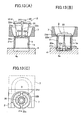
- the diameter reduction guide is not restricted to that described above and a diameter reduction guide 6 could be employed as shown in Figures 12(A), 12(B) and 12(C).
- This diameter reduction guide 6 is of annular shape and is provided with guide projections 6a, the amount of whose projection increases in the diametrically inwards direction as the support hole 1a is approached, at a plurality of locations in the circumferential direction of the inner circumference of diameter reduction guide 6, for example on both sides in the long-diameter direction of the one-end flange 22a and the stop 21c; the one-end flange 22a and the stop 21c are thus reduced in diameter by the guide projections 6a.
- recesses 22g are formed at a plurality of locations in the circumferential direction on the other-end flange 22b, in the same phase as the guide projections 6a. In this way, when the diameter reduction guide 6 is moved in the axial direction after pressure-insertion of the resilient bush 2, separation of the diameter reduction guide 6 from the resilient bush 2 in the axial direction can be achieved without creating interference with the other end flange 22b, by passing the guide projections 6a through the recesses 22g.
- a diameter reduction guide 7 could be employed as shown in Figure 13(A), 13(B), and 13(C).
- This diameter reduction guide 7 is formed with an internal diameter that decreases as the support hole 1a is approached and in this respect is the same as the diameter reduction guide 5 shown in Figure 11; however, in contrast to that shown in Figure 11, it is formed with a practically U-shaped opening on one side in the diametrical direction coinciding with the above-mentioned notch 22c, i.e. on one side in the short-diameter direction of the one-end flange 22a and the stop 21c.
- this diameter reduction guide 7 can be separated from the resilient bush 2 by moving the diameter reduction guide 7 in the opposite direction to the opening direction thereof, i.e. in the other of the short-diameter directions.
- the pressure-insertion operation is performed by bringing an aperture face on the outlet side of the support hole 1a of the article 1 to be supported into contact with the fixing jig 4 which is formed with the elliptical concavity 4a.
Landscapes
- Engineering & Computer Science (AREA)
- General Engineering & Computer Science (AREA)
- Mechanical Engineering (AREA)
- Manufacturing & Machinery (AREA)
- Springs (AREA)
- Vibration Prevention Devices (AREA)
- Vehicle Body Suspensions (AREA)
Applications Claiming Priority (7)
| Application Number | Priority Date | Filing Date | Title |
|---|---|---|---|
| JP2000236565A JP2002046031A (ja) | 2000-08-04 | 2000-08-04 | 弾性ブッシュの圧入方法 |
| JP2000236564 | 2000-08-04 | ||
| JP2000236563A JP3592213B2 (ja) | 2000-08-04 | 2000-08-04 | 弾性ブッシュ |
| JP2000236563 | 2000-08-04 | ||
| JP2000236564A JP3524475B2 (ja) | 2000-08-04 | 2000-08-04 | 弾性ブッシュ |
| JP2000236565 | 2000-08-04 | ||
| PCT/JP2001/006057 WO2002012748A1 (en) | 2000-08-04 | 2001-07-12 | Elastic bush and method of press-fitting elastic bush |
Publications (3)
| Publication Number | Publication Date |
|---|---|
| EP1306573A1 true EP1306573A1 (de) | 2003-05-02 |
| EP1306573A4 EP1306573A4 (de) | 2005-07-13 |
| EP1306573B1 EP1306573B1 (de) | 2007-12-19 |
Family
ID=27344257
Family Applications (1)
| Application Number | Title | Priority Date | Filing Date |
|---|---|---|---|
| EP01947991A Expired - Lifetime EP1306573B1 (de) | 2000-08-04 | 2001-07-12 | Elastische buchse und methode zu druckseinbringen einer elastischen buchse |
Country Status (12)
| Country | Link |
|---|---|
| US (1) | US6854723B2 (de) |
| EP (1) | EP1306573B1 (de) |
| KR (1) | KR100610547B1 (de) |
| CN (1) | CN1211595C (de) |
| AU (2) | AU6951101A (de) |
| BR (1) | BR0112916B1 (de) |
| CA (1) | CA2416641C (de) |
| DE (1) | DE60131978T2 (de) |
| MX (1) | MXPA03001020A (de) |
| MY (1) | MY128564A (de) |
| TW (1) | TW505750B (de) |
| WO (1) | WO2002012748A1 (de) |
Cited By (3)
| Publication number | Priority date | Publication date | Assignee | Title |
|---|---|---|---|---|
| DE102008033087B4 (de) * | 2008-07-15 | 2015-07-16 | Carl Freudenberg Kg | Dämpferlager |
| DE102022120686A1 (de) | 2022-08-16 | 2024-02-22 | Vibracoustic Se | Steglager zur Lagerung eines Fahrzeugteils |
| DE102005016593B4 (de) | 2004-04-29 | 2024-08-14 | DN Automotive Corp. | Lagerbuchsenaufbau |
Families Citing this family (46)
| Publication number | Priority date | Publication date | Assignee | Title |
|---|---|---|---|---|
| US20030025258A1 (en) * | 2001-08-02 | 2003-02-06 | Collyer Brent R. | Grooved or ribbed bushing and mating grooved or ribbed bushing receiving bore included within a suspension component |
| US20040108640A1 (en) * | 2002-12-09 | 2004-06-10 | Michael Robert Joseph | Elastomeric bearing assembly and associated pin structure |
| US7204479B2 (en) * | 2003-06-10 | 2007-04-17 | Cooper-Standard Automotive Inc. | Vibration isolator assembly having altered stress characteristics, and method of altering stress characteristics of same |
| DE202004010409U1 (de) * | 2004-07-02 | 2004-09-09 | Bomag Gmbh | Verbindungslager |
| DE102004034632A1 (de) * | 2004-07-16 | 2006-02-16 | Zf Friedrichshafen Ag | Elastomeres Buchsenlager mit Axialanschlag |
| JP4560376B2 (ja) * | 2004-10-29 | 2010-10-13 | 東海ゴム工業株式会社 | スタビライザブッシュ |
| US7451967B2 (en) * | 2005-02-24 | 2008-11-18 | The Pullman Company | Split outer tube anti-walkout bushing |
| DE102006031348A1 (de) * | 2006-07-06 | 2008-01-10 | Woco Avs Gmbh | Elastisches Einsatzlager |
| PL1892085T3 (pl) * | 2006-08-24 | 2013-05-31 | Rego Fix Ag | Prasa |
| WO2008043097A2 (en) | 2006-10-06 | 2008-04-10 | Lord Corporation | Vehicle with elastomeric bearing suspension system and elastomeric bearing therefor |
| EP2076688B1 (de) * | 2006-10-10 | 2012-01-25 | Trelleborg Automotive Germany GmbH | Verfahren zum kalibrieren einer elastomerfeder eines lagers |
| JP4382822B2 (ja) * | 2007-01-11 | 2009-12-16 | 本田技研工業株式会社 | 筒形防振装置 |
| DE102007016741B4 (de) * | 2007-04-07 | 2015-01-08 | Hübner GmbH | Elastomer-Metall-Element für ein Elastomer-Metall-Lager, insbesondere als Lagerverbindung zwischen einem Kuppelmodul und einem Fahrzeug |
| KR100953312B1 (ko) | 2008-06-10 | 2010-04-20 | 현대자동차주식회사 | 커플드 토션 빔 액슬타입 현가장치 |
| US8579510B2 (en) * | 2010-03-12 | 2013-11-12 | Hendrickson Usa, L.L.C. | Rotatable bar pin bushing assembly |
| WO2012024092A2 (en) * | 2010-08-16 | 2012-02-23 | Borgwarner Inc. | Bearing housing of an exhaust-gas turbocharger |
| CN102172905B (zh) * | 2011-02-11 | 2012-07-25 | 郑小玲 | 一种旋具嵌套筒 |
| CN102922443A (zh) * | 2011-08-12 | 2013-02-13 | 成都科盛石油科技有限公司 | 一种便于工件准确安装的定向连接套筒 |
| US8720920B2 (en) | 2012-08-29 | 2014-05-13 | Williams-Bayer Industries Inc. | Sleeve, sub-assembly, vehicular suspension assembly and methods for forming/assembling the same |
| DE102012221841B4 (de) * | 2012-11-29 | 2017-06-08 | Ford Global Technologies, Llc | Gummimetalllager für Kraftfahrzeug-Radaufhängung, Trapezlenker und Radaufhängung |
| CN103542029A (zh) * | 2013-09-30 | 2014-01-29 | 安徽华印机电股份有限公司 | 一种汽车用减震橡胶总成 |
| DE102013223295A1 (de) * | 2013-11-15 | 2015-05-21 | Bayerische Motoren Werke Aktiengesellschaft | Funktionelles Bauteil, insbesondere für ein Kraftfahrzeug, Verfahren zur Herstellung eines funktionellen Bauteils und Kraftfahrzeug, das ein funktionelles Bauteil umfasst |
| DE102014003324B4 (de) * | 2014-03-08 | 2015-11-26 | Audi Ag | Gummi-Metall-Hülsenlager |
| CN108138884A (zh) * | 2015-08-11 | 2018-06-08 | 亨德里克森美国有限责任公司 | 车辆悬架衬套组件及制造该衬套组件的方法 |
| US10603970B2 (en) * | 2015-12-15 | 2020-03-31 | Anand Nvh Products Inc. | Bushing for vehicle suspension system |
| CN106425926B (zh) * | 2016-10-20 | 2018-07-24 | 成都久欣时代科技有限公司 | 一种顶紧式导弹头工装夹具 |
| JP6831236B2 (ja) * | 2016-12-26 | 2021-02-17 | Toyo Tire株式会社 | 防振装置の製造方法 |
| CN106984958B (zh) * | 2017-04-25 | 2023-08-11 | 上海众源燃油分配器制造有限公司 | 一种用于管接头与法兰装配的装置 |
| WO2018207336A1 (ja) * | 2017-05-12 | 2018-11-15 | 住友理工株式会社 | 筒形防振装置 |
| CN107651151A (zh) * | 2017-08-16 | 2018-02-02 | 中国船舶重工集团公司第七〇九研究所 | 一种中间轴承自动对中装置 |
| KR102033154B1 (ko) * | 2018-04-30 | 2019-11-29 | 평화산업주식회사 | 전기자동차의 서스펜션 부쉬구조 |
| DE102018113503A1 (de) * | 2018-06-06 | 2019-12-12 | Vibracoustic Gmbh | Aggregatelager |
| CN109290809B (zh) * | 2018-11-28 | 2020-09-22 | 诺博橡胶制品有限公司 | 发动机悬置轴套总成组装装置 |
| CN109570943B (zh) * | 2018-12-07 | 2020-03-24 | 厦门凯立五金企业有限公司 | 一种用于开口环与座体组装的制具及装配方法 |
| JP7121860B2 (ja) * | 2019-10-29 | 2022-08-18 | 住友理工株式会社 | 車体ダンパーブレース |
| CN110948205A (zh) * | 2019-12-20 | 2020-04-03 | 无锡博金汽车部件有限公司 | 一种挡板与内衬套装配工艺 |
| CN113048038B (zh) * | 2019-12-26 | 2023-09-19 | 安徽美芝制冷设备有限公司 | 压缩机和制冷设备 |
| CN113048037B (zh) * | 2019-12-26 | 2024-01-05 | 安徽美芝制冷设备有限公司 | 压缩机和制冷设备 |
| CN111688226B (zh) * | 2020-06-08 | 2021-10-26 | 株洲时代新材料科技股份有限公司 | 非等厚橡胶球铰缩径装置及方法 |
| US20230406087A1 (en) * | 2020-10-14 | 2023-12-21 | Contitech Vibration Control Gmbh | Mount design with integrated tunable retention features |
| US12234876B2 (en) * | 2021-12-21 | 2025-02-25 | The Pullman Company | Optimized mass cast bar pin for bushing assembly |
| CN114810915B (zh) * | 2022-04-26 | 2023-06-23 | 博戈橡胶塑料(株洲)有限公司 | 一种液压衬套液体流动空间的密封方法 |
| CN115213665B (zh) * | 2022-07-07 | 2024-02-13 | 苏州通锦精密工业股份有限公司 | 导向臂卧式压装设备及其导向臂压装方法 |
| CN115795747B (zh) * | 2023-02-09 | 2023-06-09 | 中国航发四川燃气涡轮研究院 | 一种带挡边衬套的断裂预测方法 |
| CN116572686B (zh) * | 2023-05-30 | 2024-01-02 | 北京京安长信科技有限公司 | 一种重卡汽车可降低异响的易拆卸悬架衬套 |
| CN121552044A (zh) * | 2026-01-22 | 2026-02-24 | 镇江泛美汽车零部件有限公司 | 一种新能源电池包异形壳体零部件的衬套装配装置及方法 |
Family Cites Families (16)
| Publication number | Priority date | Publication date | Assignee | Title |
|---|---|---|---|---|
| JPS58102845U (ja) * | 1981-12-29 | 1983-07-13 | トヨタ自動車株式会社 | サスペンシヨンア−ムのブツシユ組立体 |
| JPS6122944U (ja) * | 1984-07-16 | 1986-02-10 | トヨタ自動車株式会社 | ブッシュ組立体 |
| US4644818A (en) | 1984-10-29 | 1987-02-24 | Tractech, Inc. | Differential apparatus with side-gear-centered center cam |
| JPS61109938U (de) * | 1984-12-22 | 1986-07-11 | ||
| JPS61205726A (ja) | 1985-03-11 | 1986-09-11 | Matsushita Electric Ind Co Ltd | 密閉式燃焼装置 |
| JPH0347794Y2 (de) * | 1985-06-12 | 1991-10-11 | ||
| JPS63198840A (ja) | 1987-02-13 | 1988-08-17 | Fumio Watanabe | 熱陰極電離真空計 |
| JPS63198840U (de) * | 1987-06-15 | 1988-12-21 | ||
| US5158271A (en) * | 1989-10-02 | 1992-10-27 | Gencorp. Inc. | Automotive powertrain mount |
| JP2582469B2 (ja) * | 1990-08-08 | 1997-02-19 | 日産自動車株式会社 | サスペンションメンバのマウンティング構造 |
| DE4305808C2 (de) * | 1993-02-25 | 1995-05-11 | Freudenberg Carl Fa | Hydraulisch dämpfende Hülsengummifeder |
| JPH0741091A (ja) | 1993-07-30 | 1995-02-10 | Toshiba Mach Co Ltd | 飲料冷却注出装置 |
| JPH08219210A (ja) * | 1995-02-13 | 1996-08-27 | Tokai Rubber Ind Ltd | 防振支持体 |
| DE19634215C2 (de) * | 1996-08-24 | 2000-11-09 | Porsche Ag | Zentrallager für eine Hinterachse eines Kraftfahrzeuges |
| DE19709669C1 (de) * | 1997-03-11 | 1998-06-18 | Mannesmann Boge Gmbh | Gummilager, insbesondere für die Lagerung eines Stabilisatorstabes an einem Kraftfahrzeug |
| JP2000110877A (ja) | 1998-10-01 | 2000-04-18 | Toyo Tire & Rubber Co Ltd | 弾性ブッシュ |
-
2001
- 2001-07-12 AU AU6951101A patent/AU6951101A/xx active Pending
- 2001-07-12 MX MXPA03001020A patent/MXPA03001020A/es active IP Right Grant
- 2001-07-12 AU AU2001269511A patent/AU2001269511B2/en not_active Ceased
- 2001-07-12 BR BRPI0112916-3A patent/BR0112916B1/pt not_active IP Right Cessation
- 2001-07-12 US US10/332,981 patent/US6854723B2/en not_active Expired - Fee Related
- 2001-07-12 CN CNB018131999A patent/CN1211595C/zh not_active Expired - Fee Related
- 2001-07-12 CA CA002416641A patent/CA2416641C/en not_active Expired - Fee Related
- 2001-07-12 WO PCT/JP2001/006057 patent/WO2002012748A1/ja not_active Ceased
- 2001-07-12 KR KR1020037000662A patent/KR100610547B1/ko not_active Expired - Fee Related
- 2001-07-12 DE DE60131978T patent/DE60131978T2/de not_active Expired - Lifetime
- 2001-07-12 EP EP01947991A patent/EP1306573B1/de not_active Expired - Lifetime
- 2001-07-27 TW TW090118442A patent/TW505750B/zh not_active IP Right Cessation
- 2001-08-02 MY MYPI20013644A patent/MY128564A/en unknown
Cited By (4)
| Publication number | Priority date | Publication date | Assignee | Title |
|---|---|---|---|---|
| DE102005016593B4 (de) | 2004-04-29 | 2024-08-14 | DN Automotive Corp. | Lagerbuchsenaufbau |
| DE102008033087B4 (de) * | 2008-07-15 | 2015-07-16 | Carl Freudenberg Kg | Dämpferlager |
| DE102022120686A1 (de) | 2022-08-16 | 2024-02-22 | Vibracoustic Se | Steglager zur Lagerung eines Fahrzeugteils |
| DE102022120686B4 (de) | 2022-08-16 | 2024-07-18 | Vibracoustic Se | Steglager zur Lagerung eines Fahrzeugteils |
Also Published As
| Publication number | Publication date |
|---|---|
| US20030111780A1 (en) | 2003-06-19 |
| BR0112916B1 (pt) | 2010-11-30 |
| TW505750B (en) | 2002-10-11 |
| BR0112916A (pt) | 2003-07-08 |
| CA2416641A1 (en) | 2003-01-16 |
| AU2001269511B2 (en) | 2005-03-10 |
| AU6951101A (en) | 2002-02-18 |
| CN1211595C (zh) | 2005-07-20 |
| US6854723B2 (en) | 2005-02-15 |
| EP1306573A4 (de) | 2005-07-13 |
| DE60131978D1 (de) | 2008-01-31 |
| KR100610547B1 (ko) | 2006-08-09 |
| MY128564A (en) | 2007-02-28 |
| MXPA03001020A (es) | 2003-09-22 |
| CN1443287A (zh) | 2003-09-17 |
| EP1306573B1 (de) | 2007-12-19 |
| WO2002012748A1 (en) | 2002-02-14 |
| CA2416641C (en) | 2007-11-27 |
| KR20030040362A (ko) | 2003-05-22 |
| DE60131978T2 (de) | 2008-12-04 |
Similar Documents
| Publication | Publication Date | Title |
|---|---|---|
| CA2416641C (en) | Resilient bush and method of pressure-insertion of a resilient bush | |
| US7887012B2 (en) | Insert for tube retaining bracket | |
| CN108779884B (zh) | 用于成型夹具的预定位器及具有这种预定位器的连接装置 | |
| CN104718406A (zh) | 夹具装置 | |
| US10920844B2 (en) | Vehicle suspension bushing assemblies and methods for manufacturing such bushing assemblies | |
| WO2015045750A1 (ja) | 筒型防振装置 | |
| US7568567B2 (en) | Snap-ring with additional loop | |
| CA2268326A1 (en) | Expanding lock control cable end fitting | |
| US20110175269A1 (en) | Stabilizer bush | |
| KR102329111B1 (ko) | 조립형 다이나믹 댐퍼 | |
| US20100130075A1 (en) | Female Electrical Contact Comprising Spring Contact Plates | |
| CA2155771C (en) | Tolerance compensating reusable clamp structure | |
| KR101705169B1 (ko) | 부시형 마운트 | |
| JP2002046031A (ja) | 弾性ブッシュの圧入方法 | |
| ZA200300931B (en) | Resilient bush and method of pressure-insertion of a resilient bush. | |
| JP3927690B2 (ja) | ブーツバンド | |
| CN210650538U (zh) | 一种孔用卡簧安装工具 | |
| US20240149662A1 (en) | Fixing device for connecting a first component to a second component and method for making a fixing device | |
| JP2023517577A5 (de) | ||
| KR20250014994A (ko) | 건설공사 자재용 커플러 | |
| JP3838126B2 (ja) | ストッパ付き防振ブッシュの製造方法 | |
| JP2009079722A (ja) | 筒型防振装置 | |
| KR20180067398A (ko) | 호스 클램프 및 호스 클램프용 텐션 스프링의 구조 | |
| JP4158221B2 (ja) | 部材の連結構造及び連結方法 | |
| JP2025127002A (ja) | ブッシュ |
Legal Events
| Date | Code | Title | Description |
|---|---|---|---|
| PUAI | Public reference made under article 153(3) epc to a published international application that has entered the european phase |
Free format text: ORIGINAL CODE: 0009012 |
|
| 17P | Request for examination filed |
Effective date: 20030204 |
|
| AK | Designated contracting states |
Designated state(s): AT BE CH CY DE DK ES FI FR GB GR IE IT LI LU MC NL PT SE TR |
|
| RBV | Designated contracting states (corrected) |
Designated state(s): BE DE ES FR GB TR |
|
| A4 | Supplementary search report drawn up and despatched |
Effective date: 20050530 |
|
| RIC1 | Information provided on ipc code assigned before grant |
Ipc: 7B 23P 19/02 B Ipc: 7F 16F 1/371 A Ipc: 7F 16F 15/08 B Ipc: 7F 16F 1/38 B |
|
| GRAP | Despatch of communication of intention to grant a patent |
Free format text: ORIGINAL CODE: EPIDOSNIGR1 |
|
| GRAS | Grant fee paid |
Free format text: ORIGINAL CODE: EPIDOSNIGR3 |
|
| GRAA | (expected) grant |
Free format text: ORIGINAL CODE: 0009210 |
|
| AK | Designated contracting states |
Kind code of ref document: B1 Designated state(s): BE DE ES FR GB TR |
|
| REG | Reference to a national code |
Ref country code: GB Ref legal event code: FG4D |
|
| REF | Corresponds to: |
Ref document number: 60131978 Country of ref document: DE Date of ref document: 20080131 Kind code of ref document: P |
|
| PG25 | Lapsed in a contracting state [announced via postgrant information from national office to epo] |
Ref country code: ES Free format text: LAPSE BECAUSE OF FAILURE TO SUBMIT A TRANSLATION OF THE DESCRIPTION OR TO PAY THE FEE WITHIN THE PRESCRIBED TIME-LIMIT Effective date: 20080330 |
|
| ET | Fr: translation filed | ||
| PG25 | Lapsed in a contracting state [announced via postgrant information from national office to epo] |
Ref country code: BE Free format text: LAPSE BECAUSE OF FAILURE TO SUBMIT A TRANSLATION OF THE DESCRIPTION OR TO PAY THE FEE WITHIN THE PRESCRIBED TIME-LIMIT Effective date: 20071219 |
|
| PGFP | Annual fee paid to national office [announced via postgrant information from national office to epo] |
Ref country code: TR Payment date: 20080618 Year of fee payment: 8 |
|
| PLBE | No opposition filed within time limit |
Free format text: ORIGINAL CODE: 0009261 |
|
| STAA | Information on the status of an ep patent application or granted ep patent |
Free format text: STATUS: NO OPPOSITION FILED WITHIN TIME LIMIT |
|
| 26N | No opposition filed |
Effective date: 20080922 |
|
| PGFP | Annual fee paid to national office [announced via postgrant information from national office to epo] |
Ref country code: GB Payment date: 20080716 Year of fee payment: 8 |
|
| PGFP | Annual fee paid to national office [announced via postgrant information from national office to epo] |
Ref country code: FR Payment date: 20090710 Year of fee payment: 9 |
|
| GBPC | Gb: european patent ceased through non-payment of renewal fee |
Effective date: 20090712 |
|
| PG25 | Lapsed in a contracting state [announced via postgrant information from national office to epo] |
Ref country code: GB Free format text: LAPSE BECAUSE OF NON-PAYMENT OF DUE FEES Effective date: 20090712 |
|
| REG | Reference to a national code |
Ref country code: FR Ref legal event code: ST Effective date: 20110331 |
|
| PG25 | Lapsed in a contracting state [announced via postgrant information from national office to epo] |
Ref country code: FR Free format text: LAPSE BECAUSE OF NON-PAYMENT OF DUE FEES Effective date: 20100802 |
|
| PG25 | Lapsed in a contracting state [announced via postgrant information from national office to epo] |
Ref country code: TR Free format text: LAPSE BECAUSE OF NON-PAYMENT OF DUE FEES Effective date: 20090712 |
|
| REG | Reference to a national code |
Ref country code: DE Ref legal event code: R084 Ref document number: 60131978 Country of ref document: DE Effective date: 20130513 |
|
| PGFP | Annual fee paid to national office [announced via postgrant information from national office to epo] |
Ref country code: DE Payment date: 20130711 Year of fee payment: 13 |
|
| REG | Reference to a national code |
Ref country code: DE Ref legal event code: R119 Ref document number: 60131978 Country of ref document: DE |
|
| PG25 | Lapsed in a contracting state [announced via postgrant information from national office to epo] |
Ref country code: DE Free format text: LAPSE BECAUSE OF NON-PAYMENT OF DUE FEES Effective date: 20150203 |
|
| REG | Reference to a national code |
Ref country code: DE Ref legal event code: R119 Ref document number: 60131978 Country of ref document: DE Effective date: 20150203 |