EP1306586A2 - Metalldichtung mit einer partiellen Oberflächenbeschichtung - Google Patents
Metalldichtung mit einer partiellen Oberflächenbeschichtung Download PDFInfo
- Publication number
- EP1306586A2 EP1306586A2 EP02023091A EP02023091A EP1306586A2 EP 1306586 A2 EP1306586 A2 EP 1306586A2 EP 02023091 A EP02023091 A EP 02023091A EP 02023091 A EP02023091 A EP 02023091A EP 1306586 A2 EP1306586 A2 EP 1306586A2
- Authority
- EP
- European Patent Office
- Prior art keywords
- bead
- portions
- coating
- metal gasket
- metal
- Prior art date
- Legal status (The legal status is an assumption and is not a legal conclusion. Google has not performed a legal analysis and makes no representation as to the accuracy of the status listed.)
- Ceased
Links
Images


Classifications
-
- F—MECHANICAL ENGINEERING; LIGHTING; HEATING; WEAPONS; BLASTING
- F02—COMBUSTION ENGINES; HOT-GAS OR COMBUSTION-PRODUCT ENGINE PLANTS
- F02F—CYLINDERS, PISTONS OR CASINGS, FOR COMBUSTION ENGINES; ARRANGEMENTS OF SEALINGS IN COMBUSTION ENGINES
- F02F11/00—Arrangements of sealings in combustion engines
-
- F—MECHANICAL ENGINEERING; LIGHTING; HEATING; WEAPONS; BLASTING
- F16—ENGINEERING ELEMENTS AND UNITS; GENERAL MEASURES FOR PRODUCING AND MAINTAINING EFFECTIVE FUNCTIONING OF MACHINES OR INSTALLATIONS; THERMAL INSULATION IN GENERAL
- F16J—PISTONS; CYLINDERS; SEALINGS
- F16J15/00—Sealings
- F16J15/02—Sealings between relatively-stationary surfaces
- F16J15/06—Sealings between relatively-stationary surfaces with solid packing compressed between sealing surfaces
- F16J15/08—Sealings between relatively-stationary surfaces with solid packing compressed between sealing surfaces with exclusively metal packing
- F16J15/0818—Flat gaskets
-
- F—MECHANICAL ENGINEERING; LIGHTING; HEATING; WEAPONS; BLASTING
- F16—ENGINEERING ELEMENTS AND UNITS; GENERAL MEASURES FOR PRODUCING AND MAINTAINING EFFECTIVE FUNCTIONING OF MACHINES OR INSTALLATIONS; THERMAL INSULATION IN GENERAL
- F16J—PISTONS; CYLINDERS; SEALINGS
- F16J15/00—Sealings
- F16J15/02—Sealings between relatively-stationary surfaces
- F16J15/06—Sealings between relatively-stationary surfaces with solid packing compressed between sealing surfaces
- F16J15/08—Sealings between relatively-stationary surfaces with solid packing compressed between sealing surfaces with exclusively metal packing
- F16J15/0818—Flat gaskets
- F16J15/0825—Flat gaskets laminated
-
- F—MECHANICAL ENGINEERING; LIGHTING; HEATING; WEAPONS; BLASTING
- F16—ENGINEERING ELEMENTS AND UNITS; GENERAL MEASURES FOR PRODUCING AND MAINTAINING EFFECTIVE FUNCTIONING OF MACHINES OR INSTALLATIONS; THERMAL INSULATION IN GENERAL
- F16J—PISTONS; CYLINDERS; SEALINGS
- F16J15/00—Sealings
- F16J15/02—Sealings between relatively-stationary surfaces
- F16J15/06—Sealings between relatively-stationary surfaces with solid packing compressed between sealing surfaces
- F16J15/08—Sealings between relatively-stationary surfaces with solid packing compressed between sealing surfaces with exclusively metal packing
- F16J15/0818—Flat gaskets
- F16J2015/0856—Flat gaskets with a non-metallic coating or strip
Definitions
- the invention relates to a metal gasket installed between two members, such as a cylinder head and a cylinder block, of an internal combustion engine to seal therebetween. More specifically, the invention relates to a metal gasket formed of a single metal base plate or a plurality of metal base plates coated with a coating.
- the cylinder head gasket is installed therebetween to seal combustion gas, cooling water and the like.
- a structure of the cylinder head gasket has been shifted to a simple type formed of a single or two metal base plates from a laminated type having a number of metal plates. Due to a few constituent plates, only limited types of materials can be used.
- a sealing member such as a bead, grommet and shim
- a type and a number of sealing members are limited, so that a simplified sealing device has to be used.
- the area available for the sealing device is limited with reduction of an engine size.
- the cylinder head gasket is formed to have a shape of an engine member such as a cylinder block.
- the cylinder head gasket includes holes 2 for cylinder bores (hereinafter referred to simply as “cylinder bore 2"); fluid holes 3, 4 for circulating cooling water and engine oil (hereinafter referred to simply as “fluid holes 3, 4"); and bolt holes 5 for tightening bolts and the like.
- the sealing devices such as beads 12, 13, with respect to the respective holes 2, 3 to be sealed, are provided.
- the bead 13 is provided around the fluid hole 3 to seal the same.
- the fluid hole 3 may be formed outside the area surrounded by the bolt holes 5. In this case, pressing forces by the tightening bolts are applied on only one side of the fluid hole 3, so that the tightening forces become small. To solve the problem, a higher bead, a narrower bead, or a pointed bead has been used.
- a bead in a belt shape is partially provided and, at the same time, a coated elastic film is disposed on both surfaces of the metal base plate.
- the thickness of the coated elastic film provided on the bead projection side is made thicker than that on the other side, so that a strong tightening pressure applied to the top portion of the bead is absorbed by the thick coated elastic film to thereby keep the same tightening surface pressure as that on the other side.
- a good surface pressure balance can be maintained, and a high torque holding ability and durability can be obtained.
- a rubber-like elastic material is coated on both surfaces of a supply member formed of a metal plate and provided with a bead.
- a rubber hardness of the coating applied on the bead projection side is made higher than that on the other side to suppress the flow of the coating at the top portion of the bead.
- a surface pressure per unit area is held at a low value to thereby balance the sealing properties on both surfaces.
- a gasket disclosed in Japanese Patent Publication (TOKUKAIHEI) No. 10-103523 includes the first coating layer provided on the bead projection side of a metal plate except for the bead top portion, and the second coating layer provided on the other side of the metal plate.
- the first coating layer is prevented from flowing at the bead top portion to thereby suppress the torque-down, which is a reduction of the sealing surface pressure at the bead portion with the passage of time.
- the coating layer is not applied on the bead top portion, in case the small unevenness, such as a tool mark, is present on the surface of the engine member abutting against the bead top portion, the unevenness can not be absorbed. Therefore, there has been a risk that the combustion gas, cooling water, oil and the like may slightly leak.
- An object of the invention is to provide a metal gasket, wherein in case joint surfaces between the cylinder head and the cylinder block of the engine are sealed by a metal gasket formed of a single or a plurality of metal plates, the surface pressure distribution around the bead can be properly held, and good sealing property and durability capable of suppressing the flow of the coating at the bead top portion and the torque-down brought by the flow, can be obtained.
- a metal gasket of the present invention for attaining the above objects is structured as follows:
- the thickness of a portion, where the sealing surface pressure locally becomes high and the sealing line is formed is made thinner than the other portions.
- the thicknesses of a top portion and foot portions are made thinner.
- the thicknesses of the shoulder portions are made thinner than the those of the other portions.
- a metal gasket formed of a plurality of metal base plates, wherein a bead is provided around a hole to be sealed of at least one of the metal base plates and coatings are applied to both surfaces of the bead to seal between two members, the thicknesses of the coatings applied to portions of the sealing lines where the strong sealing surface pressures are locally generated, are made thinner than those of the other portions.
- the thin coating portion is formed with the minimum thickness in a range from one tenth to nine tenths of the thickness in the other portions.
- the thickness of the other portions is the thickness representing the thickness of the portion, such as an average thickness.
- the thickness of the thin coating portion is formed in a range from 10 ⁇ m - 40 ⁇ m, and the thickness of the other portions is formed in a range from 20 ⁇ m - 100 ⁇ m.
- the bead is formed as a full bead, and the thickness of the coating at the recessed portion of the full bead, as the thickness of the other portions of the coating, is made maximum.
- the change of the thickness from the thin portion to the other portion is made continuously. In other words, it is preferable that a step portion is not provided between the thin portion and the thick portion.
- the coating although a rubber-type coating material, such as NBR rubber, fluoro-rubber and silicone rubber, can be used, it is preferable that the coating is formed of one or a combination of some among an epoxy resin, a phenol resin, a phenoxy resin, a fluoro resin, a polyamide resin and polyamideimide.
- a rubber-type coating material such as NBR rubber, fluoro-rubber and silicone rubber
- the coating is formed of a slightly hard film having a hardness of 2H - 6H in the pencil hardness instead of a slightly soft rubber-type elastic film of a hardness of B - 5B in the pencil hardness.
- micro seal coatings are applied on the upper surface of the coatings.
- the micro seal coatings made of a material, such as a fluororesin and NBR, are applied to the substantially entire surfaces of the gasket including the upper surface of the coating by a screen printing.
- the micro seal coating has a hardness of H - 2B in the pencil hardness and a thickness of 10 ⁇ m - 30 ⁇ m to well fit in the small unevenness, such as a tool mark, formed on the sealing surfaces.
- the above metal gasket exhibits an excellent effect when it is used as a cylinder head gasket for sealing between the cylinder head and the cylinder block of the engine, wherein especially, the excellent sealing property is required and the flow and torque-down should be prevented.
- the top portion and the foot portions of the bead where high surface pressures are generated when the metal gasket is tightened, are made thinner than the other portions so as to lower the sealing surface pressures.
- the sealing surface pressure does not make any sudden change to thereby improve the sealing property.
- the thickness of the coating is continuously changed from the thin portion to the other portions, the distribution of the sealing surface pressures can be made more smooth.
- the coatings are provided on both sides of the bead in a belt shape, even if the engine members abutting against the coatings have small unevenness, such as tool marks, the unevenness can be absorbed by the coatings to thereby prevent the combustion gas, cooling water or oil from leaking.
- the metal gasket (cylinder head gasket) 1 of the first embodiment according to the present invention is installed between a cylinder head and a cylinder block, i.e. cylinder body, (both not shown) of the engine, to seal the combustion gas of high temperature and pressure and the fluid, such as cooling water and cooling oil, passing through a cooling water path and a cooling oil path.
- FIGs. 1 - 4(b) are explanatory schematic views.
- a plate thickness, a dimension of a sealing groove and a length to width ratio of the cylinder head gasket are different from the actual ones for a demonstration purpose.
- the cylinder head gasket 1 of the first embodiment according to the present invention is formed of a metal base plate 10 made of an annealed stainless steel, heat-treated stainless steel (spring steel), soft steel or the like.
- the metal base plate 10 is formed to have a shape of an engine member, such as a cylinder block, and a plurality of cylinder bores 2, fluid holes 3, 4, bolt holes 5 for tightening bolts and the like are formed therein.
- sealing devices such as full beads 12 or the like, are provided around the cylinder bores 2 to be sealed, and another sealing devices, such as half beads 13 or the like, are provided around fluid holes 3 to be sealed.
- coatings 30a and 30b are applied to both surfaces of the beads 12 and 13, respectively, to cover thereof in a belt shape.
- the outer sides of the coatings 30a and 30b are extended over the foot portions and the shoulder portions of the beads 12, 13, respectively, for a predetermined width.
- the inner side, i.e. the side of the cylinder bore 2 to be sealed, of the bead 12 may be extended to the edge of the cylinder bore 2, as shown in Fig. 1.
- the inner side, i.e. the side of the fluid hole 3 to be sealed, of the bead 13 may be extended to the middle of the side of the fluid hole 3, i.e. between the shoulder portion and the edge of the fluid hole 3.
- the bead 12 or 13 may be extended to the middle of the inner side of the foot portion or the shoulder portion.
- the coatings 30a, 30b are formed of one or a combination of some among an epoxy resin, a phenol resin, a phenoxy resin, a fluororesin, a polyamide resin and polyamide imide.
- the coatings 30a, 30b are applied to the sealing surfaces along the bead of the metal gasket 1 by the screen printing.
- the coating is formed of a slightly hard thin film having a hardness of 2H - 6H in pencil hardness instead of a rubber-type elastic thin film.
- the thicknesses t2, t3 of the respective coatings 30a, 30b at the top portion A and the foot portions B of the full bead 12 are formed to be thinner than the thicknesses t1, t5 of the other portions.
- the thickness t4 of the shoulder portions C of the half bead 13 is formed to be thinner than the thickness t1 of the other portions.
- the thickness t5 at the concave portion of the full bead 12 is made to be the thickest among the thicknesses t1, t5 in the other portions of the coatings 30a, 30b.
- the full bead 12 when flattened, it can be reinforced from the inside thereof.
- the thickness of the coating 30a or 30b is continuously changed from the thin portions A, B to the other portions as shown in Fig. 1, or from the thin portions C to the other portions as shown in Fig. 2, so that no step portion is made between the thin portion A or B and other portion in Fig. 1, or between the thin portion C and other portion in Fig. 2, respectively.
- the thicknesses t1 through t5 have such a relationship that the thicknesses t1, t5 of the other portions of the coatings 30a, 30b are formed in a range of 20 ⁇ m to 100 ⁇ m, and the minimum thicknesses t2 and t3, or t4, of the coatings 30a, 30b are formed in a range from 10 ⁇ m to 40 ⁇ m. Or, the thicknesses t2 and t3, or t4 are formed in a range from one tenth to nine tenths of the largest thickness t5.
- the thickness t0 of the metal base plate 10 is 0.15 to 0.4 mm; the height h1 of the bead 12 for the cylinder bore 2 is 0.05 to 0.3 mm; and the height h2 of the bead 13 for the fluid hole 3 is 0.15 to 0.4 mm.
- the cylinder head gasket 1 having the structure as described above, when the cylinder head basket 1 is tightened around the full bead 12, or the half bead 13, of the metal base plate 10, a relatively high surface pressure P is generated at the top portion A and foot portions B of the full bead 12, and the shoulder portions C of the half bead 13.
- the coatings in these portions are formed thinner than the other portions, the sealing surface pressure at these portions can be lowered to thereby prevent the coatings 30a, 30b on these portions A, B, C from flowing and a torque-down resulted therefrom.
- the sealing surface pressures can be smoothly changed to thereby improve the sealing property.
- the coatings 30a, 30b are formed on both surfaces of the bead of the metal gasket 1 in a belt shape.
- a small unevenness such as a tool mark
- the unevenness is absorbed by the coating 30a or 30b to prevent the combustion gas, cooling water or oil from leaking.
- micro-seal coatings 30c are applied to the substantially entire surfaces of the gasket including the surfaces of the coatings 30a and 30b, a sealing effect can be further increased with respect to the smaller unevenness.
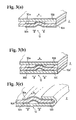
- Figs. 3(a) to 3(c) show portions of the full beads 12 of metal gaskets formed of a plurality of metal base plates.
- the coatings 30a, 30b of the top portions A and foot portions B are made thinner than the other portions, as explained above.
- Fig. 3(a) shows a metal gasket having a two plate structure, i.e. plate 10A and plate 10B;
- Fig. 3(b) shows a metal gasket having a three plate structure, i.e. plate 10A' and plates 10B, 10C;
- Fig. 3(c) shows a metal gasket having a two plate structure with a grommet, i.e. plate 10A and a plate 10D with a curved portion and a flange.
- Figs. 4(a) and 4(b) show portions of half beads 13 of metal gaskets formed of a plurality of metal base plates.
- the coatings 30a, 30b at the shoulder portions C of the half beads 13 are formed thinner than the other portions, as explained above.
- Fig. 4(a) shows a metal gasket having a two plate structure, i.e. plate 10A and plate 10C; and Fig. 4(b) shows a metal gasket having a three plate structure, i.e. plate 10A and plates 10B, 10C.
- a micro seal coating is applied on the upper surface of the metal base plate 10B in Fig. 3(a); the micro seal coating is applied on the upper surface of the metal base plate 10B and the lower surface of the metal base plate 10C in Fig. 3(b); and the micro seal coating is applied on the lower surface of the metal base plate 10D in Fig. 3(c).
- sealing lines for locally generating strong sealing surface pressures are formed around the beads, i.e. the top portion and foot portions of the full bead or the shoulder portion of the half bead, of the metal base plate of the metal gasket.
- the sealing line portions are formed to be thinner than the other portions, the sealing surface pressures at these portions can be lowered.
- the lowering of the sealing surface pressures prevents the coatings from flowing and wearing at the top portion and the foot portions of the full bead, and the shoulder portions of the half bead, which leads to the suppression of the torque-down.
- the coating is continuously formed, the sealing surface pressures can be smoothly changed to improve the sealing property.
- the coating is formed in a belt shape to cover the bead of the metal gasket. Therefore, even if there is a small unevenness, such as a tool mark, on the surface of the engine member against which the coating abuts, the unevenness can be absorbed by the coating to thereby prevent the combustion gas, cooling water or oil from leaking.
- the sealing effect for the smaller unevenness can be increased.
- the metal gasket having good sealing property and durability can be obtained.
Landscapes
- Engineering & Computer Science (AREA)
- General Engineering & Computer Science (AREA)
- Mechanical Engineering (AREA)
- Chemical & Material Sciences (AREA)
- Combustion & Propulsion (AREA)
- Gasket Seals (AREA)
Applications Claiming Priority (2)
| Application Number | Priority Date | Filing Date | Title |
|---|---|---|---|
| JP2001325050A JP2003130224A (ja) | 2001-10-23 | 2001-10-23 | メタルガスケット |
| JP2001325050 | 2001-10-23 |
Publications (2)
| Publication Number | Publication Date |
|---|---|
| EP1306586A2 true EP1306586A2 (de) | 2003-05-02 |
| EP1306586A3 EP1306586A3 (de) | 2004-03-10 |
Family
ID=19141683
Family Applications (1)
| Application Number | Title | Priority Date | Filing Date |
|---|---|---|---|
| EP02023091A Ceased EP1306586A3 (de) | 2001-10-23 | 2002-10-17 | Metalldichtung mit einer partiellen Oberflächenbeschichtung |
Country Status (4)
| Country | Link |
|---|---|
| US (1) | US6893023B2 (de) |
| EP (1) | EP1306586A3 (de) |
| JP (1) | JP2003130224A (de) |
| KR (1) | KR20030033926A (de) |
Families Citing this family (16)
| Publication number | Priority date | Publication date | Assignee | Title |
|---|---|---|---|---|
| JP2004278719A (ja) * | 2003-03-17 | 2004-10-07 | Nippon Leakless Corp | シリンダーヘッド用メタルガスケット |
| DE102005003017B4 (de) * | 2004-01-23 | 2019-10-24 | Koichi Hatamura | Metalldichtung |
| JP2005226806A (ja) * | 2004-02-16 | 2005-08-25 | Ishikawa Gasket Co Ltd | シリンダヘッドガスケット |
| JP3946223B2 (ja) * | 2005-01-26 | 2007-07-18 | 石川ガスケット株式会社 | 金属ガスケット |
| JP4606462B2 (ja) * | 2005-07-21 | 2011-01-05 | Nok株式会社 | 金属製ガスケットの製造方法 |
| DE102006007311A1 (de) * | 2006-02-16 | 2007-08-30 | Federal-Mogul Sealing Systems Bretten Gmbh | Flachdichtung für hohe Beanspruchung für Brennkraftmaschinen |
| JP4721974B2 (ja) * | 2006-07-27 | 2011-07-13 | ヤマハ発動機株式会社 | メタルガスケット |
| US7806413B2 (en) * | 2006-11-08 | 2010-10-05 | Federal-Mogul Corporation | Static gasket |
| JP2009236153A (ja) * | 2008-03-26 | 2009-10-15 | Honda Motor Co Ltd | 吸収式冷凍サイクルの継手構造 |
| JP5311127B2 (ja) * | 2009-04-21 | 2013-10-09 | ニチアス株式会社 | ガスケット用素材 |
| DE102012102834A1 (de) * | 2012-03-08 | 2013-09-12 | Endress + Hauser Gmbh + Co. Kg | Dichtring und Druckaufnehmer mit mindestens einem solchen Dichtring |
| CN105612372B (zh) * | 2013-09-10 | 2018-08-07 | 费德罗-莫格尔公司 | 无涂层汽缸头垫片 |
| WO2015109171A1 (en) | 2014-01-17 | 2015-07-23 | Federal-Mogul Corporation | Gasket component with half-stop and method of manufacturing |
| US10125911B2 (en) * | 2015-12-31 | 2018-11-13 | Thermo King Corporation | Compressor gasket and method of preventing corrosion |
| CN118721887A (zh) | 2020-03-17 | 2024-10-01 | Nok株式会社 | 橡胶金属层叠体和垫片 |
| CN118752862A (zh) | 2020-03-17 | 2024-10-11 | Nok株式会社 | 橡胶金属层叠体和垫片 |
Citations (3)
| Publication number | Priority date | Publication date | Assignee | Title |
|---|---|---|---|---|
| JPH0216861U (de) | 1988-07-20 | 1990-02-02 | ||
| JPH10103523A (ja) | 1996-09-30 | 1998-04-21 | Ishikawa Gasket Kk | メタルガスケット |
| JP2605613Y2 (ja) | 1991-08-27 | 2000-07-31 | エヌオーケー株式会社 | ガスケット |
Family Cites Families (18)
| Publication number | Priority date | Publication date | Assignee | Title |
|---|---|---|---|---|
| US4799695A (en) * | 1982-05-17 | 1989-01-24 | Nihon Metal Gasket Kabushiki Kaisha | Metallic gasket |
| US4397472A (en) * | 1982-11-12 | 1983-08-09 | Felt Products Mfg. Co. | Cylinder head gasket with expanded graphite filler |
| DE69016781T2 (de) * | 1990-05-28 | 1995-09-14 | Nihon Metal Gasket | Metalldichtung. |
| US5150910A (en) * | 1990-07-02 | 1992-09-29 | Ishikawa Gasket Co., Ltd. | Gasket with soft and hard seal coatings |
| JP2691805B2 (ja) * | 1990-07-05 | 1997-12-17 | 日本メタルガスケット株式会社 | 多気筒金属ガスケット |
| EP0468526B1 (de) * | 1990-07-26 | 1995-04-05 | Taiho Kogyo Co., Ltd. | Metalldichtung |
| US5582415A (en) * | 1993-08-31 | 1996-12-10 | Kokusan Parts Industry Co., Ltd. | Metal gasket |
| JP3688024B2 (ja) * | 1995-08-29 | 2005-08-24 | 日本ラインツ株式会社 | 金属ガスケット及びその製造方法 |
| DE19625491C1 (de) * | 1996-06-26 | 1997-10-02 | Payen Goetze Gmbh | Metallische Flachdichtung |
| US5769430A (en) * | 1996-09-30 | 1998-06-23 | Ishikawa Gasket Co., Ltd. | Metal gasket with bead and thermal sprayed layer thereof |
| US6145847A (en) | 1997-01-13 | 2000-11-14 | Nippon Reinz Co., Ltd. | Metal laminate gasket |
| JPH10205620A (ja) * | 1997-01-23 | 1998-08-04 | Nippon Reinz Co Ltd | シリンダヘッド用金属ガスケット |
| JP3745625B2 (ja) * | 1999-05-18 | 2006-02-15 | エルリンククリンガー アクチェンゲゼルシャフト | シリンダヘッドガスケット |
| DE19939869A1 (de) * | 1999-08-23 | 2001-04-12 | Elringklinger Gmbh | Flachdichtung |
| JP2002013640A (ja) * | 2000-06-29 | 2002-01-18 | Uchiyama Mfg Corp | シリンダヘッドガスケット |
| JP2002054740A (ja) * | 2000-08-07 | 2002-02-20 | Ishikawa Gasket Co Ltd | 多気筒用のヘッドガスケット |
| JP2002054745A (ja) * | 2000-08-07 | 2002-02-20 | Ishikawa Gasket Co Ltd | ヘッドガスケット |
| JP3419447B2 (ja) * | 2000-08-07 | 2003-06-23 | 石川ガスケット株式会社 | ヘッドガスケット |
-
2001
- 2001-10-23 JP JP2001325050A patent/JP2003130224A/ja active Pending
-
2002
- 2002-10-10 US US10/267,741 patent/US6893023B2/en not_active Expired - Fee Related
- 2002-10-14 KR KR1020020062356A patent/KR20030033926A/ko not_active Ceased
- 2002-10-17 EP EP02023091A patent/EP1306586A3/de not_active Ceased
Patent Citations (3)
| Publication number | Priority date | Publication date | Assignee | Title |
|---|---|---|---|---|
| JPH0216861U (de) | 1988-07-20 | 1990-02-02 | ||
| JP2605613Y2 (ja) | 1991-08-27 | 2000-07-31 | エヌオーケー株式会社 | ガスケット |
| JPH10103523A (ja) | 1996-09-30 | 1998-04-21 | Ishikawa Gasket Kk | メタルガスケット |
Also Published As
| Publication number | Publication date |
|---|---|
| EP1306586A3 (de) | 2004-03-10 |
| KR20030033926A (ko) | 2003-05-01 |
| JP2003130224A (ja) | 2003-05-08 |
| US20030075875A1 (en) | 2003-04-24 |
| US6893023B2 (en) | 2005-05-17 |
Similar Documents
| Publication | Publication Date | Title |
|---|---|---|
| US6893023B2 (en) | Metal gasket with partial coating | |
| US6682080B2 (en) | Cylinder head gasket | |
| US4828275A (en) | Gasket with elastic sealing members | |
| US5150910A (en) | Gasket with soft and hard seal coatings | |
| US6783132B2 (en) | Cylinder head gasket with seal coatings | |
| US5615898A (en) | Bead seal motorcycle gasket | |
| JP3753413B2 (ja) | 多気筒用のヘッドガスケット | |
| US6986516B2 (en) | Metal gasket with partial coating | |
| US6164662A (en) | Metal gasket | |
| US5893566A (en) | Metal laminate gasket with different coating layers | |
| EP0833086B1 (de) | Metallabdichtung mit Deckschicht | |
| EP0745791A1 (de) | Mehrschichtige Metaldichtung mit Überzuggsschicht | |
| JP3419447B2 (ja) | ヘッドガスケット | |
| US5205569A (en) | Metal laminate gasket with graphite sheet | |
| US6981703B2 (en) | Cylinder head gasket | |
| EP0486150B2 (de) | Geschichtete Stahlblechabdichtung mit Schutzteil | |
| EP0508017B1 (de) | Flachdichtung aus Metalllaminat mit einer Graphitschicht | |
| EP1179696A2 (de) | Zylinderkopfdichtung mit Schicht zur Einstellung der Dicke | |
| EP1544518A1 (de) | Zylinderkopfdichtung | |
| JP3769523B2 (ja) | シリンダヘッドガスケット | |
| KR20020012485A (ko) | 헤드 개스킷 | |
| JPH0483975A (ja) | 金属ガスケット |
Legal Events
| Date | Code | Title | Description |
|---|---|---|---|
| PUAI | Public reference made under article 153(3) epc to a published international application that has entered the european phase |
Free format text: ORIGINAL CODE: 0009012 |
|
| AK | Designated contracting states |
Designated state(s): AT BE BG CH CY CZ DE DK EE ES FI FR GB GR IE IT LI LU MC NL PT SE SK TR |
|
| AX | Request for extension of the european patent |
Extension state: AL LT LV MK RO SI |
|
| PUAL | Search report despatched |
Free format text: ORIGINAL CODE: 0009013 |
|
| AK | Designated contracting states |
Kind code of ref document: A3 Designated state(s): AT BE BG CH CY CZ DE DK EE ES FI FR GB GR IE IT LI LU MC NL PT SE SK TR |
|
| AX | Request for extension of the european patent |
Extension state: AL LT LV MK RO SI |
|
| 17P | Request for examination filed |
Effective date: 20040505 |
|
| 17Q | First examination report despatched |
Effective date: 20040827 |
|
| AKX | Designation fees paid |
Designated state(s): DE FR GB IT |
|
| STAA | Information on the status of an ep patent application or granted ep patent |
Free format text: STATUS: THE APPLICATION HAS BEEN REFUSED |
|
| 18R | Application refused |
Effective date: 20060405 |