EP1306603B1 - Procédé et dispositif de commande d'une fonction relative à la sécurité d'une machine - Google Patents
Procédé et dispositif de commande d'une fonction relative à la sécurité d'une machine Download PDFInfo
- Publication number
- EP1306603B1 EP1306603B1 EP02021518A EP02021518A EP1306603B1 EP 1306603 B1 EP1306603 B1 EP 1306603B1 EP 02021518 A EP02021518 A EP 02021518A EP 02021518 A EP02021518 A EP 02021518A EP 1306603 B1 EP1306603 B1 EP 1306603B1
- Authority
- EP
- European Patent Office
- Prior art keywords
- safety
- machine
- region
- movement
- danger
- Prior art date
- Legal status (The legal status is an assumption and is not a legal conclusion. Google has not performed a legal analysis and makes no representation as to the accuracy of the status listed.)
- Expired - Lifetime
Links
- 238000000034 method Methods 0.000 title claims description 18
- 238000012544 monitoring process Methods 0.000 claims abstract description 20
- 230000035515 penetration Effects 0.000 claims description 5
- 230000001419 dependent effect Effects 0.000 claims description 4
- 230000011664 signaling Effects 0.000 claims description 4
- 230000001960 triggered effect Effects 0.000 abstract description 7
- 238000011156 evaluation Methods 0.000 description 11
- 238000013459 approach Methods 0.000 description 6
- 230000004888 barrier function Effects 0.000 description 3
- 238000005452 bending Methods 0.000 description 3
- 238000011161 development Methods 0.000 description 3
- 230000005693 optoelectronics Effects 0.000 description 3
- 230000001681 protective effect Effects 0.000 description 3
- 230000000007 visual effect Effects 0.000 description 3
- 230000003287 optical effect Effects 0.000 description 2
- 238000006243 chemical reaction Methods 0.000 description 1
- 238000001514 detection method Methods 0.000 description 1
- 230000000694 effects Effects 0.000 description 1
- 231100001261 hazardous Toxicity 0.000 description 1
- 230000000149 penetrating effect Effects 0.000 description 1
- 230000007704 transition Effects 0.000 description 1
Images


Classifications
-
- F—MECHANICAL ENGINEERING; LIGHTING; HEATING; WEAPONS; BLASTING
- F16—ENGINEERING ELEMENTS AND UNITS; GENERAL MEASURES FOR PRODUCING AND MAINTAINING EFFECTIVE FUNCTIONING OF MACHINES OR INSTALLATIONS; THERMAL INSULATION IN GENERAL
- F16P—SAFETY DEVICES IN GENERAL; SAFETY DEVICES FOR PRESSES
- F16P3/00—Safety devices acting in conjunction with the control or operation of a machine; Control arrangements requiring the simultaneous use of two or more parts of the body
- F16P3/12—Safety devices acting in conjunction with the control or operation of a machine; Control arrangements requiring the simultaneous use of two or more parts of the body with means, e.g. feelers, which in case of the presence of a body part of a person in or near the danger zone influence the control or operation of the machine
- F16P3/14—Safety devices acting in conjunction with the control or operation of a machine; Control arrangements requiring the simultaneous use of two or more parts of the body with means, e.g. feelers, which in case of the presence of a body part of a person in or near the danger zone influence the control or operation of the machine the means being photocells or other devices sensitive without mechanical contact
- F16P3/144—Safety devices acting in conjunction with the control or operation of a machine; Control arrangements requiring the simultaneous use of two or more parts of the body with means, e.g. feelers, which in case of the presence of a body part of a person in or near the danger zone influence the control or operation of the machine the means being photocells or other devices sensitive without mechanical contact using light grids
-
- F—MECHANICAL ENGINEERING; LIGHTING; HEATING; WEAPONS; BLASTING
- F16—ENGINEERING ELEMENTS AND UNITS; GENERAL MEASURES FOR PRODUCING AND MAINTAINING EFFECTIVE FUNCTIONING OF MACHINES OR INSTALLATIONS; THERMAL INSULATION IN GENERAL
- F16P—SAFETY DEVICES IN GENERAL; SAFETY DEVICES FOR PRESSES
- F16P3/00—Safety devices acting in conjunction with the control or operation of a machine; Control arrangements requiring the simultaneous use of two or more parts of the body
- F16P3/12—Safety devices acting in conjunction with the control or operation of a machine; Control arrangements requiring the simultaneous use of two or more parts of the body with means, e.g. feelers, which in case of the presence of a body part of a person in or near the danger zone influence the control or operation of the machine
- F16P3/14—Safety devices acting in conjunction with the control or operation of a machine; Control arrangements requiring the simultaneous use of two or more parts of the body with means, e.g. feelers, which in case of the presence of a body part of a person in or near the danger zone influence the control or operation of the machine the means being photocells or other devices sensitive without mechanical contact
- F16P3/142—Safety devices acting in conjunction with the control or operation of a machine; Control arrangements requiring the simultaneous use of two or more parts of the body with means, e.g. feelers, which in case of the presence of a body part of a person in or near the danger zone influence the control or operation of the machine the means being photocells or other devices sensitive without mechanical contact using image capturing devices
Definitions
- the invention relates to methods for controlling at least one safety-related function of a machine in which a surveillance area is monitored by at least one sensor and a position of an object is detected and the monitoring area a includes a safety margin delimiting a danger area, a safety distance to a hazardous point of the Machine defines, and penetration into the danger area the safety relevant Function triggers.
- the invention further relates to a device for Implementation of the procedures.
- protection is provided in the simplest way by an access to or an intervention in a danger area mechanically, for example secured by grating or barrier fences.
- a mechanical protection it also makes access to the machine difficult during one Machine downtime, so that today optoelectronic preferred Protective devices are used.
- the safety-relevant function which usually means stopping the machine is triggered.
- the Protective devices e.g., photoelectric sensors and light curtains
- the Protective devices provide sufficient Distance to the actual danger spot. It has to be, for example be sure that even with a very fast movement, for example in case of a fall of the operator, the machine still in time to a standstill comes before the person in any way with the danger zone of the Machine could come into contact. It can from the safety device not between slow and careful movements of the operator and careless, may be fast movements, a higher Accident potential have to be differentiated. For security reasons then always triggered the safety-relevant function.
- an area to be monitored of at least one Local and time-resolved sensor monitors, with which the position, the Direction of movement and / or the speed of movement of an object, for example, an operator or individual limbs of the operator, be recognized. Furthermore, in the monitoring area is in itself well-known way defined a safety boundary, which is a danger area delimits and sets a safe distance to the dangerous movement of the Defines machine as minimum distance.
- a safety boundary which is a danger area delimits and sets a safe distance to the dangerous movement of the Defines machine as minimum distance.
- the safety limit and thus the size of the danger zone is no longer fixed rigidly, but will according to the position of the operator in the Room and the movement of this person adapted. Due to the situational Adjustment of the safety boundary may be the monitored area, which is usually an access area to the machine, much better utilized not every movement, even if they run close to the machine will trigger the safety-related function. So can one slow approach to the danger zone only a slow deceleration enable the dangerous movement of the machine. A complete Stopping does not necessarily have to be necessary. A quick approach can be made in known to trigger an emergency stop of the machine. A movement parallel to Danger point or away from the danger point can restart the Machine does not effect or at least the safety-relevant function trigger.
- the safety-related function can have different system reactions contain. It is conceivable that when moving towards the Hazard spot located at a greater distance from the danger point plays, only a visual and / or audible warning is generated and at further approximation only a slowing down of the dangerous movement takes place, the braking on further approach to a complete stop can lead the machine.
- the machine running time can be achieved by the method according to the invention be increased because with the inventive method, only the actual dangerous situations can be detected and only these situations stop the machine, but less dangerous ones Situations can only slow down the machine movement and not necessarily have to cause an emergency stop.
- the problem is also solved by another method, in which instead of a sharply defined security boundary a security area with a finite Extension is provided and where the extent of the security area depending on the position, the direction of movement and / or Movement speed of the object set in the monitoring area becomes. Only a complete crossing of the entire security area triggers the safety-relevant function. An entrance to the security area can trigger a visual and / or audible warning. This is similar Way, as in the first solution, the security area with the situation same benefits customizable.
- a speed with which the location of the safety boundary or the security area, depending on the location Movement direction and / or movement speed of the object in Monitoring area For example, during a slow movement of the Object in the direction of the danger spot, the safety barrier slowly before the Object be pushed in the direction of the danger point and only at extreme rimpedement will not be postponed, leaving another Move the object to the danger spot, then the safety relevant would trigger function.
- the object in the surveillance area be classified. This allows between an operator to protect it the safety limit is set and other non-vulnerable objects, for which no safety limit is to be defined. Not one endangered object could be, for example, a material transport car.
- the safety-relevant function of the machine is then dependent on the Class of the object controlled.
- the safety-relevant Function of the machine adjusted. For example, at slow approach to the danger area only produces a warning sound where, on the other hand, in the case of a rapid approach to the danger zone, the Warning sound amplified or the machine even completely in a safe state can go over.
- the object of the invention is also achieved by said method corresponding devices solved.
- a device for controlling the safety-related function on a monitoring area in which a Object of at least one location and time resolution sensor can be monitored.
- an evaluation unit are from the sensor signals position, direction of movement and / or movement speed of the object in the surveillance area determinable.
- the device has means for fixing the Safety limit on, with the location of the safety boundary in the Monitoring range can be specified depending on the situation.
- To trigger the safety-relevant function are appropriate signal and / or switching means intended.
- the device according to the alternative method differs only by the fact that the means for setting the security limit at the same time also specify the extent of the security area depending on the situation can. These means for setting the security limit or to Setting the extent of the security area may be a act accordingly programmable circuit of the evaluation.
- the devices Object classifier for classifying the objects so that the safety relevant function of the machine depending on the class of the Object is controllable.
- the object classifiers may also be incorporated into the Evaluation unit circuit and / or program technology to be integrated.
- the sensor 14 may be or be a camera any other location and time-resolved sensor, such as a Laser scanner, as distributed by the applicant under the name "PLS" becomes.
- PLS Laser scanner
- two cameras 14 and 16 be provided to a three-dimensional detection of a To allow monitoring area 18.
- At special danger spots like For example, in the pressing area 20 of the machine 12, could at least one other Sensor 22 may be arranged.
- the sensors 14, 16, 22 are over Signal lines connected to an evaluation unit 28, in which the sensor signals can be evaluated.
- the evaluation unit 28 is via a suitable Connection 30 connected to the machine 12 to trigger at least one control safety-related function.
- the security relevant Function may be an emergency stop of the machine and / or only an acoustic and / or be an optical warning signal.
- the machine 12 or the device 10 Signaling and / or switching means, for example, a in Fig. 1 schematically can be shown off switch 46 and / or a warning light 48.
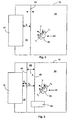
- Figures 2 and 3 the work area of Figure 1, consisting of machine 12 and monitoring area 18, shown in a plan view.
- the Device 10 according to the invention with the sensors 14 and 16 and the Evaluation unit 28 is not recognizable in this representation.
- Figures 2 and 3 thus show an image of how the sensor 14 (or 16) "sees”.
- the sensor 14 (resp. 16) is able to detect the entire surveillance area 18 in which also the machine 12 and the person 26, are located.
- the sensor 14 and the Evaluation unit 28 are formed with an image recognition to the person 26 as to recognize an object to be protected.
- object recognition can work in detail is from the state of the art, like it For example, DE 44 17 128 A1 shows known.
- the monitoring area 18 is through a security boundary 32 in a safe area 34 and secured by the security boundary 32 Danger zone 36 divided. If the person 26 the security limit 32 exceeds or, for example, with the arm in the danger area 36th extends beyond the evaluation unit 28 a safety-relevant function, For example, an emergency stop the machine 12, via the signal and / or switching means 46 or 48 triggered.
- the safety limit 32 is not a physically recognizable limit, but becomes via corresponding means 47 in the evaluation unit 28, for example software-based.
- the means 47 for setting the safety limit can exist in a programmable circuit.
- the safety limit 32 has a safety distance S to the machine 12 and defines the size of the Danger zone 36. According to the invention, this safety distance S, ie the Position of the safety limit 32, via the means 47 variably fixable in Depending on the position, the direction of movement and / or the Movement speed v of the person 26.
- the position, direction of movement and / or movement speed v of the person 26 can be determined via the sensors 14 and 16 and the evaluation unit 28 in a manner known per se (see eg DE 44 17 128 A1).
- the movement speed v of the person 26, is composed of a component v II parallel to the machine 12 and a component v ⁇ perpendicular to the machine 12.
- a movement with an exclusive component v II parallel to the machine can not cause any dangers.
- From a security point of view only the component v ⁇ ie the effective approach speed , is important. If v ⁇ large, then the safety distance S should also be large. Is v ⁇ but small, ie the person 26 moves only slowly to the machine 12, the safety limit 32 can be placed closer to the machine 12.
- the speed at which the position of the safety limit is shifted is, on the one hand, dependent on the position of the person 26 and, on the other hand, on the speed component v ⁇ .
- the safety-related feature that in the case of the press can be a slow closing movement, is thus of the Position, the direction of movement and / or the speed of movement v of the Person 26 dependent.
- the safe slow movement can be stopped if the person 26 still moves within the security area 38, however moves away from the machine 12, so the distance to the machine 12th increased.
- Distances S 1 and S 2 of the left and right boundaries 42, 40 of the security area 38 from the machine 12 can be set variably by the means 47. They are preferably determined as a function of the position, the direction of movement and / or the speed of movement v of the person 26 so that, on the one hand, the extent A of the security area 38 can be adapted to the situation and, on the other hand, the position of the security area 38, ie the distance to the machine 12, depending on the situation is customizable.
- FIG Material Handling Car could be. If the object 44 in the Security area 38 or even enters the danger zone 34, the safety-relevant function can not be triggered because of the object 44th can pose no danger, since the material handling carriage 44, for example never penetrate into the pressing area 20 of the machine 12.
- the device 10 according to the invention
- Object classification means 49 consisting of suitable software and hardware, which is integrated in the evaluation unit 28 could exist.
- the recognized objects 24 and 44 are in classes divided so that the safety-related functions, such as warning signals or Emergency stops, depending on the class of the in the security area 38 or the danger zone 36 penetrating objects can be controlled.
- Objects like the material handling car 44 are for this purpose in a class of grouped around dangerous objects, whereas by the inventive Device recognized persons 26 in a class of vulnerable objects be grouped for the security limit 32 or the security area 38 must be established.
- the machine running time is increased by the invention and the Used more effectively on the one hand the expansion of the secured danger area 36 is situational adaptable and not every Movement by a person or other object near the Machine is running, must cause an emergency stop of the machine and on the other hand, not every intrusion of an object into the danger area 36 causes an emergency stop.
- the invention can be used on a wide variety of types of machines.
- the machine may be an industrial robot 50, such as is shown schematically in Figure 4, act.
- the invention Device can now a pivoting range of a robot arm 52, the position of the Robot arm and the direction of movement 56, 58 and movement speed of the robot arm 52 are detected. At the same time, the position, the Direction of movement and speed of movement in the area of the robot 50 working person 54 are recognized.
- the device according to the invention 10 can control the robot's operation in safety-related aspects so that it is ensured that the robot 50 and person 54 never meet and the person 54 near the robot arm 52 never gets hurt.
- the robot 50 does not have a large area by a Be secured locking zone, but on the inventive device 10 can the scope of protection around the robotic arm 52 is variable according to the situation be determined and with the robot arm 52 "mitwandern". This is one improved work in the field of an industrial robot or even one safe cooperation between the robot 50 and the person 54 possible.
Landscapes
- Engineering & Computer Science (AREA)
- General Engineering & Computer Science (AREA)
- Mechanical Engineering (AREA)
- Manipulator (AREA)
- Safety Devices In Control Systems (AREA)
- Control Of Positive-Displacement Air Blowers (AREA)
- Bending Of Plates, Rods, And Pipes (AREA)
- Presses And Accessory Devices Thereof (AREA)
- Operation Control Of Excavators (AREA)
- Component Parts Of Construction Machinery (AREA)
Claims (11)
- Procédé de commande d'au moins une fonction relative à la sécurité d'une machine (12) dans lequel une zone à surveiller (18) est surveillée par au moins un capteur (14, 16, 22) analysant l'espace et le temps; la position, le sens de déplacement et/ou la vitesse de déplacement (v) d'un objet (24, 26) sont reconnus ; la zone à surveiller (18) comprend une limite de sécurité (32) délimitant une zone de danger (36) et définissant une distance de sécurité (S) par rapport à un endroit dangereux de la machine (12) ; une pénétration dans la zone de danger (36) déclenche la fonction relative à la sécurité ; et dans lequel la situation de la limite de sécurité (32) peut être établie de manière variable en fonction de la position, du sens de déplacement et/ou de la vitesse de déplacement (v).
- Procédé selon la revendication 1, caractérisé en ce que la vitesse avec laquelle la situation de la limite de sécurité (32) est déplacée est fonction de la position, du sens de déplacement et/ou de la vitesse de déplacement (v) de l'objet (24, 26).
- Procédé de commande d'au moins une fonction relative à la sécurité d'une machine (12), notamment selon l'une des revendications précédentes, dans lequel la zone à surveiller (18) est surveillée par au moins un capteur analysant l'espace et le temps (14, 16, 22) ; la position, le sens de déplacement et/ou la vitesse de déplacement (v) d'un objet (24, 26) sont reconnus ; la zone à surveiller (18) comprend une zone de sécurité (38) délimitant une zone de danger (36) ; une pénétration dans la zone de danger (36) déclenche la fonction relative à la sécurité ; et dans lequel une extension (A) de la zone limite de sécurité (38) peut être établie de manière variable en fonction de la position, du sens de déplacement et/ou de la vitesse de déplacement (v) de l'objet (24, 26).
- Procédé selon l'une des revendications précédentes, caractérisé en ce que l'objet (24, 26, 44) est classifié à l'aide d'un moyen de classification d'objet (46).
- Procédé selon la revendication 4, caractérisé en ce que la fonction relative à la sécurité de la machine est commandée en fonction de la classe de l'objet (26, 44).
- Procédé selon l'une des revendications précédentes, caractérisé en ce que la fonction relative à la sécurité de la machine est commandée en fonction de la position, du sens de déplacement et/ou de la vitesse de déplacement (v) de l'objet (26).
- Dispositif de commande d'au moins une fonction relative à la sécurité d'une machine (12) comportant une zone à surveiller (18) dans laquelle un objet (24, 26) peut être surveillé par au moins un capteur analysant l'espace et le temps (14, 16, 22), une unité de traitement (28) servant à déterminer la position, le sens de déplacement et/ou la vitesse de déplacement (v) de l'objet (26) à partir des signaux de capteur, des moyens (47) servant à établir une limite de sécurité (32) délimitant une zone de danger (36) et définissant une distance de sécurité (S) par rapport à la machine (12), la situation de la limite de sécurité (32) dans la zone à surveiller (18) pouvant être fixée en fonction de la position, du sens de déplacement et/ou de la vitesse de déplacement (v) de l'objet (26) ; et des moyens de signalisation et/ou de commutation (46, 48) servant à déclencher la fonction relative à la sécurité après pénétration dans la zone de danger (36).
- Dispositif de commande d'au moins une fonction relative à la sécurité d'une machine (12), notamment selon la revendication 7, comportant une zone à surveiller (18) dans laquelle un objet (26) peut être surveillé par au moins un capteur analysant l'espace et le temps (14, 16, 22), une unité de traitement (28) servant à déterminer la position, le sens de déplacement et/ou la vitesse de déplacement (v) de l'objet (26) à partir des signaux de capteur, des moyens (47) servant à établir, dans la zone à surveiller (18), l'extension d'une zone de sécurité (38) délimitant une zone de danger (36), une extension (A) de la zone de sécurité (38) pouvant être établie de manière variable en fonction de la position, du sens de déplacement et/ou de la vitesse de déplacement (v) de l'objet (26) ; et des moyens de signalisation et/ou de commutation (46, 48) servant à déclencher la fonction relative à la sécurité après pénétration dans la zone de danger (36).
- Dispositif selon l'une des revendications précédentes 7 et 8, caractérisé en ce que la fonction relative à la sécurité de la machine (12) peut être commandée en fonction de la position, du sens de déplacement et/ou de la vitesse de déplacement (v) de l'objet (26).
- Dispositif selon l'une des revendications précédentes 7 à 9, caractérisé en ce qu'il existe au moins un moyen de classification d'objet (46) servant à classifier l'objet (26, 44).
- Dispositif selon la revendication 10, caractérisé en ce que la fonction relative à la sécurité de la machine peut être commandée en fonction de la classe de l'objet (26, 44).
Applications Claiming Priority (2)
| Application Number | Priority Date | Filing Date | Title |
|---|---|---|---|
| DE10152543A DE10152543A1 (de) | 2001-10-24 | 2001-10-24 | Verfahren und Vorrichtung zum Steuern einer sicherheitsrelevanten Funktion einer Maschine |
| DE10152543 | 2001-10-24 |
Publications (4)
| Publication Number | Publication Date |
|---|---|
| EP1306603A2 EP1306603A2 (fr) | 2003-05-02 |
| EP1306603A3 EP1306603A3 (fr) | 2004-03-31 |
| EP1306603B1 true EP1306603B1 (fr) | 2005-03-02 |
| EP1306603B2 EP1306603B2 (fr) | 2011-06-29 |
Family
ID=7703604
Family Applications (1)
| Application Number | Title | Priority Date | Filing Date |
|---|---|---|---|
| EP02021518A Expired - Lifetime EP1306603B2 (fr) | 2001-10-24 | 2002-09-26 | Procédé et dispositif de commande d'une fonction relative à la sécurité d'une machine |
Country Status (5)
| Country | Link |
|---|---|
| US (1) | US6778092B2 (fr) |
| EP (1) | EP1306603B2 (fr) |
| JP (1) | JP2003222295A (fr) |
| AT (1) | ATE290186T1 (fr) |
| DE (2) | DE10152543A1 (fr) |
Cited By (2)
| Publication number | Priority date | Publication date | Assignee | Title |
|---|---|---|---|---|
| EP3524870B1 (fr) | 2018-02-08 | 2020-11-04 | Omron Europe B.V. | Dispositif de surveillance et procédé de surveillance d'une zone surveillée |
| EP3916286A1 (fr) | 2020-05-29 | 2021-12-01 | Sick Ag | Capteur optoélectronique de sécurité et procédé de sécurisation d'une machine |
Families Citing this family (149)
| Publication number | Priority date | Publication date | Assignee | Title |
|---|---|---|---|---|
| JP3716803B2 (ja) * | 2002-03-07 | 2005-11-16 | オムロン株式会社 | リスク評価支援装置及びプログラム製品 |
| EP1552214B1 (fr) * | 2002-06-11 | 2011-10-26 | Kevin Stephen Davies | Systeme de securite |
| JP4513568B2 (ja) * | 2002-07-18 | 2010-07-28 | 株式会社安川電機 | ロボット制御装置 |
| JP4066168B2 (ja) * | 2003-03-13 | 2008-03-26 | オムロン株式会社 | 侵入物監視装置 |
| DE10324517A1 (de) * | 2003-05-28 | 2004-12-16 | Daimlerchrysler Ag | Roboter und Anlernverfahren dafür |
| DE10324628A1 (de) * | 2003-05-28 | 2004-12-16 | Daimlerchrysler Ag | Steuerverfahren für einen Roboter |
| DE10360789B4 (de) * | 2003-12-23 | 2007-03-15 | Leuze Lumiflex Gmbh + Co. Kg | Vorrichtung zur Überwachung eines Erfassungsbereichs an einem Arbeitsmittel |
| DE102004020024A1 (de) * | 2004-04-23 | 2005-11-10 | Sick Ag | Verfahren zur Sicherung einer Werkzeugmaschine und optoelektronischer Sensor zur Durchführung eines solchen Verfahrens |
| BRPI0511407A (pt) * | 2004-05-03 | 2008-01-22 | Webb Int Co Jerwis B | sistema para carga automática de transporte utilizando o método de referência cruzada |
| US8210791B2 (en) | 2004-05-03 | 2012-07-03 | Jervis B. Webb Company | Automatic transport loading system and method |
| US8192137B2 (en) | 2004-05-03 | 2012-06-05 | Jervis B. Webb Company | Automatic transport loading system and method |
| US8075243B2 (en) | 2004-05-03 | 2011-12-13 | Jervis B. Webb Company | Automatic transport loading system and method |
| US7980808B2 (en) * | 2004-05-03 | 2011-07-19 | Jervis B. Webb Company | Automatic transport loading system and method |
| JP2005324297A (ja) * | 2004-05-17 | 2005-11-24 | Matsushita Electric Ind Co Ltd | ロボット |
| DE102004041821A1 (de) | 2004-08-27 | 2006-03-16 | Abb Research Ltd. | Vorrichtung und Verfahren zur Sicherung eines maschinell gesteuerten Handhabungsgerätes |
| DE102004043514A1 (de) * | 2004-09-08 | 2006-03-09 | Sick Ag | Verfahren und Vorrichtung zum Steuern einer sicherheitsrelevanten Funktion einer Maschine |
| DE102004043515A1 (de) * | 2004-09-08 | 2006-03-09 | Sick Ag | Verfahren und Vorrichtung zum Erfassen eines Objekts |
| US8132225B2 (en) | 2004-09-30 | 2012-03-06 | Rockwell Automation Technologies, Inc. | Scalable and flexible information security for industrial automation |
| DE102004048563A1 (de) * | 2004-10-04 | 2006-04-13 | Benteler Automobiltechnik Gmbh | Überwachungseinrichtung für Roboter |
| WO2006043396A1 (fr) * | 2004-10-19 | 2006-04-27 | Matsushita Electric Industrial Co., Ltd. | Appareil robot |
| DE102004055229A1 (de) * | 2004-11-17 | 2006-05-18 | Heidelberger Druckmaschinen Ag | Zustandsabhängige Absicherung von Maschinen |
| DE102005006557A1 (de) * | 2005-02-11 | 2006-08-31 | Zf Friedrichshafen Ag | Anschlagpuffer für eine Tür oder Klappe eines Kraftfahrzeugs |
| DE102005011143A1 (de) * | 2005-03-10 | 2006-09-14 | Sick Ag | Vorrichtung und Verfahren zum Steuern einer sicherheitsrelevanten Funktion |
| US7328871B2 (en) * | 2005-04-14 | 2008-02-12 | Progressive Rail Technologies, Inc. | Railroad car coupler gap analyzer |
| FR2884591B1 (fr) * | 2005-04-15 | 2010-10-08 | Goss Int Montataire Sa | Systeme de securite et presse correspondante |
| US7708232B2 (en) * | 2005-05-19 | 2010-05-04 | Progressive Rail Technologies, Inc. | Railroad car lateral instability and tracking error detector |
| JP4764070B2 (ja) * | 2005-05-24 | 2011-08-31 | 本田技研工業株式会社 | 作業ステーションの安全システム |
| US20060276958A1 (en) * | 2005-06-02 | 2006-12-07 | Jervis B. Webb Company | Inertial navigational guidance system for a driverless vehicle utilizing laser obstacle sensors |
| EP1790474A1 (fr) * | 2005-11-28 | 2007-05-30 | Kba-Giori S.A. | Machine d'impression sur feuilles ou sur bobines |
| WO2007067898A2 (fr) * | 2005-12-05 | 2007-06-14 | Global Precision Solutions, Llp. | Correction de distance pour systeme de prevention de dommages |
| FR2894318B1 (fr) * | 2005-12-07 | 2008-03-07 | Lectra Sa | Procede de gestion de securite active pour une machine de travail automatique. |
| EP1820611B1 (fr) * | 2006-02-17 | 2008-10-08 | Abb Research Ltd. | Système robotisé industriel |
| DE102006012823B4 (de) * | 2006-03-21 | 2016-12-22 | Leuze Electronic Gmbh + Co. Kg | Vorrichtung zur Überwachung eines Gefahrenbereichs an einem Arbeitsmittel |
| JP5035768B2 (ja) * | 2006-04-18 | 2012-09-26 | 独立行政法人産業技術総合研究所 | 人間ロボット共存作業用安全装置 |
| US20070279525A1 (en) * | 2006-06-01 | 2007-12-06 | Kuohua Wu | Audience detection for increasing component longevity |
| DE102006048163B4 (de) | 2006-07-31 | 2013-06-06 | Pilz Gmbh & Co. Kg | Kamerabasierte Überwachung bewegter Maschinen und/oder beweglicher Maschinenelemente zur Kollisionsverhinderung |
| DE102006046759B4 (de) * | 2006-09-29 | 2018-05-17 | Abb Ag | Verfahren zur Erhöhung der Sicherheit beim Betrieb eines Roboters |
| DE102007006708A1 (de) | 2007-02-10 | 2008-08-14 | Abb Research Ltd. | Verfahren zur Sicherung eines Handhabungsgeräts |
| DE102007013299A1 (de) * | 2007-03-06 | 2008-09-11 | Cedes Ag | Sensorvorrichtung sowie Anlage mit einem Förderer und einer Sensorvorrichtung |
| JP5377837B2 (ja) * | 2007-05-31 | 2013-12-25 | 株式会社キーエンス | 光電センサ |
| DE102007028390A1 (de) * | 2007-06-15 | 2008-12-18 | Abb Research Ltd. | Prozesssteuerung, System und Verfahren zur automatisierten Anpassung von Prozessparametern wenigstens einer Handhabungsvorrichtung |
| JP2009050958A (ja) * | 2007-08-27 | 2009-03-12 | Fanuc Ltd | 停止監視機能を備えたロボット制御装置 |
| JP4986154B2 (ja) * | 2007-10-05 | 2012-07-25 | 独立行政法人産業技術総合研究所 | ロボット、ロボット制御装置、ロボット制御プログラム、ロボット制御プログラムを作成するためのシミュレータ |
| DE102007048684B4 (de) * | 2007-10-10 | 2010-09-09 | Polysius Ag | Laborsystem |
| JP5190761B2 (ja) * | 2008-01-10 | 2013-04-24 | 株式会社Ihi | 移動ロボットの監視装置および監視方法 |
| EP2083209B1 (fr) * | 2008-01-28 | 2012-10-17 | Sick Ag | Système de sécurité destiné à la mesure sans contact de voies et/ou de vitesses |
| ATE537526T1 (de) | 2008-02-20 | 2011-12-15 | Sick Ag | Überwachung mit einem sensorelement |
| DE102008013431A1 (de) * | 2008-03-10 | 2009-05-07 | Siemens Aktiengesellschaft | Verfahren und Vorrichtung zum sicherheitsgerichteten Stillsetzen einer Maschine |
| EP2294544A4 (fr) | 2008-04-30 | 2013-01-16 | Ecolab Inc | Pratiques de nettoyage et de désinfection d'installation de soins de santé validées |
| US8639527B2 (en) | 2008-04-30 | 2014-01-28 | Ecolab Usa Inc. | Validated healthcare cleaning and sanitizing practices |
| TW201033372A (en) | 2008-10-29 | 2010-09-16 | Sms Siemag Ag | Robot interaction system |
| JP2010120139A (ja) * | 2008-11-21 | 2010-06-03 | New Industry Research Organization | 産業用ロボットの安全制御装置 |
| WO2010060475A1 (fr) * | 2008-11-26 | 2010-06-03 | Abb Research Ltd. | Robot industriel |
| DE202008016093U1 (de) * | 2008-12-05 | 2010-04-15 | Sick Ag | Überwachungssensor |
| DE102009010460B4 (de) * | 2009-02-13 | 2010-11-25 | Pilz Gmbh & Co. Kg | Vorrichtung und Verfahren zum Bestimmen der Nachlaufzeit einer Maschine |
| JP5343641B2 (ja) * | 2009-03-12 | 2013-11-13 | 株式会社Ihi | ロボット装置の制御装置及びロボット装置の制御方法 |
| JP5229902B2 (ja) * | 2009-03-30 | 2013-07-03 | 独立行政法人産業技術総合研究所 | 侵入検知機能付き安全位置検出装置 |
| DE202009006683U1 (de) * | 2009-05-08 | 2010-09-30 | Sick Ag | Zugangsabsicherungssystem |
| EP2441063B1 (fr) | 2009-06-12 | 2015-03-11 | Ecolab USA Inc. | Surveillance de l'observance de l'hygiène des mains |
| USRE48951E1 (en) | 2015-08-05 | 2022-03-01 | Ecolab Usa Inc. | Hand hygiene compliance monitoring |
| DE102009034848B4 (de) | 2009-07-27 | 2014-02-20 | Sick Ag | Optoelektronischer Sensor |
| US20110168037A1 (en) * | 2010-01-11 | 2011-07-14 | The Texas A&M University System | Autonomous module builder |
| EP2386876B1 (fr) | 2010-05-04 | 2013-07-10 | Sick AG | Capteur de sécurité optoélectronique mesurant l'éloignement et procédé de surveillance d'une zone de surveillance |
| EP2569762A4 (fr) * | 2010-05-12 | 2015-05-20 | Proxisafe Ltd | Système d'avertissement d'événement et procédé associé |
| US20110298579A1 (en) * | 2010-06-08 | 2011-12-08 | Cedes Safety & Automation Ag | Dynamically adaptable safety zones |
| EP2395372B1 (fr) * | 2010-06-09 | 2013-10-09 | Sick AG | Scanner de sécurité |
| US8781629B2 (en) | 2010-09-22 | 2014-07-15 | Toyota Motor Engineering & Manufacturing North America, Inc. | Human-robot interface apparatuses and methods of controlling robots |
| US20120095575A1 (en) * | 2010-10-14 | 2012-04-19 | Cedes Safety & Automation Ag | Time of flight (tof) human machine interface (hmi) |
| DE102010050547A1 (de) * | 2010-11-05 | 2012-05-10 | Kuka Laboratories Gmbh | Verfahren und Vorrichtung zur Sicherheitsüberwachung eines Roboters |
| DE102010063125A1 (de) * | 2010-12-15 | 2012-06-21 | Robert Bosch Gmbh | Verfahren und Vorrichtung zur sicheren Übertragung von elektromagnetischer Energie |
| DE102010063214A1 (de) | 2010-12-16 | 2012-06-21 | Robert Bosch Gmbh | Sicherungseinrichtung für eine Handhabungsvorrichtung, insbesondere einen Industrieroboter, sowie Verfahren zum Betreiben der Sicherungseinrichtung |
| WO2012098609A1 (fr) * | 2011-01-17 | 2012-07-26 | パナソニック株式会社 | Dispositif de sécurité et procédé de détermination d'une action préliminaire |
| US20140210620A1 (en) | 2013-01-25 | 2014-07-31 | Ultraclenz Llc | Wireless communication for dispenser beacons |
| CN102810239A (zh) * | 2011-05-31 | 2012-12-05 | 鸿富锦精密工业(深圳)有限公司 | 意外防止系统及方法 |
| JP5378479B2 (ja) * | 2011-10-31 | 2013-12-25 | 株式会社キーエンス | 光電センサ及びその設定方法 |
| CN103192414B (zh) * | 2012-01-06 | 2015-06-03 | 沈阳新松机器人自动化股份有限公司 | 一种基于机器视觉的机器人防撞保护装置及方法 |
| DE102012007242A1 (de) * | 2012-03-09 | 2013-09-12 | Fraunhofer-Gesellschaft zur Förderung der angewandten Forschung e.V. | Vorrichtung und Verfahren zur sicheren Mensch-Roboter-Kooperation |
| JP5970880B2 (ja) * | 2012-03-15 | 2016-08-17 | オムロン株式会社 | 動力源の制御装置 |
| DE102012102236A1 (de) | 2012-03-16 | 2013-09-19 | Pilz Gmbh & Co. Kg | Verfahren und Vorrichtung zum Absichern eines gefährlichen Arbeitsbereichs einer automatisiert arbeitenden Maschine |
| JP5924134B2 (ja) * | 2012-05-30 | 2016-05-25 | セイコーエプソン株式会社 | 侵入検出装置,ロボットシステム,侵入検出方法および侵入検出プログラム |
| JP5965214B2 (ja) * | 2012-05-31 | 2016-08-03 | 株式会社アマダホールディングス | 曲げ加工装置の動作制御方法及び動作制御システム、並びに、曲げ加工作業のトレーニングシステム及びトレーニング方法 |
| JP5549724B2 (ja) * | 2012-11-12 | 2014-07-16 | 株式会社安川電機 | ロボットシステム |
| JP6123307B2 (ja) | 2013-01-23 | 2017-05-10 | 株式会社デンソーウェーブ | ロボット周辺への物体の侵入を監視する監視システムおよび監視方法 |
| JP5668770B2 (ja) * | 2013-03-15 | 2015-02-12 | 株式会社安川電機 | ロボットシステム、及び、ロボットシステムの制御方法 |
| DE102013104265A1 (de) * | 2013-04-26 | 2014-10-30 | Pilz Gmbh & Co. Kg | Vorrichtung und Verfahren zum Absichern einer automatisiert arbeitenden Maschine |
| JP6122343B2 (ja) * | 2013-06-03 | 2017-04-26 | 株式会社アマダホールディングス | シミュレーションシステム及びその方法 |
| DE102013106514B3 (de) | 2013-06-21 | 2014-10-30 | Pilz Gmbh & Co. Kg | Vorrichtung und Verfahren zum Absichern einer automatisiert arbeitenden Maschine |
| DE202013104264U1 (de) * | 2013-09-18 | 2015-01-09 | Daimler Ag | Arbeitsstation |
| DE102013110901B4 (de) | 2013-10-01 | 2022-11-10 | Mercedes-Benz Group AG | MRK Planungstechnologie |
| DE102013110905A1 (de) * | 2013-10-01 | 2015-04-02 | Daimler Ag | MRK Planungs- und Überwachungstechnologie |
| TWI547355B (zh) * | 2013-11-11 | 2016-09-01 | 財團法人工業技術研究院 | 人機共生安全監控系統及其方法 |
| DE202014100411U1 (de) * | 2014-01-30 | 2015-05-05 | Kuka Systems Gmbh | Sicherheitseinrichtung |
| TWI592265B (zh) * | 2014-06-25 | 2017-07-21 | Hiwin Tech Corp | Safety control method of mechanical arm |
| DE102014226691A1 (de) * | 2014-12-19 | 2016-06-23 | Carl Zeiss Industrielle Messtechnik Gmbh | Verfahren zur Überwachung eines Koordinatenmessgeräts |
| JP6034892B2 (ja) | 2015-01-27 | 2016-11-30 | ファナック株式会社 | ロボットの設置台の輝度が変化するロボットシステム |
| CN104723350B (zh) * | 2015-03-16 | 2016-07-20 | 珠海格力电器股份有限公司 | 工业机器人安全防护智能控制方法及系统 |
| US10834065B1 (en) | 2015-03-31 | 2020-11-10 | F5 Networks, Inc. | Methods for SSL protected NTLM re-authentication and devices thereof |
| JP6481495B2 (ja) * | 2015-05-08 | 2019-03-13 | 株式会社デンソーウェーブ | ロボットの安全装置 |
| DE102015007395A1 (de) | 2015-06-08 | 2016-12-08 | Kuka Roboter Gmbh | Verfahren und System zum Betreiben und/oder Überwachen einer Maschine, insbesondere eines Roboters |
| JP6177837B2 (ja) * | 2015-06-30 | 2017-08-09 | ファナック株式会社 | 視覚センサを用いたロボットシステム |
| US10198706B2 (en) * | 2015-07-31 | 2019-02-05 | Locus Robotics Corp. | Operator identification and performance tracking |
| JP6088605B1 (ja) * | 2015-08-31 | 2017-03-01 | ファナック株式会社 | 視覚センサを用いたロボットシステム |
| JP6601155B2 (ja) * | 2015-10-28 | 2019-11-06 | 株式会社デンソーウェーブ | ロボット制御システム |
| DE102015225587A1 (de) * | 2015-12-17 | 2017-06-22 | Volkswagen Aktiengesellschaft | Interaktionssystem und Verfahren zur Interaktion zwischen einer Person und mindestens einer Robotereinheit |
| DE102016200455A1 (de) * | 2016-01-15 | 2017-07-20 | Fraunhofer-Gesellschaft zur Förderung der angewandten Forschung e.V. | Sicherheitsvorrichtung und -verfahren zum sicheren Betrieb eines Roboters |
| US10404698B1 (en) | 2016-01-15 | 2019-09-03 | F5 Networks, Inc. | Methods for adaptive organization of web application access points in webtops and devices thereof |
| DE102016007520A1 (de) * | 2016-06-20 | 2017-12-21 | Kuka Roboter Gmbh | Überwachung einer Roboteranordnung |
| DE102016007519A1 (de) * | 2016-06-20 | 2017-12-21 | Kuka Roboter Gmbh | Überwachung einer Anlage mit wenigstens einem Roboter |
| US11000953B2 (en) * | 2016-08-17 | 2021-05-11 | Locus Robotics Corp. | Robot gamification for improvement of operator performance |
| DE102016222245A1 (de) * | 2016-11-14 | 2018-05-30 | Volkswagen Aktiengesellschaft | Einrichtung und Verfahren zur Einwirkung auf Gegenstände |
| JP6490121B2 (ja) * | 2017-02-17 | 2019-03-27 | ファナック株式会社 | ロボットシステム |
| CN110383355B (zh) | 2017-03-07 | 2021-08-27 | 埃科莱布美国股份有限公司 | 用于手部卫生分配器的监测模块 |
| JP2018192556A (ja) * | 2017-05-16 | 2018-12-06 | オムロン株式会社 | ロボットシステム |
| JP6416980B1 (ja) * | 2017-05-17 | 2018-10-31 | ファナック株式会社 | 監視領域を分割した空間領域を監視する監視装置 |
| DE102017005604A1 (de) * | 2017-06-12 | 2018-12-13 | Kuka Deutschland Gmbh | Überwachung eines Roboters |
| EP3421189B1 (fr) * | 2017-06-28 | 2019-05-22 | Sick AG | Procédé de surveillance d'une machine |
| DE102017213658A1 (de) * | 2017-08-07 | 2019-02-07 | Robert Bosch Gmbh | Handhabungsanordnung mit einer Handhabungseinrichtung zur Durchführung mindestens eines Arbeitsschritts sowie Verfahren und Computerprogramm |
| JP6680730B2 (ja) | 2017-08-08 | 2020-04-15 | ファナック株式会社 | 制御装置及び学習装置 |
| JP2019058990A (ja) * | 2017-09-27 | 2019-04-18 | ファナック株式会社 | ロボットシステム |
| DE102017123295A1 (de) * | 2017-10-06 | 2019-04-11 | Pilz Gmbh & Co. Kg | Sicherheitssystem zur Absicherung eines kooperativen Betriebs von Menschen, Robotern und Maschinen |
| US10529219B2 (en) | 2017-11-10 | 2020-01-07 | Ecolab Usa Inc. | Hand hygiene compliance monitoring |
| DE102017127184A1 (de) | 2017-11-17 | 2019-05-23 | Liebherr-Verzahntechnik Gmbh | Werkstück-Schleuse |
| ES1222444Y (es) * | 2017-12-06 | 2019-03-22 | Wide Automation S R L | Sistema de seguridad |
| JP6748145B2 (ja) | 2018-05-15 | 2020-08-26 | ファナック株式会社 | ロボットシステム |
| EP3572971B1 (fr) * | 2018-05-22 | 2021-02-24 | Sick Ag | Protection d'une zone de surveillance à au moins une machine |
| US10438464B1 (en) | 2018-06-06 | 2019-10-08 | Ademco Inc. | Systems and methods for determining and verifying a presence of an object or an intruder in a secured area |
| DE202018105474U1 (de) * | 2018-09-24 | 2020-01-03 | Leuze Electronic Gmbh + Co. Kg | Vorrichtung zur Absicherung eines Gefahrenbereichs einer Anlage |
| BR112021009651A2 (pt) * | 2018-11-20 | 2021-08-17 | Transocean Sedco Forex Ventures Limited | sistema e método de segurança do pessoal baseado na proximidade |
| US11074794B2 (en) | 2018-11-30 | 2021-07-27 | Ademco Inc. | Systems and methods for activating and deactivating controlled devices in a secured area |
| US10996325B2 (en) | 2018-11-30 | 2021-05-04 | Ademco Inc. | Systems and methods for adjusting a signal broadcast pattern of an intrusion detector |
| EP3899877B1 (fr) * | 2018-12-20 | 2024-06-05 | Sick Ag | Dispositif de capteurs pour la détection d'un objet cible influencé par un processus ou formé dans un processus |
| EP3900307A1 (fr) | 2018-12-20 | 2021-10-27 | Ecolab USA, Inc. | Routage adaptatif, communication en réseau bidirectionnel |
| AT522116A1 (de) * | 2019-01-22 | 2020-08-15 | Engel Austria Gmbh | Verfahren zum Anpassen von Sicherheitsbereichen |
| JP7036078B2 (ja) | 2019-03-28 | 2022-03-15 | オムロン株式会社 | 制御システム、制御方法、および制御ユニット |
| JP7226101B2 (ja) * | 2019-05-28 | 2023-02-21 | オムロン株式会社 | 安全監視システム、安全監視制御装置、および安全監視方法 |
| US10762773B1 (en) | 2019-08-19 | 2020-09-01 | Ademco Inc. | Systems and methods for building and using a false alarm predicting model to determine whether to alert a user and/or relevant authorities about an alarm signal from a security system |
| KR102810099B1 (ko) * | 2019-10-02 | 2025-05-21 | 엘지전자 주식회사 | 로봇 시스템 및 그 제어 방법 |
| DE202019105667U1 (de) | 2019-10-15 | 2021-01-19 | Otto Christ Ag | Kamerabasierte Absicherung für Fahrzeugbehandlungsanlagen |
| IT201900021108A1 (it) * | 2019-11-13 | 2021-05-13 | Gamma System S R L | Sistema di sicurezza per un macchinario industriale |
| CN111055297B (zh) * | 2020-01-14 | 2023-06-06 | 腾讯科技(深圳)有限公司 | 机械手操作设备、控制方法、装置、计算机设备及介质 |
| EP3859382B1 (fr) * | 2020-01-28 | 2022-08-03 | Sick Ag | Système de sécurité et procédé de localisation d'une personne ou d'un objet dans une zone de surveillance à l'aide d'un système de sécurité |
| DE102020103597A1 (de) | 2020-02-12 | 2021-08-12 | Saf-Holland Gmbh | Verfahren und System zum Ermitteln einer Ausrichtung eines Anhängers gegenüber einem Zugfahrzeug |
| JP7516818B2 (ja) | 2020-03-31 | 2024-07-17 | ブラザー工業株式会社 | 画像形成装置、制御方法及びカートリッジ |
| DE202022103234U1 (de) * | 2022-06-08 | 2023-09-20 | Leuze Electronic Gmbh + Co. Kg | Überwachungseinrichtung |
| DE102023107973B4 (de) * | 2023-03-29 | 2025-04-24 | Sick Ag | System und Verfahren zur Überwachung eines Gefahrenbereichs eines Roboters |
| DE102023203060A1 (de) * | 2023-04-03 | 2024-10-10 | Robert Bosch Gesellschaft mit beschränkter Haftung | Verfahren zum Bestimmen einer Trajektorie für ein mobiles Gerät |
| DE102023109423A1 (de) * | 2023-04-14 | 2024-10-17 | Kardex Produktion Deutschland Gmbh | Sicherheitssystem für ein automatisches Lagersystem und ein automatisches Lagersystem |
| WO2025069395A1 (fr) * | 2023-09-29 | 2025-04-03 | 株式会社Fuji | Système de capteur |
| CN118616361B (zh) * | 2024-07-05 | 2024-11-15 | 盐城工学院 | 基于机器人协同操作的刹车盘机器视觉缺陷检测方法 |
Family Cites Families (18)
| Publication number | Priority date | Publication date | Assignee | Title |
|---|---|---|---|---|
| EP0179252A3 (fr) * | 1984-09-14 | 1987-07-15 | Siemens Aktiengesellschaft | Procédé et dispositif de protection des personnes qui se trouvent dans la zone de travail d'un organe mobile d'une machine déplaçable ou orientable, en particulier d'un robot industriel |
| DE3700009A1 (de) * | 1987-01-02 | 1988-07-14 | Mel Mikroelektronik Gmbh | Optoelektronische schutzzonenvorrichtung |
| US4918560A (en) * | 1988-07-29 | 1990-04-17 | Harvard Ind Inc | Proximity operated machine control |
| DE3932665A1 (de) * | 1989-09-29 | 1991-04-11 | Rieter Ag Maschf | Ueberwachungsvorrichtung |
| US5047752A (en) * | 1989-11-14 | 1991-09-10 | Murata Wiedemann, Inc. | Safety system for a machine tool |
| US5280622A (en) * | 1992-07-17 | 1994-01-18 | Mitsubishi Semiconductor America, Inc. | Combined light beam and ultrasonic transducer safety sensing system |
| DE4405376C1 (de) † | 1994-02-19 | 1995-02-16 | Leuze Electronic Gmbh & Co | Verfahren zum Erfassen von Objekten in einem Überwachungsbereich |
| DE4417128A1 (de) * | 1994-05-16 | 1995-12-14 | Elnic Gmbh | Bilderfassungs- und -verarbeitungsverfahren insbesondere zur Steuerung von Vorrichtungen sowie zugehöriges Bilderfassungs- und -verarbeitungssystem |
| AUPN744696A0 (en) * | 1996-01-05 | 1996-02-01 | Appleyard, Thomas John | Safety apparatus and protection method for machines |
| DE19601661C1 (de) † | 1996-01-18 | 1997-07-17 | Leuze Electronic Gmbh & Co | Verfahren zum Erfassen von Objekten in einem Überwachungsbereich |
| US6108071A (en) * | 1997-12-12 | 2000-08-22 | Laser Atlanta | Speed and position measurement system |
| DE19809210A1 (de) * | 1998-03-04 | 1999-09-16 | Siemens Ag | Verfahren und Vorrichtung zur Überwachung einer Szene |
| DE19917509C1 (de) * | 1999-04-17 | 2000-05-25 | Leuze Electronic Gmbh & Co | Optoelektronische Vorrichtung |
| AUPQ022199A0 (en) * | 1999-05-05 | 1999-06-03 | Lazer Safe Pty Ltd | Industrial press safety system |
| DE19938639B4 (de) * | 1999-08-14 | 2006-08-24 | Pilz Gmbh & Co. Kg | Vorrichtung zur Absicherung eines Gefahrenbereichs, insbesondere des Gefahrenbereichs einer automatisiert arbeitenden Maschine |
| US6297844B1 (en) | 1999-11-24 | 2001-10-02 | Cognex Corporation | Video safety curtain |
| DE29920715U1 (de) † | 1999-11-25 | 2000-02-24 | Leuze Lumiflex GmbH & Co., 80993 München | Lichtschrankenanordnung zur Überwachung eines Gefahrenbereiches einer Maschine |
| DE10000287B4 (de) | 2000-01-07 | 2004-02-12 | Leuze Lumiflex Gmbh + Co. Kg | Vorrichtung und Verfahren zur Überwachung eines Erfassungsbereichs an einem Arbeitsmittel |
-
2001
- 2001-10-24 DE DE10152543A patent/DE10152543A1/de not_active Withdrawn
-
2002
- 2002-09-26 EP EP02021518A patent/EP1306603B2/fr not_active Expired - Lifetime
- 2002-09-26 DE DE50202365T patent/DE50202365D1/de not_active Expired - Lifetime
- 2002-09-26 AT AT02021518T patent/ATE290186T1/de not_active IP Right Cessation
- 2002-10-18 JP JP2002304506A patent/JP2003222295A/ja active Pending
- 2002-10-24 US US10/279,075 patent/US6778092B2/en not_active Expired - Lifetime
Cited By (5)
| Publication number | Priority date | Publication date | Assignee | Title |
|---|---|---|---|---|
| EP3524870B1 (fr) | 2018-02-08 | 2020-11-04 | Omron Europe B.V. | Dispositif de surveillance et procédé de surveillance d'une zone surveillée |
| EP3524870B2 (fr) † | 2018-02-08 | 2023-08-02 | Omron Europe B.V. | Dispositif de surveillance et procédé de surveillance d'une zone surveillée |
| EP3916286A1 (fr) | 2020-05-29 | 2021-12-01 | Sick Ag | Capteur optoélectronique de sécurité et procédé de sécurisation d'une machine |
| DE102020114488B3 (de) | 2020-05-29 | 2021-12-02 | Sick Ag | Optoelektronischer Sicherheitssensor und Verfahren zur Absicherung einer Maschine |
| US12061457B2 (en) | 2020-05-29 | 2024-08-13 | Sick Ag | Optoelectronic safety sensor and method for safeguarding a machine |
Also Published As
| Publication number | Publication date |
|---|---|
| EP1306603A2 (fr) | 2003-05-02 |
| US6778092B2 (en) | 2004-08-17 |
| EP1306603B2 (fr) | 2011-06-29 |
| JP2003222295A (ja) | 2003-08-08 |
| DE10152543A1 (de) | 2003-05-08 |
| US20030076224A1 (en) | 2003-04-24 |
| ATE290186T1 (de) | 2005-03-15 |
| EP1306603A3 (fr) | 2004-03-31 |
| DE50202365D1 (de) | 2005-04-07 |
Similar Documents
| Publication | Publication Date | Title |
|---|---|---|
| EP1306603B1 (fr) | Procédé et dispositif de commande d'une fonction relative à la sécurité d'une machine | |
| EP1635107B2 (fr) | Procédé et dispositif de commande d'une fonction de sécurité d'une machine | |
| EP1418380B1 (fr) | Procédé et dispositif pour surveiller une zone | |
| EP1918629B1 (fr) | Machine de traitement | |
| EP1662349B1 (fr) | Protection de machines dépendant des conditions des machines | |
| DE20217426U1 (de) | Sicherheitseinrichtung für eine Maschine, insbesondere für eine Biegepresse | |
| DE10143505B4 (de) | Sicherungsverfahren und optoelektronischer Sensor | |
| DE102012007242A1 (de) | Vorrichtung und Verfahren zur sicheren Mensch-Roboter-Kooperation | |
| DE10216122A1 (de) | Objekterfassung | |
| EP1662195B1 (fr) | Dispositif de sécurité et procédé pour détérminer la course d'inertie d'une machine | |
| DE202021100243U1 (de) | Formatkreissäge mit Sicherheitseinrichtung zur Vermeidung von Schnittverletzungen | |
| DE202015004517U1 (de) | Werkzeugmaschine | |
| EP1522784B1 (fr) | Dispositif muni d'un système de sécurité | |
| EP0977641A1 (fr) | Machine | |
| EP2177402A1 (fr) | Procédé de détection de déformations sur un composant de véhicule et véhicule automobile correspondant | |
| AT520726B1 (de) | Verfahren zur Überwachung einer Fertigungsanlage sowie Fertigungsanlage mit einem Sicherheitssystem | |
| DE102008033195B4 (de) | Bearbeitungszentrum mit einer Werkstücktransporteinrichtung und einem Werkstückbereitstellungsplatz mit opto-elektronischer Schutzeinrichtung | |
| DE102017119275B4 (de) | Lichtvorhang | |
| DE10353353A1 (de) | Sicherheitsverfahren und Sicherheitseinrichtung für eine Maschine, insbesondere einer Biegepresse | |
| EP1748245A2 (fr) | Dispositif de protection pour machines telles que presses-plieuses, découpeuses, machines à estamper ou analogues | |
| DE202004019536U1 (de) | Überwachungsvorrichtung mit Vorwarneinheit | |
| DE202008003444U1 (de) | Sicherheitseinrichtung zum Absichern einer Maschine | |
| EP3889487A1 (fr) | Système d'alerte pour la surveillance d'une zone de protection et de détection dans l'environnement d'une source de danger | |
| DE10163537A1 (de) | Berührungslos wirkende Schutzeinrichtung | |
| EP1693686A1 (fr) | Capteur optoélectronique |
Legal Events
| Date | Code | Title | Description |
|---|---|---|---|
| PUAI | Public reference made under article 153(3) epc to a published international application that has entered the european phase |
Free format text: ORIGINAL CODE: 0009012 |
|
| AK | Designated contracting states |
Designated state(s): AT BE BG CH CY CZ DE DK EE ES FI FR GB GR IE IT LI LU MC NL PT SE SK TR |
|
| AX | Request for extension of the european patent |
Extension state: AL LT LV MK RO SI |
|
| PUAL | Search report despatched |
Free format text: ORIGINAL CODE: 0009013 |
|
| AK | Designated contracting states |
Kind code of ref document: A3 Designated state(s): AT BE BG CH CY CZ DE DK EE ES FI FR GB GR IE IT LI LU MC NL PT SE SK TR |
|
| AX | Request for extension of the european patent |
Extension state: AL LT LV MK RO SI |
|
| GRAP | Despatch of communication of intention to grant a patent |
Free format text: ORIGINAL CODE: EPIDOSNIGR1 |
|
| 17P | Request for examination filed |
Effective date: 20040507 |
|
| GRAS | Grant fee paid |
Free format text: ORIGINAL CODE: EPIDOSNIGR3 |
|
| AKX | Designation fees paid |
Designated state(s): AT BE BG CH CY CZ DE DK EE ES FI FR GB GR IE IT LI LU MC NL PT SE SK TR |
|
| GRAA | (expected) grant |
Free format text: ORIGINAL CODE: 0009210 |
|
| AK | Designated contracting states |
Kind code of ref document: B1 Designated state(s): AT BE BG CH CY CZ DE DK EE ES FI FR GB GR IE IT LI LU MC NL PT SE SK TR |
|
| PG25 | Lapsed in a contracting state [announced via postgrant information from national office to epo] |
Ref country code: EE Free format text: LAPSE BECAUSE OF FAILURE TO SUBMIT A TRANSLATION OF THE DESCRIPTION OR TO PAY THE FEE WITHIN THE PRESCRIBED TIME-LIMIT Effective date: 20050302 Ref country code: IE Free format text: LAPSE BECAUSE OF FAILURE TO SUBMIT A TRANSLATION OF THE DESCRIPTION OR TO PAY THE FEE WITHIN THE PRESCRIBED TIME-LIMIT Effective date: 20050302 Ref country code: FI Free format text: LAPSE BECAUSE OF FAILURE TO SUBMIT A TRANSLATION OF THE DESCRIPTION OR TO PAY THE FEE WITHIN THE PRESCRIBED TIME-LIMIT Effective date: 20050302 Ref country code: CZ Free format text: LAPSE BECAUSE OF FAILURE TO SUBMIT A TRANSLATION OF THE DESCRIPTION OR TO PAY THE FEE WITHIN THE PRESCRIBED TIME-LIMIT Effective date: 20050302 Ref country code: SK Free format text: LAPSE BECAUSE OF FAILURE TO SUBMIT A TRANSLATION OF THE DESCRIPTION OR TO PAY THE FEE WITHIN THE PRESCRIBED TIME-LIMIT Effective date: 20050302 |
|
| REG | Reference to a national code |
Ref country code: GB Ref legal event code: FG4D Free format text: NOT ENGLISH |
|
| REG | Reference to a national code |
Ref country code: CH Ref legal event code: EP |
|
| GBT | Gb: translation of ep patent filed (gb section 77(6)(a)/1977) |
Effective date: 20050302 |
|
| REG | Reference to a national code |
Ref country code: IE Ref legal event code: FG4D Free format text: GERMAN |
|
| REF | Corresponds to: |
Ref document number: 50202365 Country of ref document: DE Date of ref document: 20050407 Kind code of ref document: P |
|
| PG25 | Lapsed in a contracting state [announced via postgrant information from national office to epo] |
Ref country code: BG Free format text: LAPSE BECAUSE OF FAILURE TO SUBMIT A TRANSLATION OF THE DESCRIPTION OR TO PAY THE FEE WITHIN THE PRESCRIBED TIME-LIMIT Effective date: 20050602 Ref country code: DK Free format text: LAPSE BECAUSE OF FAILURE TO SUBMIT A TRANSLATION OF THE DESCRIPTION OR TO PAY THE FEE WITHIN THE PRESCRIBED TIME-LIMIT Effective date: 20050602 Ref country code: GR Free format text: LAPSE BECAUSE OF FAILURE TO SUBMIT A TRANSLATION OF THE DESCRIPTION OR TO PAY THE FEE WITHIN THE PRESCRIBED TIME-LIMIT Effective date: 20050602 |
|
| PG25 | Lapsed in a contracting state [announced via postgrant information from national office to epo] |
Ref country code: ES Free format text: LAPSE BECAUSE OF FAILURE TO SUBMIT A TRANSLATION OF THE DESCRIPTION OR TO PAY THE FEE WITHIN THE PRESCRIBED TIME-LIMIT Effective date: 20050613 |
|
| REG | Reference to a national code |
Ref country code: SE Ref legal event code: TRGR |
|
| PG25 | Lapsed in a contracting state [announced via postgrant information from national office to epo] |
Ref country code: PT Free format text: LAPSE BECAUSE OF FAILURE TO SUBMIT A TRANSLATION OF THE DESCRIPTION OR TO PAY THE FEE WITHIN THE PRESCRIBED TIME-LIMIT Effective date: 20050907 |
|
| PG25 | Lapsed in a contracting state [announced via postgrant information from national office to epo] |
Ref country code: CY Free format text: LAPSE BECAUSE OF FAILURE TO SUBMIT A TRANSLATION OF THE DESCRIPTION OR TO PAY THE FEE WITHIN THE PRESCRIBED TIME-LIMIT Effective date: 20050926 Ref country code: AT Free format text: LAPSE BECAUSE OF NON-PAYMENT OF DUE FEES Effective date: 20050926 |
|
| PG25 | Lapsed in a contracting state [announced via postgrant information from national office to epo] |
Ref country code: LU Free format text: LAPSE BECAUSE OF NON-PAYMENT OF DUE FEES Effective date: 20050930 Ref country code: MC Free format text: LAPSE BECAUSE OF NON-PAYMENT OF DUE FEES Effective date: 20050930 Ref country code: BE Free format text: LAPSE BECAUSE OF NON-PAYMENT OF DUE FEES Effective date: 20050930 |
|
| REG | Reference to a national code |
Ref country code: IE Ref legal event code: FD4D |
|
| PLBI | Opposition filed |
Free format text: ORIGINAL CODE: 0009260 |
|
| PLAX | Notice of opposition and request to file observation + time limit sent |
Free format text: ORIGINAL CODE: EPIDOSNOBS2 |
|
| 26 | Opposition filed |
Opponent name: LEUZE LUMIFLEX GMBH + CO. KG Effective date: 20051125 |
|
| ET | Fr: translation filed | ||
| NLR1 | Nl: opposition has been filed with the epo |
Opponent name: LEUZE LUMIFLEX GMBH + CO. KG |
|
| PLAF | Information modified related to communication of a notice of opposition and request to file observations + time limit |
Free format text: ORIGINAL CODE: EPIDOSCOBS2 |
|
| PLBB | Reply of patent proprietor to notice(s) of opposition received |
Free format text: ORIGINAL CODE: EPIDOSNOBS3 |
|
| RAP2 | Party data changed (patent owner data changed or rights of a patent transferred) |
Owner name: SICK AG |
|
| NLT2 | Nl: modifications (of names), taken from the european patent patent bulletin |
Owner name: SICK AG Effective date: 20070214 |
|
| APBP | Date of receipt of notice of appeal recorded |
Free format text: ORIGINAL CODE: EPIDOSNNOA2O |
|
| APAH | Appeal reference modified |
Free format text: ORIGINAL CODE: EPIDOSCREFNO |
|
| BERE | Be: lapsed |
Owner name: SICK A.G. Effective date: 20050930 |
|
| APBQ | Date of receipt of statement of grounds of appeal recorded |
Free format text: ORIGINAL CODE: EPIDOSNNOA3O |
|
| APBU | Appeal procedure closed |
Free format text: ORIGINAL CODE: EPIDOSNNOA9O |
|
| PUAH | Patent maintained in amended form |
Free format text: ORIGINAL CODE: 0009272 |
|
| STAA | Information on the status of an ep patent application or granted ep patent |
Free format text: STATUS: PATENT MAINTAINED AS AMENDED |
|
| 27A | Patent maintained in amended form |
Effective date: 20110629 |
|
| AK | Designated contracting states |
Kind code of ref document: B2 Designated state(s): AT BE BG CH CY CZ DE DK EE ES FI FR GB GR IE IT LI LU MC NL PT SE SK TR |
|
| REG | Reference to a national code |
Ref country code: CH Ref legal event code: AEN Free format text: AUFRECHTERHALTUNG DES PATENTES IN GEAENDERTER FORM |
|
| REG | Reference to a national code |
Ref country code: NL Ref legal event code: T3 |
|
| REG | Reference to a national code |
Ref country code: DE Ref legal event code: R102 Ref document number: 50202365 Country of ref document: DE Effective date: 20110629 |
|
| REG | Reference to a national code |
Ref country code: SE Ref legal event code: RPEO |
|
| REG | Reference to a national code |
Ref country code: SE Ref legal event code: RPOT |
|
| PGFP | Annual fee paid to national office [announced via postgrant information from national office to epo] |
Ref country code: TR Payment date: 20110915 Year of fee payment: 10 Ref country code: SE Payment date: 20110923 Year of fee payment: 10 |
|
| PGFP | Annual fee paid to national office [announced via postgrant information from national office to epo] |
Ref country code: NL Payment date: 20110928 Year of fee payment: 10 |
|
| REG | Reference to a national code |
Ref country code: NL Ref legal event code: V1 Effective date: 20130401 |
|
| PG25 | Lapsed in a contracting state [announced via postgrant information from national office to epo] |
Ref country code: SE Free format text: LAPSE BECAUSE OF NON-PAYMENT OF DUE FEES Effective date: 20120927 |
|
| REG | Reference to a national code |
Ref country code: SE Ref legal event code: EUG |
|
| PG25 | Lapsed in a contracting state [announced via postgrant information from national office to epo] |
Ref country code: NL Free format text: LAPSE BECAUSE OF NON-PAYMENT OF DUE FEES Effective date: 20130401 |
|
| PGFP | Annual fee paid to national office [announced via postgrant information from national office to epo] |
Ref country code: GB Payment date: 20130920 Year of fee payment: 12 |
|
| PGFP | Annual fee paid to national office [announced via postgrant information from national office to epo] |
Ref country code: IT Payment date: 20130926 Year of fee payment: 12 |
|
| PGFP | Annual fee paid to national office [announced via postgrant information from national office to epo] |
Ref country code: FR Payment date: 20130918 Year of fee payment: 12 |
|
| PG25 | Lapsed in a contracting state [announced via postgrant information from national office to epo] |
Ref country code: TR Free format text: LAPSE BECAUSE OF NON-PAYMENT OF DUE FEES Effective date: 20120926 |
|
| PGFP | Annual fee paid to national office [announced via postgrant information from national office to epo] |
Ref country code: CH Payment date: 20140922 Year of fee payment: 13 |
|
| GBPC | Gb: european patent ceased through non-payment of renewal fee |
Effective date: 20140926 |
|
| REG | Reference to a national code |
Ref country code: FR Ref legal event code: ST Effective date: 20150529 |
|
| PG25 | Lapsed in a contracting state [announced via postgrant information from national office to epo] |
Ref country code: GB Free format text: LAPSE BECAUSE OF NON-PAYMENT OF DUE FEES Effective date: 20140926 |
|
| PG25 | Lapsed in a contracting state [announced via postgrant information from national office to epo] |
Ref country code: FR Free format text: LAPSE BECAUSE OF NON-PAYMENT OF DUE FEES Effective date: 20140930 Ref country code: IT Free format text: LAPSE BECAUSE OF NON-PAYMENT OF DUE FEES Effective date: 20140926 |
|
| REG | Reference to a national code |
Ref country code: CH Ref legal event code: PL |
|
| PG25 | Lapsed in a contracting state [announced via postgrant information from national office to epo] |
Ref country code: LI Free format text: LAPSE BECAUSE OF NON-PAYMENT OF DUE FEES Effective date: 20150930 Ref country code: CH Free format text: LAPSE BECAUSE OF NON-PAYMENT OF DUE FEES Effective date: 20150930 |
|
| PGFP | Annual fee paid to national office [announced via postgrant information from national office to epo] |
Ref country code: DE Payment date: 20210921 Year of fee payment: 20 |
|
| REG | Reference to a national code |
Ref country code: DE Ref legal event code: R071 Ref document number: 50202365 Country of ref document: DE |