EP1306876A2 - Tube image couleur - Google Patents
Tube image couleur Download PDFInfo
- Publication number
- EP1306876A2 EP1306876A2 EP02257322A EP02257322A EP1306876A2 EP 1306876 A2 EP1306876 A2 EP 1306876A2 EP 02257322 A EP02257322 A EP 02257322A EP 02257322 A EP02257322 A EP 02257322A EP 1306876 A2 EP1306876 A2 EP 1306876A2
- Authority
- EP
- European Patent Office
- Prior art keywords
- magnetic field
- deflection
- horizontal
- picture tube
- tube device
- Prior art date
- Legal status (The legal status is an assumption and is not a legal conclusion. Google has not performed a legal analysis and makes no representation as to the accuracy of the status listed.)
- Withdrawn
Links
Images


Classifications
-
- H—ELECTRICITY
- H01—ELECTRIC ELEMENTS
- H01J—ELECTRIC DISCHARGE TUBES OR DISCHARGE LAMPS
- H01J29/00—Details of cathode-ray tubes or of electron-beam tubes of the types covered by group H01J31/00
- H01J29/46—Arrangements of electrodes and associated parts for generating or controlling the ray or beam, e.g. electron-optical arrangement
- H01J29/48—Electron guns
- H01J29/51—Arrangements for controlling convergence of a plurality of beams by means of electric field only
-
- H—ELECTRICITY
- H01—ELECTRIC ELEMENTS
- H01J—ELECTRIC DISCHARGE TUBES OR DISCHARGE LAMPS
- H01J29/00—Details of cathode-ray tubes or of electron-beam tubes of the types covered by group H01J31/00
- H01J29/46—Arrangements of electrodes and associated parts for generating or controlling the ray or beam, e.g. electron-optical arrangement
- H01J29/70—Arrangements for deflecting ray or beam
- H01J29/701—Systems for correcting deviation or convergence of a plurality of beams by means of magnetic fields at least
- H01J29/702—Convergence correction arrangements therefor
- H01J29/705—Dynamic convergence systems
-
- H—ELECTRICITY
- H01—ELECTRIC ELEMENTS
- H01J—ELECTRIC DISCHARGE TUBES OR DISCHARGE LAMPS
- H01J29/00—Details of cathode-ray tubes or of electron-beam tubes of the types covered by group H01J31/00
- H01J29/46—Arrangements of electrodes and associated parts for generating or controlling the ray or beam, e.g. electron-optical arrangement
- H01J29/70—Arrangements for deflecting ray or beam
- H01J29/701—Systems for correcting deviation or convergence of a plurality of beams by means of magnetic fields at least
- H01J29/702—Convergence correction arrangements therefor
-
- H—ELECTRICITY
- H01—ELECTRIC ELEMENTS
- H01J—ELECTRIC DISCHARGE TUBES OR DISCHARGE LAMPS
- H01J2229/00—Details of cathode ray tubes or electron beam tubes
- H01J2229/56—Correction of beam optics
- H01J2229/568—Correction of beam optics using supplementary correction devices
- H01J2229/5681—Correction of beam optics using supplementary correction devices magnetic
- H01J2229/5682—Permanently magnetised materials, e.g. permanent magnets
-
- H—ELECTRICITY
- H01—ELECTRIC ELEMENTS
- H01J—ELECTRIC DISCHARGE TUBES OR DISCHARGE LAMPS
- H01J2229/00—Details of cathode ray tubes or electron beam tubes
- H01J2229/56—Correction of beam optics
- H01J2229/568—Correction of beam optics using supplementary correction devices
- H01J2229/5681—Correction of beam optics using supplementary correction devices magnetic
- H01J2229/5687—Auxiliary coils
Definitions
- the present invention relates to a color picture tube device that deflects a plurality of electron beams which are emitted from an electron gun having a plurality of in-line cathodes, and displays a color image on a phosphor screen.
- One method of correcting misconvergence is a dynamic convergence technique synchronous with horizontal deflection, which rectifies a horizontal deflection current and supplies it to a quadrupole coil provided on the electron gun side of a deflection yoke (e.g. Proceedings of the SID, vol.31/3, 1990, p.205, DEFLECTION YOKE FOR SUPER-FINE-PITCH 20-in. (19V) IN-LINE COLOR CRT (TRINITRON)).
- a horizontal deflection-synchronizing dynamic convergence technique has the drawbacks of increases in manufacturing cost and in power consumption.
- the present invention aims to provide a color picture tube device that can produce convergence without increases in cost and in power consumption.
- a color picture tube device that deflects a plurality of electron beams and produces a color image on a phosphor screen, including: an electron gun which has a plurality of in-line cathodes and emits the plurality of electron beams; a deflection yoke which includes a horizontal deflection coil generating a horizontal deflection magnetic field, a vertical deflection coil generating a vertical deflection magnetic field, and a core; a quadrupole magnetic field generation unit which generates, between the phosphor screen and an end of a deflection region facing the electron gun, a quadrupole magnetic field having a vertical component and a horizontal component, the vertical component causing the plurality of electron beams to move toward or away from each other in a horizontal direction, the deflection region being where the horizontal and vertical deflection magnetic fields have deflection effects; and an auxiliary magnetic field generation unit which generates an auxiliary magnetic field for canceling out at least a part of the horizontal component of the
- the quadrupole magnetic field is used to produce convergence.
- the quadrupole magnetic field can be generated by a coil to which a steady-state current is supplied, or by a magnet. This enables convergence to be produced with low cost and low power consumption.
- the effect of the horizontal component of the quadrupole magnetic field may not be able to be neglected. In such a case, the effect of the horizontal component is canceled out by the auxiliary magnetic field.
- a color picture tube device that deflects a plurality of electron beams and produces a color image on a phosphor screen, including: an electron gun which has a plurality of in-line cathodes and emits the plurality of electron beams; a deflection yoke which includes a horizontal deflection coil generating a horizontal deflection magnetic field, a vertical deflection coil generating a vertical deflection magnetic field, and a core; and a quadrupole magnetic field generation unit which generates, between the phosphor screen and an end of a deflection region facing the electron gun, a quadrupole magnetic field having a vertical component and a horizontal component, the vertical component causing the plurality of electron beams to move toward or away from each other in a horizontal direction, the deflection region being where the horizontal and vertical deflection magnetic fields have deflection effects, wherein the quadrupole magnetic field generation unit weakens the horizontal component of the quadrupole magnetic field, according to vertical de
- a color picture tube device that deflects a plurality of electron beams and produces a color image on a phosphor screen, including: an electron gun which has a plurality of in-line cathodes and emits the plurality of electron beams; a deflection yoke which includes a horizontal deflection coil generating a horizontal deflection magnetic field, a vertical deflection coil generating a vertical deflection magnetic field, and a core; a quadrupole magnetic field generation unit which generates, between the phosphor screen and an end of a deflection region facing the electron gun, a quadrupole magnetic field having a vertical component and a horizontal component, the vertical component causing the plurality of electron beams to move toward or away from each other in a horizontal direction, the deflection region being where the horizontal and vertical deflection magnetic fields have deflection effects; and a magnetizable member which changes the vertical deflection magnetic field to a compound magnetic field, the compound magnetic field being made up
- the position, size, and the like of the magnetizable member for changing the vertical deflection magnetic field to the compound magnetic field made up of the vertical deflection magnetic field and the virtual auxiliary magnetic field can be optimized based on the magnetic flux density measured using a gauss meter or similar, or can be optimized through simulation.
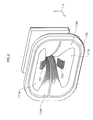
- FIG. 1 is a side view of a color picture tube device to which the embodiments of the present invention relate.
- the color picture tube device is roughly made up of an envelope including a panel 10 and a funnel 20, an in-line electron gun 30, and a deflection yoke 100.
- a phosphor screen is formed on the internal face of the panel 10.
- the in-line electron gun 30 is provided in a neck of the funnel 20, and emits three electron beams toward the phosphor screen.
- the deflection yoke 100 is installed around the funnel 20.
- an electron gun that emits three horizontally-aligned electron beams in parallel with each other along the tube axis is used as the electron gun 30, so that the three electron beams are parallel with each other when entering a deflection region.
- the deflection region referred to here is a region where deflection magnetic fields generated by horizontal and vertical deflection coils in the deflection yoke 100 have deflection effects. Also, while the embodiment describes the case where the three electron beams are arranged in the order of B, G, and R from left to right as seen from the phosphor screen side, the invention is not limited to such an order.
- the deflection yoke 100 forms deflection magnetic fields in the funnel 20, to deflect the electron beams emitted from the electron gun 30.
- FIG. 2 is a perspective view showing an example construction of the deflection yoke 100.
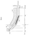
- FIG. 3 is a cross section of the upper half of the deflection yoke 100, cut by a plane that is perpendicular to a horizontal direction (the direction of the X axis) and contains the tube axis (the Z axis).
- the deflection yoke 100 includes a horizontal deflection coil 110, an insulating frame 120, a vertical deflection coil 130, and a ferrite core 140 which are provided in this order in an outward direction (from the inside of the funnel 20 toward the outside).
- the horizontal deflection coil 110 is made up of one pair of horizontal coils 110a and 110b which are each formed by winding a wire in the shape of a saddle.
- the horizontal coils 110a and 110b are set so that their respective windows 111a and 111b provided in the middle face each other, and are positioned along the internal face of the insulating frame 120 so as to be in intimate contact with the insulating frame 120.
- the vertical deflection coil 130 is made up of one pair of vertical coils which are each formed by winding a wire in the shape of a saddle.
- the ferrite core 140 is provided so as to surround these vertical coils.
- the ferrite core 140 serves as a magnetic core or the like, for each of the horizontal deflection coil 110 and the vertical deflection coil 130.
- two coils are provided in the windows 111a and 111b.
- the coil provided in the window 111a is referred to as an upper coil 151
- the coil provided in the window 111b as a lower coil 152.
- the upper coil 151 and the lower coil 152 generate a quadrupole magnetic field through which the three electron beams pass.
- the upper coil 151 and the lower coil 152 are hereafter collectively referred to as a quadrupole magnetic field generation coil.
- the three electron beams are acted upon by such a lens effect that brings the electron beams into convergence on the phosphor screen. This lens effect is explained in detail later.
- each member of the deflection yoke 100 is explained by referring to FIG. 3.
- the position of the phosphor screen end of the quadrupole magnetic field generation coil (the upper coil 151 in FIG. 3) is set as the origin point on the tube axis (the Z axis).
- the origin point is coincided with the position of the deflection center which is called a reference line of the color picture tube device.
- the phosphor screen side is set as the positive direction, while the electron gun side is set as the negative direction.
- the core pieces of the upper coil 151 and lower coil 152 are made of a Ni ferrite, and have a width of 15mm. These core pieces are embedded in the insulating frame 120 in the windows 111a and 111b respectively (though the upper coil 151 and the lower coil 152 are shown to appear in FIG. 2 for convenience in explanation) . Note here that the upper coil 151 and the lower coil 152 do not necessarily need to be embedded in the insulating frame 120, so long as the upper coil 151 and the lower coil 152 are insulated from the horizontal deflection coil 110.
- the quadrupole magnetic field generation coil it is preferable for the quadrupole magnetic field generation coil to be situated between the electron gun end of the ferrite core 140 and the phosphor screen in the direction of the tube axis.
- a horizontal deflection magnetic field generated by the horizontal deflection coil 110 and a vertical deflection magnetic field generated by the vertical deflection coil 130 have their deflection effects substantially in a region which is closer to the phosphor screen than the electron gun end of the ferrite core 140. Therefore, if the quadrupole magnetic field is generated therebetween, the passing positions of the three electron beams in the quadrupole magnetic field change according to the deflection. This allows the three electron beams to be acted upon by an appropriate lens effect according to the deflection.
- a horizontal sawtooth deflection current corresponding to a horizontal deflection frequency is supplied to the horizontal deflection coil 110.
- the horizontal deflection coil 110 generates a magnetic field in the vertical direction in the funnel 20, and deflects the electron beams in the horizontal direction.
- a vertical sawtooth deflection current corresponding to a vertical deflection frequency is supplied to the vertical deflection coil 130.
- the vertical deflection coil 130 generates a magnetic field in the horizontal direction in the funnel 20, and deflects the electron beams in the vertical direction.
- the horizontal deflection magnetic field generated by the horizontal deflection coil 110 and the vertical deflection magnetic field generated by the vertical deflection coil 130 are each a substantially uniform magnetic field.
- a horizontal deflection magnetic field can be regarded as being substantially uniform when the following condition is met.
- the magnetic flux density of the vertical component of the horizontal deflection magnetic field does not vary with a displacement in the horizontal direction, and only varies with a displacement in the direction of the tube axis.
- a vertical deflection magnetic field can be regarded as being substantially uniform when the following condition is met.
- the magnetic flux density of the horizontal component of the vertical deflection magnetic field does not vary with a displacement in the vertical direction, and only varies with a displacement in the direction of the tube axis.
- the use of such substantially uniform magnetic fields as the deflection magnetic fields has the following advantage. Since the deflection magnetic fields which are substantially uniform have almost no distortions, the three electron beams are not acted upon by the lens effects of the deflection magnetic fields. Accordingly, the deformation of the electron beam spot shape does not occur. Hence a high resolution can be achieved.
- the three electron beams are parallel with each other when entering the electron gun end of the deflection region (i.e. the electron gun end of the ferrite core 140 in the deflection yoke 100) in this embodiment.
- the deflection magnetic fields are substantially uniform, and the three electron beams entering the deflection region are parallel with each other.
- the three electron beams arriving at the phosphor screen have almost no mutual deviations in the vertical direction, though they have mutual deviations in the horizontal direction. Therefore, the three electron beams can be brought into convergence if the horizontal deviations are adjusted.
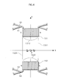
- FIG. 4 shows the upper coil 151, the lower coil 152, and the three electron beams (R, G, B) passing therebetween, as seen from the phosphor screen side.
- the upper coil 151 and the lower coil 152 are each formed by winding two wires on a core piece.
- a quadrupole magnetic field generation wire 40 and an auxiliary magnetic field generation wire 41 are wound together on a core piece.
- a quadrupole magnetic field generation wire 50 and an auxiliary magnetic field generation wire 51 are wound together on a core piece.
- Each wire has the same number of turns, which is 100 in this embodiment.
- the quadrupole magnetic field generation wires 40 and 50 are respectively insulated from the auxiliary magnetic field generation wires 41 and 51.
- a steady-state current is supplied to the quadrupole magnetic field generation wires 40 and 50. Meanwhile, a current synchronous with the vertical deflection current is supplied to the auxiliary magnetic field generation wires 41 and 51.
- FIG. 5 shows the current-carrying states of these wires according to the vertical deflection.
- IDC denotes the current supplied to the quadrupole magnetic field generation wires 40 and 50 of the upper coil 151 and lower coil 152.
- IU denotes the current supplied to the auxiliary magnetic field generation wire 41 of the upper coil 151.
- IB denotes the current supplied to the auxiliary magnetic field generation wire 51 of the lower coil 152.
- a steady-state current is given to each of the wires 40 and 50.
- the value of the steady-state current is positive.
- no current is supplied to the wires 41 and 51.
- a negative current is supplied to the wire 41 while a positive current is supplied to the wire 51, according to the deflection.
- the absolute values of these negative and positive currents increase with the upward deflection.
- the absolute values of the currents of the wires 41 and 51 are largest.
- the vertical deflection frequency is low around several tens of Hz, supplying the currents synchronous with this vertical deflection frequency to the wires 41 and 51 can be done easily, without high power consumption or complex circuit construction.
- the quadrupole magnetic field generation coil substantially acts as a magnet coil which is made up of only the core pieces and the wires 40 and 50, and so generates a quadrupole magnetic field.
- the north pole of the upper coil 151 and the south pole of the lower coil 152 face each other on the right in the horizontal direction whereas the south pole of the upper coil 151 and the north pole of the lower coil 152 face each other on the left in the horizontal direction, as shown in FIG. 4.
- the quadrupole magnetic field has a vertical component 1511 directed from the north pole of the upper coil 151 to the south pole of the lower coil 152 and a vertical component 1521 directed from the north pole of the lower coil 152 to the south pole of the upper coil 151.
- These vertical components 1511 and 1521 exert a force on the electron beams in the horizontal direction.
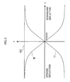
- the vertical components 1511 and 1521 of this quadrupole magnetic field have a magnetic flux density distribution in the horizontal direction shown in FIG. 6.
- X denotes a displacement in the horizontal direction from the tube axis.
- Peaks 1515 and 1525 of the absolute value of the magnetic flux density occur near the magnetic poles, though they do not exactly coincide with the positions of the magnetic poles. The precise peak positions can be changed according to the factors such as the shape of each core piece of the quadrupole magnetic field generation coil (the shape of flowing out of the magnetic flux).
- the three electron beams always pass between these two peaks 1515 and 1525, irrespective of whether they are horizontally deflected or not.
- the passing positions of the three electron beams between the two peaks 1515 and 1525 differ according to the horizontal deflection.
- the three electron beams are horizontally deflected. Since the quadrupole magnetic field is closer to the phosphor screen than the electron gun end of the deflection region, the passing positions of the three electron beams in the quadrupole magnetic field change according to the horizontal deflection. Hence the three electron beams are affected by the quadrupole magnetic field with different intensities.
- the horizontal converging effect acting upon the three electron beams is weaker when compared with the case where the three electron beams are not horizontally deflected.
- the horizontal converging effect of the magnetic lens weakens from the center to the periphery in the horizontal direction.
- the magnetic lens has an intensity distribution such that the horizontal converging effect becomes weaker as the distance from the center increases in the horizontal direction.
- the three electron beams are deflected more in the horizontal direction, they pass through a part of the magnetic lens where the horizontal converging effect is weaker.
- the three electron beams are subjected to a weaker horizontal converging effect in the periphery than in the center in the horizontal direction.
- the three electron beams can be converged at a farther point in the horizontal edges of the phosphor screen, when compared with the center of the phosphor screen. Accordingly, in a color picture tube device in which the distance between the electron gun and the phosphor screen is greater in the horizontal edges than in the center of the phosphor screen, proper convergence can be produced without causing horizontal deviations called "positive XH misconvergence" shown in FIG. 7. Also, since this is achieved by the intensity distribution of the magnetic lens, there is no need to vary the horizontal converging effect of the magnetic lens in sync with the horizontal deflection.
- the vertical component of the resulting magnetic field has a magnetic flux density distribution that is asymmetrical in the horizontal direction with respect to the tube axis, as seen from above the tube axis.
- Such an asymmetrical magnetic flux density distribution delivers the aforementioned lens effect for adjusting convergence.
- This is a distinctive feature of the present invention, when compared with a conventional horizontal deflection magnetic field whose magnetic flux density distribution is symmetrical.
- the magnetic field for adjusting convergence in the present invention is not limited to a quadrupole magnetic field.
- the distance between the electron gun and the phosphor screen is greater in the vertical edges than in the center of the phosphor screen, as in the case of the horizontal direction. To produce proper convergence, therefore, the horizontal converging effect of the quadrupole magnetic field needs to be weakened according to the vertical deflection. However, simply weakening the whole quadrupole magnetic field according to the vertical deflection cannot achieve proper convergence. The reason for this is given below.
- the quadrupole magnetic field shown in FIG. 4 has a horizontal component 1512 generated between the two magnetic poles of the upper coil 151 and a horizontal component 1522 generated between the two magnetic poles of the lower coil 152, in addition to the vertical components 1511 and 1521 between the upper coil 151 and the lower coil 152.
- the electron beams become closer to either the upper coil 151 or the lower coil 152.
- the electron beams are affected by either the horizontal component 1512 or the horizontal component 1522.
- the horizontal component 1512 exerts a force of moving the electron beams upwardly, whilst the horizontal component 1522 exerts a force of moving the electron beams downwardly.
- the three electron beams which are vertically deflected tend to be moved in different directions due to these horizontal components 1512 and 1522.
- unwanted forces such as an additional force of moving the three electron beams closer to each other in the horizontal direction and a force of deviating the three electron beams in the vertical direction, arise according to the vertical direction.
- the three electron beams may meet each other before they reach the phosphor screen (this is called “overconvergence”).
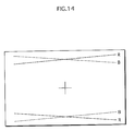
- This causes horizontal misconvergence called “positive YH misconvergence” to occur in the upper and lower portions of the phosphor screen as shown in FIG. 8, or vertical misconvergence called “positive PQV misconvergence” to occur in the corners of the phosphor screen as shown in FIG. 9.
- the present invention provides a technique for suppressing such misconvergence by actively weakening the horizontal components.
- the auxiliary magnetic field generation wires 41 and 51 are wound together with the quadrupole magnetic field generation wires 40 and 50 in the quadrupole magnetic field generation coil. This being so, the currents flowing through the auxiliary magnetic field generation wires 41 and 51 are controlled to weaken the horizontal components of the quadrupole magnetic field. This is explained in detail below.
- the upper coil 151 and the lower coil 152 include the auxiliary magnetic field generation wires 41 and 51 as well as the quadrupole magnetic field generation wires 40 and 50, as shown in FIG. 4.
- a steady-state current is supplied to each of the quadrupole magnetic field generation wires 40 and 50, whereas a current synchronous with the vertical deflection current is supplied to each of the auxiliary magnetic field generation wires 41 and 51.
- a compound magnetic field made up of a virtual sextupole magnetic field designated by the solid arrow and a virtual dipole magnetic field designated by the dashed arrow is generated (such a compound magnetic field is hereafter referred to as a "dipole-sextupole compound auxiliary magnetic field").
- this dipole-sextupole compound auxiliary magnetic field is superposed on the quadrupole magnetic field shown in FIG. 4.
- the currents are supplied to the wires 40, 41, 50, and 51 as shown in FIG. 5.
- the horizontal component 1512 shown in FIG. 4 is weakened according to the vertical deflection.
- the horizontal component 1522 is weakened according to the vertical deflection.
- the vertical components 1511 and 1521 weaken according to the vertical deflection, too.
- the degree of weakness of the vertical components 1511 and 1521 is smaller than that of the horizontal components 1512 and 1522, partly because the amount of current supplied to the wire 51 of the lower coil 152 increases in the case of upward direction, as shown in FIG. 5.
- This embodiment describes the case where a steady-state current is supplied to each of the wires 40 and 50.
- fine adjustments may be made to the current supplied to each of the wires 40 and 50.
- magnets may be employed to generate a magnetic flux corresponding to the magnetic flux generated by the wires 40 and 50. In this case, it is unnecessary to supply the steady-state current IDC shown in FIG. 5.
- wires may be wound on these magnets to make fine adjustments.
- this embodiment describes the case where separate wires are used as the wire 40 of the upper coil 151 and the wire 50 of the lower coil 152, but the same wire may be used if the same steady-state current is supplied.
- the first embodiment describes how to produce convergence in a color picture tube device in which the deflection magnetic fields are substantially uniform and the three electron beams entering the deflection region are parallel with each other.
- the three electron beams will end up being underconverged in the center and edges of the phosphor screen if there is no quadrupole magnetic field.
- the quadrupole magnetic field having the horizontal converging effect is employed to converge the three electron beams.
- the applicable scope of the present invention is not limited to a color picture tube device in which the deflection magnetic fields are substantially uniform and the three electron beams are parallel with each other.
- the present invention is applicable even when the deflection magnetic fields have some distortions or when the three electron beams are not parallel with each other.
- the three electron beams may be overconverged notably in the center of the phosphor screen if there is no quadrupole magnetic field. The following describes a technique for converging the three electron beams in such a case.
- FIG. 12 shows a quadrupole magnetic field of the second embodiment.
- This drawing corresponds to FIG. 4 in the first embodiment.
- the north pole and the south pole of each of the upper coil 151 and the lower coil 152 have been interchanged from the first embodiment.
- vertical components 1513 and 1523 of this quadrupole magnetic field exert a horizontal diverging effect on the three electron beams.
- this horizontal diverging effect weakens according to the horizontal deflection. Therefore, horizontal deviations called "negative XH misconvergence" (see FIG. 13), which occurs when the electron beams are acted upon by a diverging effect in the horizontal edges, can be prevented.
- the three electron beams are brought into proper convergence according to the horizontal deflection.
- an auxiliary magnetic field is superposed on the quadrupole magnetic field so as to reduce the horizontal components of the quadrupole magnetic field according to the vertical deflection, like the first embodiment.
- the orientation of the auxiliary magnetic field needs to be opposite, too.
- adjustments need be made to the numbers of turns of the wires 41 and 51 and the like, in consideration of the differences of the deflection magnetic fields from the first embodiment.
- the method of reducing the horizontal components of the quadrupole magnetic field, including the current-carrying states of the wires shown in FIG. 5, is similar to that of the first embodiment so long as modifications are made to reverse the direction of the magnetic flux of the first embodiment. Therefore, its detailed explanation has been omitted here.
- the first and second embodiments describe the case where a quadrupole magnetic field generation wire and an auxiliary magnetic field generation wire are wound on the same core piece, but the method of generating the auxiliary magnetic field is not limited to such.
- a saddle coil may be provided in the vicinity of the vertical deflection coil of the deflection yoke.
- a troidal coil may be provided in the vicinity of the vertical deflection coil.
- the auxiliary magnetic field generation wires 41 and 51 are respectively wound together with the quadrupole magnetic field generation wires 40 and 50 of the upper coil 151 and lower coil 152.
- the amount of current supplied to each of the auxiliary magnetic field generation wires is varied to cancel out the horizontal components of the quadrupole magnetic field in sync with the vertical deflection.
- the horizontal components of the quadrupole magnetic field are suppressed by varying the amount of current supplied to each of the quadrupole magnetic field generation wires themselves. This is explained in detail below.
- FIG. 15 shows a construction of a quadrupole magnetic field generation coil and an effect of a quadrupole magnetic field in the third embodiment.
- the three electron beams passing between the upper coil 151 and the lower coil 152 are seen from the phosphor screen side.
- the upper coil 151 and the lower coil 152 have quadrupole magnetic field generation wires 42 and 52, and do not have auxiliary magnetic field generation wires.
- FIG. 16 shows the current-carrying states of the wire 42 of the upper coil 151 and the wire 52 of the lower coil 152.
- the vertical axis shows coil current
- the horizontal axis shows vertical deflection.
- the center of the horizontal axis corresponds to when the three electron beams are not vertically deflected.
- the left of the horizontal axis corresponds to when the three electron beams are upwardly deflected.
- the right of the horizontal axis corresponds to when the three electron beams are downwardly deflected.
- IU denotes the current supplied to the wire 42 of the upper coil 151
- IB denotes the current supplied to the wire 52 of the lower coil 152.
- the current supplied to the upper coil 151 decreases as the electron beams are more upwardly deflected, so as to weaken a horizontal component 1517 of the quadrupole magnetic field according to the vertical deflection.
- the horizontal component 1517 is smallest.
- the current supplied to the lower coil 152 decreases as the three electron beams are more downwardly deflected, so as to weaken a horizontal component 1527 of the quadrupole magnetic field according to the vertical deflection.
- the horizontal component 1527 is smallest.
- the current supplied to the lower coil 152 increases when the three electron beams are more upwardly deflected, whilst the current supplied to the upper coil 151 increases when the three electron beams are more downwardly deflected. Accordingly, the degree of weakness of vertical components 1516 and 1526 of the quadrupole magnetic field according to the vertical deflection is smaller than that of the horizontal components 1517 and 1527.
- FIG. 20A is a diagrammatic sketch of the auxiliary magnetic field of the first embodiment (see FIG. 11).
- FIG. 20B is a diagrammatic sketch of a substantially uniform magnetic field as one example of the vertical deflection magnetic field (in the case of upward deflection).
- a compound magnetic field made up of these two magnetic fields is like the one shown in FIG. 20C. Accordingly, the effects of the present invention can be obtained if the vertical deflection magnetic field is changed to the magnetic field shown in FIG. 20C.
- the inventors of the present invention reached the following understanding.
- the vertical deflection magnetic field can be changed into the compound magnetic field shown in FIG. 20C.
- a magnetizable member 157 may be made of a permalloy or the like.
- Such a magnetizable member absorbs magnetic lines of force of the vertical deflection magnetic field. Accordingly, the magnetizable member reduces the magnetic flux density near the passing positions of the electron beams, when the electron beams are vertically deflected. This is equivalent to that the vertical deflection magnetic field is changed to the compound magnetic field of FIG. 20C made up of the vertical deflection magnetic field and the auxiliary magnetic field.
- the factors such as the material, position, and size of the magnetizable member in order to achieve substantially the same effects as the auxiliary magnetic field.
- This optimization can be made based on the magnetic flux density measured using a gauss meter, or through simulation. A specific example of using such a magnetizable member is given below.
- FIG. 21 illustrates an example where the magnetizable member is used.
- the magnet 156 has a horizontal width of 15mm, and a thickness of 1.5mm in the direction of the Y axis.
- the magnetizable member 157 has a horizontal width of 20mm, and a thickness of 1.5mm in the direction of the Y axis.
- the magnet 156 and the magnetizable member 157 are insulated from the horizontal deflection coil 110 by the insulating frame 120, as in the above embodiments.
- the size and the like of the magnetizable member 157 are adjusted based on the magnetic flux density of the deflection magnetic field measured using a gauss meter, so that the magnetic flux density distribution when the magnetizable member 157 is provided is substantially the same as when the auxiliary magnetic field is used.
- the same effects as the above embodiments were confirmed by this construction.
- the vertical deflection magnetic field is substantially uniform in FIG. 20, the vertical deflection magnetic field is not limited to a substantially uniform magnetic field. Even when the vertical deflection magnetic field is a barrel magnetic field, the effects of the present invention can be achieved by adjusting the size and the like of the magnetizable member.
Landscapes
- Video Image Reproduction Devices For Color Tv Systems (AREA)
Applications Claiming Priority (4)
| Application Number | Priority Date | Filing Date | Title |
|---|---|---|---|
| JP2001325693 | 2001-10-23 | ||
| JP2001325693 | 2001-10-23 | ||
| JP2002174928 | 2002-06-14 | ||
| JP2002174928 | 2002-06-14 |
Publications (2)
| Publication Number | Publication Date |
|---|---|
| EP1306876A2 true EP1306876A2 (fr) | 2003-05-02 |
| EP1306876A3 EP1306876A3 (fr) | 2007-09-26 |
Family
ID=26624061
Family Applications (1)
| Application Number | Title | Priority Date | Filing Date |
|---|---|---|---|
| EP02257322A Withdrawn EP1306876A3 (fr) | 2001-10-23 | 2002-10-22 | Tube image couleur |
Country Status (4)
| Country | Link |
|---|---|
| US (1) | US6924589B2 (fr) |
| EP (1) | EP1306876A3 (fr) |
| KR (1) | KR20030033989A (fr) |
| CN (1) | CN1417838A (fr) |
Families Citing this family (1)
| Publication number | Priority date | Publication date | Assignee | Title |
|---|---|---|---|---|
| WO2007124128A2 (fr) * | 2006-04-20 | 2007-11-01 | Liquidia Technologies, Inc. | Dispositifs biologiques de régularisation du débit sanguin et procédés associés |
Family Cites Families (11)
| Publication number | Priority date | Publication date | Assignee | Title |
|---|---|---|---|---|
| US35548A (en) * | 1862-06-10 | Improvement in repeating fire-arms | ||
| US4231009A (en) * | 1978-08-30 | 1980-10-28 | Rca Corporation | Deflection yoke with a magnet for reducing sensitivity of convergence to yoke position |
| US4988926A (en) | 1989-02-08 | 1991-01-29 | U.S. Philips Corporation | Color cathode ray tube system with reduced spot growth |
| DE69020478T2 (de) | 1989-10-02 | 1996-02-22 | Philips Electronics Nv | Farbbildröhrensystem mit reduziertem Fleckwachstum. |
| US5327051A (en) * | 1990-07-19 | 1994-07-05 | Rca Thomson Licensing Corporation | Deflection system with a pair of quadrupole arrangements |
| ATE141713T1 (de) * | 1991-04-02 | 1996-09-15 | Philips Electronics Nv | Farbbildröhre mit verringertem fleckwachstum |
| JPH0950772A (ja) * | 1995-06-01 | 1997-02-18 | Mitsubishi Electric Corp | カラーcrt |
| JPH11509970A (ja) * | 1996-05-21 | 1999-08-31 | フィリップス エレクトロニクス ネムローゼ フェンノートシャップ | ランディング角に影響する素子を有するカラー表示装置 |
| EP1231625A4 (fr) * | 1998-11-10 | 2006-08-23 | Matsushita Electric Industrial Co Ltd | Collet de deviation et tube cathodique couleurs comprenant ledit collet de deviation |
| JP2001043815A (ja) | 1998-12-16 | 2001-02-16 | Toshiba Corp | カラー陰極線管装置 |
| JP3861595B2 (ja) * | 1999-12-22 | 2006-12-20 | 松下電器産業株式会社 | カラー受像管装置 |
-
2002
- 2002-10-18 US US10/273,625 patent/US6924589B2/en not_active Expired - Fee Related
- 2002-10-22 EP EP02257322A patent/EP1306876A3/fr not_active Withdrawn
- 2002-10-23 CN CN02155846A patent/CN1417838A/zh active Pending
- 2002-10-23 KR KR1020020064790A patent/KR20030033989A/ko not_active Withdrawn
Also Published As
| Publication number | Publication date |
|---|---|
| EP1306876A3 (fr) | 2007-09-26 |
| CN1417838A (zh) | 2003-05-14 |
| US6924589B2 (en) | 2005-08-02 |
| US20030080669A1 (en) | 2003-05-01 |
| KR20030033989A (ko) | 2003-05-01 |
Similar Documents
| Publication | Publication Date | Title |
|---|---|---|
| US6069546A (en) | Saddle shaped deflection winding having a winding space | |
| US6150910A (en) | Deflection yoke with geometry distortion correction | |
| US6924589B2 (en) | Color picture tube device having improved horizontal convergence | |
| CA2157443C (fr) | Collier de deviation et tube cathodique couleur dote de ce collier | |
| US6924590B2 (en) | Color picture tube device with distortion correction coils | |
| US6861793B2 (en) | Color picture tube device with improved horizontal resolution | |
| US6072379A (en) | Saddle shaped deflection winding having winding spaces in the rear | |
| KR20010039960A (ko) | 컨버전스 보정 장치를 가진 컬러 음극선관 | |
| JP2004071529A (ja) | カラー受像管装置 | |
| EP1372182A1 (fr) | Tube image couleur | |
| JP3825212B2 (ja) | カラー受像管装置 | |
| KR100331057B1 (ko) | 보조 코일을 갖는 브라운관용 편향요크 및 그 보조 코일의제작방법 | |
| JP2004071546A (ja) | カラー受像管装置 | |
| EP1641019A1 (fr) | Tube à image couleur | |
| JP2003297261A (ja) | カラー受像管装置 | |
| JP2000195439A (ja) | カラー受像管装置 | |
| JP2004171791A (ja) | カラー受像管装置 | |
| KR20030071319A (ko) | 브라운관용 편향요크 | |
| KR20050011261A (ko) | 음극선관용 편향요 크 | |
| KR20030072887A (ko) | 음극선관용 편향요크 | |
| JP2006100256A (ja) | カラー受像管装置 | |
| KR20040073077A (ko) | 칼라 음극선관 | |
| MXPA99005757A (en) | A saddle shaped deflection winding having a winding space | |
| JP2000173506A (ja) | カラー受像管装置 | |
| JP2001351546A (ja) | カラー受像管装置 |
Legal Events
| Date | Code | Title | Description |
|---|---|---|---|
| PUAI | Public reference made under article 153(3) epc to a published international application that has entered the european phase |
Free format text: ORIGINAL CODE: 0009012 |
|
| AK | Designated contracting states |
Designated state(s): AT BE BG CH CY CZ DE DK EE ES FI FR GB GR IE IT LI LU MC NL PT SE SK TR |
|
| AX | Request for extension of the european patent |
Extension state: AL LT LV MK RO SI |
|
| PUAL | Search report despatched |
Free format text: ORIGINAL CODE: 0009013 |
|
| AK | Designated contracting states |
Kind code of ref document: A3 Designated state(s): AT BE BG CH CY CZ DE DK EE ES FI FR GB GR IE IT LI LU MC NL PT SE SK TR |
|
| AX | Request for extension of the european patent |
Extension state: AL LT LV MK RO SI |
|
| AKX | Designation fees paid | ||
| REG | Reference to a national code |
Ref country code: DE Ref legal event code: 8566 |
|
| STAA | Information on the status of an ep patent application or granted ep patent |
Free format text: STATUS: THE APPLICATION IS DEEMED TO BE WITHDRAWN |
|
| 18D | Application deemed to be withdrawn |
Effective date: 20080327 |