EP1307331B1 - Verbundmaterial mit polymermatrix - Google Patents
Verbundmaterial mit polymermatrix Download PDFInfo
- Publication number
- EP1307331B1 EP1307331B1 EP01975709A EP01975709A EP1307331B1 EP 1307331 B1 EP1307331 B1 EP 1307331B1 EP 01975709 A EP01975709 A EP 01975709A EP 01975709 A EP01975709 A EP 01975709A EP 1307331 B1 EP1307331 B1 EP 1307331B1
- Authority
- EP
- European Patent Office
- Prior art keywords
- fiber
- fibers
- polymer
- die
- mixture
- Prior art date
- Legal status (The legal status is an assumption and is not a legal conclusion. Google has not performed a legal analysis and makes no representation as to the accuracy of the status listed.)
- Expired - Lifetime
Links
- 239000011160 polymer matrix composite Substances 0.000 title description 17
- 229920013657 polymer matrix composite Polymers 0.000 title description 17
- 239000002131 composite material Substances 0.000 claims abstract description 60
- 229920000642 polymer Polymers 0.000 claims abstract description 51
- 239000000203 mixture Substances 0.000 claims abstract description 34
- 239000011159 matrix material Substances 0.000 claims abstract description 18
- 229920002430 Fibre-reinforced plastic Polymers 0.000 claims abstract description 4
- 239000011151 fibre-reinforced plastic Substances 0.000 claims abstract description 4
- 238000000034 method Methods 0.000 claims description 45
- 230000008569 process Effects 0.000 claims description 33
- 239000002134 carbon nanofiber Substances 0.000 claims description 31
- 239000012783 reinforcing fiber Substances 0.000 claims description 26
- 230000037361 pathway Effects 0.000 claims description 9
- 108010007387 therin Proteins 0.000 claims 1
- 239000000835 fiber Substances 0.000 abstract description 128
- 229920000049 Carbon (fiber) Polymers 0.000 description 27
- 239000004917 carbon fiber Substances 0.000 description 27
- 238000001125 extrusion Methods 0.000 description 21
- 238000002441 X-ray diffraction Methods 0.000 description 11
- 238000012360 testing method Methods 0.000 description 11
- -1 polyethylene Polymers 0.000 description 10
- OKTJSMMVPCPJKN-UHFFFAOYSA-N Carbon Chemical compound [C] OKTJSMMVPCPJKN-UHFFFAOYSA-N 0.000 description 9
- 239000004743 Polypropylene Substances 0.000 description 9
- 229920002239 polyacrylonitrile Polymers 0.000 description 9
- 229920001155 polypropylene Polymers 0.000 description 9
- 239000000047 product Substances 0.000 description 9
- VNWKTOKETHGBQD-UHFFFAOYSA-N methane Chemical compound C VNWKTOKETHGBQD-UHFFFAOYSA-N 0.000 description 8
- 229910052799 carbon Inorganic materials 0.000 description 7
- 230000000694 effects Effects 0.000 description 7
- 230000002787 reinforcement Effects 0.000 description 7
- 238000005259 measurement Methods 0.000 description 6
- 229920002959 polymer blend Polymers 0.000 description 6
- 238000013459 approach Methods 0.000 description 5
- 238000001816 cooling Methods 0.000 description 4
- 229920005989 resin Polymers 0.000 description 4
- 239000011347 resin Substances 0.000 description 4
- 239000004020 conductor Substances 0.000 description 3
- 238000005520 cutting process Methods 0.000 description 3
- 230000009969 flowable effect Effects 0.000 description 3
- 239000003365 glass fiber Substances 0.000 description 3
- 239000008240 homogeneous mixture Substances 0.000 description 3
- 239000000463 material Substances 0.000 description 3
- 238000002156 mixing Methods 0.000 description 3
- 239000003973 paint Substances 0.000 description 3
- 239000000523 sample Substances 0.000 description 3
- 239000004698 Polyethylene Substances 0.000 description 2
- 230000015556 catabolic process Effects 0.000 description 2
- 239000013078 crystal Substances 0.000 description 2
- 238000006731 degradation reaction Methods 0.000 description 2
- 238000013461 design Methods 0.000 description 2
- 238000001035 drying Methods 0.000 description 2
- 239000000446 fuel Substances 0.000 description 2
- 239000011521 glass Substances 0.000 description 2
- 229910021389 graphene Inorganic materials 0.000 description 2
- 238000010438 heat treatment Methods 0.000 description 2
- 229930195733 hydrocarbon Natural products 0.000 description 2
- 150000002430 hydrocarbons Chemical class 0.000 description 2
- 239000004615 ingredient Substances 0.000 description 2
- 238000003754 machining Methods 0.000 description 2
- 238000004519 manufacturing process Methods 0.000 description 2
- 229910052751 metal Inorganic materials 0.000 description 2
- 239000002184 metal Substances 0.000 description 2
- 238000012986 modification Methods 0.000 description 2
- 230000004048 modification Effects 0.000 description 2
- 238000000465 moulding Methods 0.000 description 2
- 229920001778 nylon Polymers 0.000 description 2
- 229920000573 polyethylene Polymers 0.000 description 2
- 229920005629 polypropylene homopolymer Polymers 0.000 description 2
- 238000012545 processing Methods 0.000 description 2
- 230000035939 shock Effects 0.000 description 2
- 239000007787 solid Substances 0.000 description 2
- 238000009864 tensile test Methods 0.000 description 2
- 238000010257 thawing Methods 0.000 description 2
- 229920001169 thermoplastic Polymers 0.000 description 2
- 239000003039 volatile agent Substances 0.000 description 2
- SMZOUWXMTYCWNB-UHFFFAOYSA-N 2-(2-methoxy-5-methylphenyl)ethanamine Chemical compound COC1=CC=C(C)C=C1CCN SMZOUWXMTYCWNB-UHFFFAOYSA-N 0.000 description 1
- ZOXJGFHDIHLPTG-UHFFFAOYSA-N Boron Chemical compound [B] ZOXJGFHDIHLPTG-UHFFFAOYSA-N 0.000 description 1
- 239000004215 Carbon black (E152) Substances 0.000 description 1
- CERQOIWHTDAKMF-UHFFFAOYSA-N Methacrylic acid Chemical compound CC(=C)C(O)=O CERQOIWHTDAKMF-UHFFFAOYSA-N 0.000 description 1
- 239000004677 Nylon Substances 0.000 description 1
- BQCADISMDOOEFD-UHFFFAOYSA-N Silver Chemical compound [Ag] BQCADISMDOOEFD-UHFFFAOYSA-N 0.000 description 1
- 238000005162 X-ray Laue diffraction Methods 0.000 description 1
- 238000005299 abrasion Methods 0.000 description 1
- 230000009471 action Effects 0.000 description 1
- 230000001154 acute effect Effects 0.000 description 1
- 150000001408 amides Chemical class 0.000 description 1
- 238000004458 analytical method Methods 0.000 description 1
- 239000004760 aramid Substances 0.000 description 1
- 229920003235 aromatic polyamide Polymers 0.000 description 1
- 230000004888 barrier function Effects 0.000 description 1
- 230000005540 biological transmission Effects 0.000 description 1
- 229910052796 boron Inorganic materials 0.000 description 1
- 239000007795 chemical reaction product Substances 0.000 description 1
- 239000003795 chemical substances by application Substances 0.000 description 1
- 230000001427 coherent effect Effects 0.000 description 1
- 230000006835 compression Effects 0.000 description 1
- 238000007906 compression Methods 0.000 description 1
- 238000007796 conventional method Methods 0.000 description 1
- 239000002826 coolant Substances 0.000 description 1
- 229920001577 copolymer Polymers 0.000 description 1
- 238000002425 crystallisation Methods 0.000 description 1
- 230000008025 crystallization Effects 0.000 description 1
- 230000001419 dependent effect Effects 0.000 description 1
- 238000005137 deposition process Methods 0.000 description 1
- 230000001627 detrimental effect Effects 0.000 description 1
- 238000010586 diagram Methods 0.000 description 1
- 239000006185 dispersion Substances 0.000 description 1
- 238000009826 distribution Methods 0.000 description 1
- 150000002118 epoxides Chemical class 0.000 description 1
- 150000002148 esters Chemical class 0.000 description 1
- 229920006379 extruded polypropylene Polymers 0.000 description 1
- 230000004927 fusion Effects 0.000 description 1
- 238000011835 investigation Methods 0.000 description 1
- 239000007788 liquid Substances 0.000 description 1
- 239000012764 mineral filler Substances 0.000 description 1
- 239000000178 monomer Substances 0.000 description 1
- 239000002071 nanotube Substances 0.000 description 1
- 238000010422 painting Methods 0.000 description 1
- 239000002245 particle Substances 0.000 description 1
- 239000004417 polycarbonate Substances 0.000 description 1
- 229920000515 polycarbonate Polymers 0.000 description 1
- 229920000728 polyester Polymers 0.000 description 1
- 239000002861 polymer material Substances 0.000 description 1
- 238000006116 polymerization reaction Methods 0.000 description 1
- 229920000098 polyolefin Polymers 0.000 description 1
- 229920002635 polyurethane Polymers 0.000 description 1
- 239000004814 polyurethane Substances 0.000 description 1
- 239000011118 polyvinyl acetate Substances 0.000 description 1
- 229920002689 polyvinyl acetate Polymers 0.000 description 1
- 229920002451 polyvinyl alcohol Polymers 0.000 description 1
- 235000019422 polyvinyl alcohol Nutrition 0.000 description 1
- 239000004800 polyvinyl chloride Substances 0.000 description 1
- 229920000915 polyvinyl chloride Polymers 0.000 description 1
- 239000002243 precursor Substances 0.000 description 1
- 238000002360 preparation method Methods 0.000 description 1
- 230000000750 progressive effect Effects 0.000 description 1
- 238000000197 pyrolysis Methods 0.000 description 1
- 230000005855 radiation Effects 0.000 description 1
- 239000011208 reinforced composite material Substances 0.000 description 1
- HBMJWWWQQXIZIP-UHFFFAOYSA-N silicon carbide Chemical compound [Si+]#[C-] HBMJWWWQQXIZIP-UHFFFAOYSA-N 0.000 description 1
- 229910010271 silicon carbide Inorganic materials 0.000 description 1
- 229910052709 silver Inorganic materials 0.000 description 1
- 239000004332 silver Substances 0.000 description 1
- 238000007711 solidification Methods 0.000 description 1
- 230000008023 solidification Effects 0.000 description 1
- 239000002904 solvent Substances 0.000 description 1
- 239000000126 substance Substances 0.000 description 1
- 230000005469 synchrotron radiation Effects 0.000 description 1
- 229920005992 thermoplastic resin Polymers 0.000 description 1
- 229920001187 thermosetting polymer Polymers 0.000 description 1
- 239000004416 thermosoftening plastic Substances 0.000 description 1
- 238000012546 transfer Methods 0.000 description 1
- 238000001291 vacuum drying Methods 0.000 description 1
- 238000007740 vapor deposition Methods 0.000 description 1
- 125000000391 vinyl group Chemical group [H]C([*])=C([H])[H] 0.000 description 1
- 229920002554 vinyl polymer Polymers 0.000 description 1
- 239000011800 void material Substances 0.000 description 1
Images


Classifications
-
- H—ELECTRICITY
- H01—ELECTRIC ELEMENTS
- H01B—CABLES; CONDUCTORS; INSULATORS; SELECTION OF MATERIALS FOR THEIR CONDUCTIVE, INSULATING OR DIELECTRIC PROPERTIES
- H01B1/00—Conductors or conductive bodies characterised by the conductive materials; Selection of materials as conductors
- H01B1/20—Conductive material dispersed in non-conductive organic material
- H01B1/24—Conductive material dispersed in non-conductive organic material the conductive material comprising carbon-silicon compounds, carbon or silicon
-
- B—PERFORMING OPERATIONS; TRANSPORTING
- B29—WORKING OF PLASTICS; WORKING OF SUBSTANCES IN A PLASTIC STATE IN GENERAL
- B29C—SHAPING OR JOINING OF PLASTICS; SHAPING OF MATERIAL IN A PLASTIC STATE, NOT OTHERWISE PROVIDED FOR; AFTER-TREATMENT OF THE SHAPED PRODUCTS, e.g. REPAIRING
- B29C48/00—Extrusion moulding, i.e. expressing the moulding material through a die or nozzle which imparts the desired form; Apparatus therefor
- B29C48/022—Extrusion moulding, i.e. expressing the moulding material through a die or nozzle which imparts the desired form; Apparatus therefor characterised by the choice of material
-
- B—PERFORMING OPERATIONS; TRANSPORTING
- B29—WORKING OF PLASTICS; WORKING OF SUBSTANCES IN A PLASTIC STATE IN GENERAL
- B29C—SHAPING OR JOINING OF PLASTICS; SHAPING OF MATERIAL IN A PLASTIC STATE, NOT OTHERWISE PROVIDED FOR; AFTER-TREATMENT OF THE SHAPED PRODUCTS, e.g. REPAIRING
- B29C48/00—Extrusion moulding, i.e. expressing the moulding material through a die or nozzle which imparts the desired form; Apparatus therefor
- B29C48/03—Extrusion moulding, i.e. expressing the moulding material through a die or nozzle which imparts the desired form; Apparatus therefor characterised by the shape of the extruded material at extrusion
- B29C48/07—Flat, e.g. panels
- B29C48/08—Flat, e.g. panels flexible, e.g. films
-
- B—PERFORMING OPERATIONS; TRANSPORTING
- B29—WORKING OF PLASTICS; WORKING OF SUBSTANCES IN A PLASTIC STATE IN GENERAL
- B29C—SHAPING OR JOINING OF PLASTICS; SHAPING OF MATERIAL IN A PLASTIC STATE, NOT OTHERWISE PROVIDED FOR; AFTER-TREATMENT OF THE SHAPED PRODUCTS, e.g. REPAIRING
- B29C70/00—Shaping composites, i.e. plastics material comprising reinforcements, fillers or preformed parts, e.g. inserts
- B29C70/04—Shaping composites, i.e. plastics material comprising reinforcements, fillers or preformed parts, e.g. inserts comprising reinforcements only, e.g. self-reinforcing plastics
- B29C70/06—Fibrous reinforcements only
- B29C70/10—Fibrous reinforcements only characterised by the structure of fibrous reinforcements, e.g. hollow fibres
- B29C70/12—Fibrous reinforcements only characterised by the structure of fibrous reinforcements, e.g. hollow fibres using fibres of short length, e.g. in the form of a mat
- B29C70/14—Fibrous reinforcements only characterised by the structure of fibrous reinforcements, e.g. hollow fibres using fibres of short length, e.g. in the form of a mat oriented
-
- H—ELECTRICITY
- H01—ELECTRIC ELEMENTS
- H01M—PROCESSES OR MEANS, e.g. BATTERIES, FOR THE DIRECT CONVERSION OF CHEMICAL ENERGY INTO ELECTRICAL ENERGY
- H01M4/00—Electrodes
- H01M4/02—Electrodes composed of, or comprising, active material
- H01M4/13—Electrodes for accumulators with non-aqueous electrolyte, e.g. for lithium-accumulators; Processes of manufacture thereof
- H01M4/137—Electrodes based on electro-active polymers
-
- H—ELECTRICITY
- H01—ELECTRIC ELEMENTS
- H01M—PROCESSES OR MEANS, e.g. BATTERIES, FOR THE DIRECT CONVERSION OF CHEMICAL ENERGY INTO ELECTRICAL ENERGY
- H01M4/00—Electrodes
- H01M4/02—Electrodes composed of, or comprising, active material
- H01M4/36—Selection of substances as active materials, active masses, active liquids
- H01M4/362—Composites
- H01M4/364—Composites as mixtures
-
- H—ELECTRICITY
- H01—ELECTRIC ELEMENTS
- H01M—PROCESSES OR MEANS, e.g. BATTERIES, FOR THE DIRECT CONVERSION OF CHEMICAL ENERGY INTO ELECTRICAL ENERGY
- H01M4/00—Electrodes
- H01M4/02—Electrodes composed of, or comprising, active material
- H01M4/36—Selection of substances as active materials, active masses, active liquids
- H01M4/60—Selection of substances as active materials, active masses, active liquids of organic compounds
- H01M4/602—Polymers
-
- H—ELECTRICITY
- H01—ELECTRIC ELEMENTS
- H01M—PROCESSES OR MEANS, e.g. BATTERIES, FOR THE DIRECT CONVERSION OF CHEMICAL ENERGY INTO ELECTRICAL ENERGY
- H01M4/00—Electrodes
- H01M4/86—Inert electrodes with catalytic activity, e.g. for fuel cells
- H01M4/88—Processes of manufacture
- H01M4/8825—Methods for deposition of the catalytic active composition
- H01M4/8864—Extrusion
-
- H—ELECTRICITY
- H01—ELECTRIC ELEMENTS
- H01M—PROCESSES OR MEANS, e.g. BATTERIES, FOR THE DIRECT CONVERSION OF CHEMICAL ENERGY INTO ELECTRICAL ENERGY
- H01M4/00—Electrodes
- H01M4/86—Inert electrodes with catalytic activity, e.g. for fuel cells
- H01M4/88—Processes of manufacture
- H01M4/8875—Methods for shaping the electrode into free-standing bodies, like sheets, films or grids, e.g. moulding, hot-pressing, casting without support, extrusion without support
-
- H—ELECTRICITY
- H01—ELECTRIC ELEMENTS
- H01M—PROCESSES OR MEANS, e.g. BATTERIES, FOR THE DIRECT CONVERSION OF CHEMICAL ENERGY INTO ELECTRICAL ENERGY
- H01M4/00—Electrodes
- H01M4/86—Inert electrodes with catalytic activity, e.g. for fuel cells
- H01M4/96—Carbon-based electrodes
-
- B—PERFORMING OPERATIONS; TRANSPORTING
- B29—WORKING OF PLASTICS; WORKING OF SUBSTANCES IN A PLASTIC STATE IN GENERAL
- B29K—INDEXING SCHEME ASSOCIATED WITH SUBCLASSES B29B, B29C OR B29D, RELATING TO MOULDING MATERIALS OR TO MATERIALS FOR MOULDS, REINFORCEMENTS, FILLERS OR PREFORMED PARTS, e.g. INSERTS
- B29K2105/00—Condition, form or state of moulded material or of the material to be shaped
- B29K2105/06—Condition, form or state of moulded material or of the material to be shaped containing reinforcements, fillers or inserts
- B29K2105/12—Condition, form or state of moulded material or of the material to be shaped containing reinforcements, fillers or inserts of short lengths, e.g. chopped filaments, staple fibres or bristles
- B29K2105/14—Condition, form or state of moulded material or of the material to be shaped containing reinforcements, fillers or inserts of short lengths, e.g. chopped filaments, staple fibres or bristles oriented
-
- B—PERFORMING OPERATIONS; TRANSPORTING
- B29—WORKING OF PLASTICS; WORKING OF SUBSTANCES IN A PLASTIC STATE IN GENERAL
- B29K—INDEXING SCHEME ASSOCIATED WITH SUBCLASSES B29B, B29C OR B29D, RELATING TO MOULDING MATERIALS OR TO MATERIALS FOR MOULDS, REINFORCEMENTS, FILLERS OR PREFORMED PARTS, e.g. INSERTS
- B29K2301/00—Use of unspecified macromolecular compounds as reinforcement
- B29K2301/10—Thermosetting resins
-
- H—ELECTRICITY
- H01—ELECTRIC ELEMENTS
- H01M—PROCESSES OR MEANS, e.g. BATTERIES, FOR THE DIRECT CONVERSION OF CHEMICAL ENERGY INTO ELECTRICAL ENERGY
- H01M4/00—Electrodes
- H01M4/02—Electrodes composed of, or comprising, active material
- H01M4/62—Selection of inactive substances as ingredients for active masses, e.g. binders, fillers
- H01M4/624—Electric conductive fillers
- H01M4/625—Carbon or graphite
-
- H—ELECTRICITY
- H01—ELECTRIC ELEMENTS
- H01M—PROCESSES OR MEANS, e.g. BATTERIES, FOR THE DIRECT CONVERSION OF CHEMICAL ENERGY INTO ELECTRICAL ENERGY
- H01M4/00—Electrodes
- H01M4/02—Electrodes composed of, or comprising, active material
- H01M4/64—Carriers or collectors
-
- H—ELECTRICITY
- H01—ELECTRIC ELEMENTS
- H01M—PROCESSES OR MEANS, e.g. BATTERIES, FOR THE DIRECT CONVERSION OF CHEMICAL ENERGY INTO ELECTRICAL ENERGY
- H01M4/00—Electrodes
- H01M4/86—Inert electrodes with catalytic activity, e.g. for fuel cells
- H01M4/8647—Inert electrodes with catalytic activity, e.g. for fuel cells consisting of more than one material, e.g. consisting of composites
- H01M4/8652—Inert electrodes with catalytic activity, e.g. for fuel cells consisting of more than one material, e.g. consisting of composites as mixture
-
- Y—GENERAL TAGGING OF NEW TECHNOLOGICAL DEVELOPMENTS; GENERAL TAGGING OF CROSS-SECTIONAL TECHNOLOGIES SPANNING OVER SEVERAL SECTIONS OF THE IPC; TECHNICAL SUBJECTS COVERED BY FORMER USPC CROSS-REFERENCE ART COLLECTIONS [XRACs] AND DIGESTS
- Y02—TECHNOLOGIES OR APPLICATIONS FOR MITIGATION OR ADAPTATION AGAINST CLIMATE CHANGE
- Y02E—REDUCTION OF GREENHOUSE GAS [GHG] EMISSIONS, RELATED TO ENERGY GENERATION, TRANSMISSION OR DISTRIBUTION
- Y02E60/00—Enabling technologies; Technologies with a potential or indirect contribution to GHG emissions mitigation
- Y02E60/10—Energy storage using batteries
-
- Y—GENERAL TAGGING OF NEW TECHNOLOGICAL DEVELOPMENTS; GENERAL TAGGING OF CROSS-SECTIONAL TECHNOLOGIES SPANNING OVER SEVERAL SECTIONS OF THE IPC; TECHNICAL SUBJECTS COVERED BY FORMER USPC CROSS-REFERENCE ART COLLECTIONS [XRACs] AND DIGESTS
- Y02—TECHNOLOGIES OR APPLICATIONS FOR MITIGATION OR ADAPTATION AGAINST CLIMATE CHANGE
- Y02E—REDUCTION OF GREENHOUSE GAS [GHG] EMISSIONS, RELATED TO ENERGY GENERATION, TRANSMISSION OR DISTRIBUTION
- Y02E60/00—Enabling technologies; Technologies with a potential or indirect contribution to GHG emissions mitigation
- Y02E60/30—Hydrogen technology
- Y02E60/50—Fuel cells
Definitions
- the present invention relates to polymer matrix composites with high strength, high thermal conductivity and high electrical conductivity as well as to processes for making these composites.
- Glass fibers are the most common reinforcing fibers for polymer matrix composites due to their low-cost and high strength. They are commonly referred to as "basic" composites and are used in many high-volume applications, particularly the automotive industry.
- the disadvantages of glass fibers is that they have a relatively low modulus of elasticity and poor abrasion resistance. This results in a decrease in service rating and poor adhesion to polymer matrix resins, especially in the presence of moisture.
- Carbon fibers are currently the most widely used advanced fibers, and are generally manufactured by the pyrolysis of a polyacrylonitrile (PAN), or a pitch precursor. Each process used to produce carbon fibers has distinct advantages and disadvantages in terms of cost and strength properties. PAN derived fibers have excellent properties, making them the most commonly used carbon fiber. Pitch-based fibers are of lower quality and inferior properties, but are currently the lowest-cost carbon fiber on the market. When compared to glass fibers, carbon fibers offer higher strength and modulus, lower density, outstanding thermal and electrical conductivity, but are much higher in cost. The high cost of producing carbon fibers is the principle barrier prohibiting carbon fiber reinforced composites from wider commercial application.
- vapor-grown carbon fibers are highly graphitic with superior mechanical properties and have excellent electrical and thermal conductivities. Moreover, because of their relative low cost, they have the potential to replace glass and other reinforcing fibers currently used in cost-sensitive commercial markets.
- vapor-grown carbon fibers become randomly aligned and entangled during production. Accordingly, when used as reinforcements, they enhance composite properties isotropically, i.e. essentially uniformly in all directions. Where it is desired to maximize composite performance anisotropically, for example along a given direction, it is necessary to align the fibers along that direction first.
- the present invention is based on the discovery that very short fibers can be easily oriented in polymer matrix composites by extruding a mixture of the fibers and matrix polymer through a die having a large surface to volume ratio, typically at least about 25.4cm -1 (10 in -1 ) and more normally at least about 127 cm -1 (50 in -1 ).
- the present invention provides a process comprising extruding a mixture of short reinforcing fiber and polymer through a die having a surface to volume ratio of at least about about 25.4 cm -1 (10 in -1 ) wherein the short reinforcing fiber has a diameter of about I micron or less, a length of 500 microns or less and an aspect ratio of about 10 to 750, thereby producing a fiber-reinforced polymer matrix composite with anisotropic properties arising because of the orientation of the short reinforcing fiber therein.
- the present invention also provides a process for making a shaped polymer article having anisotropic electrical conductivity, the process comprising extruding a mixture of the polymer and vapor-grown carbon fiber through a die having a surface to volume ratio of at least about 25.4 cm -1 (10 in -1 ) wherein the short reinforcing fiber has a diameter of about 1 micron or less, a length of 500 microns or less and an aspect ratio of about 10 to 750, thereby producing multiple strands of extrudate, and bonding the strands together in an essentially parallel relationship to form the shaped articles.
- the die also has a large length to width ratio as it has been further found that this enhances fiber orientation even more.
- fiber-reinforced polymer matrix composite with improved anisotropic properties are made by extruding a mixture of very small reinforcing fibers and the matrix polymer through a die having a large surface to volume ratio, typically at least about 25.4 cm -1 (10 in -1 ).
- the present invention is applicable to very small reinforcing fibers, that is fibers having lengths no greater than about 500 microns. More typically, the reinforcing fibers used in the present invention will have average lengths no greater than about 200 microns or even about 100 microns. Average lengths of about 5 to 100 microns are especially suitable.
- the reinforcing fibers used in the present invention will typically have diameters of about 1 micron or less, typically about 0.5 microns or less or even about 0.2 micron or less.
- diameter means the maximum transverse direction of the fiber, as fibers with cross-sectional shapes other than circles are also useful in accordance with the present invention.
- the fibers useful in accordance with the present invention may have an aspect ration (length/diameter) of about 10 to 750, more typically about 40 to 200.
- the fibers useful in accordance with the present invention can be made from a wide variety of different materials including glass, carbon, silicon carbide, other fibrous mineral fillers, polymer materials and the like.
- the fibers are made from carbon, with vapour-grown carbon fibers being especially preferred.
- vapour-grown carbon fibres are made by a vapour deposition process using a hydrocarbon source and typically have diameters on the order of about 0.1 to 0.2 microns and lengths on the order of 50 to 100 microns. In general, these fibers are essentially soot-free and are characterized by having an apparent density of less than 0.02 gram per cubic centimetre. Good results are obtained with vapour grown carbon fibers having diameters of up to 0.5 microns and lengths up to 500 microns.
- Vapor grown carbon fibers are described in the above-noted Tibbetts et al patent, US 5,024,818, the disclosure of which is incorporated herein by reference. They differ significantly from conventional chopper fibers used for composite reinforcement, which are typically at least about 1mm (1/32 inch) long - essentially an order of magnitude larger.
- fibers that are useful in the present investigation include "nonofibers" and "nanotubes".
- This relatively new class if fibers refer to elongated structures having a cross-section or diameter less than I micron. The structures may be either hollow or solid.
- Workd conducted by Kennel et al. indicate that these fibers having higher thermal and electrical conductivity and consequently offer great promise in the polymer matrix composites described herein. See US Patent No. 6,156,256; S. Iijima et al; Nature, Vol. 363, 603 (1993); D.S. Bethune et al., Vol. 363, 605, (1993) and R. Kuriger et al. Proceedings of the 34 th National Heat Transfer Conference, Session 55, (2000), the disclosures of which are incorporated herein by reference.
- any polymer which is known, or which becomes known, as being useful for making polymer matrix composites can be used in carrying out the present invention. Suitable examples are described in the above-noted Tepic patent, US 5,093,050, the disclosure of which is also incorporated herein by reference.
- thermoplastic polymers such as the polyolefins, especially polyethylene and polypropylene; vinyl resins such as polyvinyl chloride, polyvinyl acetate and polyvinyl alcohols, and nylons.
- Thermosetting resins such as polyesters, epoxides, polyurethanes as well as polymers and copolymers of acrylic and methacrylic acid and its esters and amides can also be used.
- the improved polymer matrix composite of the present invention is made by an extrusion process, and accordingly the polymer selected for a particular embodiment must be sufficiently liquid to flow through the extruder.
- Many of the above polymers are thermoplastic and can be rendered flowable through simple heating. Others may require the addition of a solvent, as described in the above-noted Tepic patent. Still others can be rendered flowable by using a dispersion of the polymer in its own monomer, with final stages of polymerization occurring during of after extrusion, as further described in the above-noted Tepic patent.
- Preferred polymers are those that readily wet the fiber surfaces and induce a strong bond between the fiber and polymer.
- a thermoplastic resin with a surface tension less than approximately 45 dynes per centimeter at room temperature (20° C), as these are able to more readily wet the surface of the fiber. See US Patent No. 5,433,906, the disclosure of which is also incorporated herein by reference. Examples of such polymers are polycarbonate, polyethylene, polypropylene and nylon.
- the amount of reinforcing fiber that can be included in the improved polymer matrix composites of the present invention can vary widely, and essentially any amount can be used.
- the fiber/polymer mixture obtained must still be extrudable and capable of solidifying into a coherent extrudate.
- the inventive composites will contain about I to 70 percent fiber by volume, more typically about 2 to 40 vol.% and even more typically about 5 to 25 vol.%.
- a homogeneous mixture of the ingredients to be incorporated in the composites of the present invention will be prepared in advance, i.e. prior to being charged into the extruder.
- these ingredients can be separately supplied to the extruder, or supplied in a non-homogeneous mixture, where the inherent mixing action of the extruder is sufficient to achieve the degree of mixing desired.
- screw extruders may be desirable in some instances as they automatically shear mix the fiber/polymer mixture during processing.
- vapour-grown carbon fibers are to be used as the fibrous reinforcement, it is desirable to insure that moisture and volatiles are eliminated from the system. This can be easily done, for example, by heating the fibers in a moderate vacuum at 300°C for 3 hours before they are mixed with the polymer. If the polymer being used is hygroscopic, the mixture so formed should be dried under typical conditions used for drying that particular polymer.
- improved polymer matrix composites are produced using the very small reinforcing fibers described above by extruding a mixture of the fiber and the matrix polymer through a die having a large surface to volume ratio of at least about 25.4 cm -1 (10 in -1 ).
- surface to volume ratio means, for a given travel path through the due defined by an inlet, an outlet and walls extending between the two, the ratio of the surface area of the travel path walls to the travel path volume.
- the die employed has an area to volume ratio of at least about 25.4 cm -1 (10 in -1 ), preferably at least about 127 cm -1 (50 in -1 ), even more preferably at least about 254 cm -1 (100 in -1 ) or even 508 cm -1 (200 in -1 ).
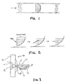
- Figure 1 is a schematic representation of the flow of a polymer/fiber mixture through a cylindrical die.
- the flow has much lower velocity near the walls as compared to the center of the tube. This produces a rate of strain (or a shear) in the flow.
- the flow field is such that the gradient is zero at the center of the flow channel and the highest strain rate (or shear) occurs along the walls.
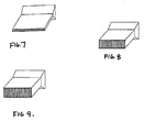
- the fibers suspended in the polymer matrix experience the effects of these velocity differentials, causing the ends of the fibers nearest to the center of the flow channel to move faster than the ends closer to the wall. See Figure 2. This effect will result in progressive rotation of the fiber to bring it in alignment with the flow direction.
- the alignment effect resulting from the use of a die with a large surface to volume ratio can be enhanced even further by subjecting the fiber/polymer mass to the above alignment effect for a longer duration.
- This can be achieved, for example, by extending the length of the die, which produces a longer residence time.
- thd ie also have a lage length to width ratio, i.e. L/W of at least about 6. More preferably, the L/W ratio is 10 or more, or even 20 or more. L/W ratios of 30 or more, or even 40 or more, are contemplated.
- This die generally indicated at 40 includes a converging section 42 for attaching to the barrel of an extruder (not shown) and a shear section 44 attached to the converging section 42.
- Converging section 42 defines a converging channel 46 for receiving a flowable polymer/fiber mixture from the barrel of the extruder and converging it to the smaller flow channel in shear section 44, as further discussed below.
- converging angle a is less than 80°, e.g. about 70° to ⁇ 80°, to produce a converging flow without dead zones and flow reversals that are detrimental to fiber alignment.
- Shear section 44 defines a flow channel or pathway 47 which begins at an inlet 48, terminates at an outlet 50 and is generally defined by walls 52 extending between the inlet and outlet.
- the surface to volume ratio of the die that is the ratio of the area defined by walls 52 to the volume between these walls, extending between inlet 48 and outlet 50, is at least 25.4 cm -1 (10 in -1 ), more typically at least about 127 cm -1 (50 in -1 ) and even more typically at least about 254 cm -1 (100 in -1 ) or even 508 cm -1 (200 in -1 ). This is a far larger ratio than in conventional extruders in which the surface/volume ratio is normally about 12.7 cm -1 (5 in -1 ).
- Figure 6 illustrates a typical extrusion system for carrying out the inventive process.
- extruder 60 charges an extrudable fiber/polymer mixture through die 62.
- die 62 is configured so the flow channel or pathway through the die has a large surface to volume ratio of at least 25.4 cm -1 (10 in -1 ). This causes the fiber/polymer mixture to exit the outlet of the die's flow channel in the form of a strand or ribbon 64.
- Composite processing is initiated by feeding the fiber/polymer mixture, typically in granulated form, into extruder 60.
- a narrow die 62 in accordance with the present invention orientates the fibers suspended in the polymer matrix to produce a continuous, uniform diameter composite strand or ribbon 64 reinforced with aligned very small fibers, preferably vapor-grown carbon fibers.
- the process is continuous and the composite strand is collected and preferably kept in sufficient tension by a material-pulling device 66 until the polymer matrix solidifies.
- the strand exits the die it can be either air-cooled, or processed through a cooling bath. Air-cooling is preferred because it reduces shrinkage voids and crystallization of the polymer matrix.
- the cooling rate of the composite is dependent on many variables such as fiber content, melt-flow temperature, and screw speed.
- puller 66 is provided to draw strand 64 away from die 62 as it solidifies.
- puller 66 can be operated at essentially the same speed as molten fiber/polymer mix exiting die 62. In this case, just enough tension is applied by puller 66 to strand 64 to keep it suspended in air or other cooling medium and moving in its travel path.
- puller 66 can be operated at a faster speed so as to impart significant tension on strand 56, thereby achieving draw down of strand 64 to a narrow diameter.
- draw down is accomplish in an amount of at least 25% in terms of the strand diameter, preferably at least 50%. Since drawing of the strand in this manner will achieve further axial orientation of the fiber, this embodiment achieves still more fiber orientation than operating without draw down.
- the fiber/polymer extrudate produced by the inventive process is in the form of a strand or ribbon, since it is produced in a die having a large surface to volume ratio.
- these strands or ribbons are used to make articles of infinitely varying shape, both simple and complex, with anisotropic properties arranged in any desired manner.
- a shaped article having superior strength, electrical conductivity and/or thermal conductivity across its thickness relative to its length and width can be easily made by laying up multiple strands or ribbons produced by the present invention essentially in parallel and aligned with the thickness direction of the article and then bonding the strands together by fusion bonding, hot compression or other conventional technique.
- a mass of indiscriminate shape such as a block can be made by bonding together multiple, parallel strands or ribbons produced by the inventive process followed by machining this mass into the final shape desired.
- the invention polymer matrix composite is relatively easy to machine, for example by cutting, sawing or the like, articles of complex shape having preferential properties arranged in any desired direction can be easily made in this manner as well.
- This approach is especially suitable for making thin articles such as plates, sheets, webs and the like with preferential properties arranged in the thickness direction, since a large composite mass can be easily built up and then sliced in a direction tranverse to the aligned fiber direction in any desired thickness.
- shaped articles are made following this general approach using extrusion dies having multiple extrusion pathways, each having a large surface to volume ratio of at least 25.4 cm -1 (10 in -1 ), more typically at least about 127 cm -1 (50 in -1 ) and even more typically at least about 254 cm -1 (100 in -1 ) or even 508 cm -1 (200 in -1 ).
- extrusion dies having multiple extrusion pathways, each having a large surface to volume ratio of at least 25.4 cm -1 (10 in -1 ), more typically at least about 127 cm -1 (50 in -1 ) and even more typically at least about 254 cm -1 (100 in -1 ) or even 508 cm -1 (200 in -1 ).
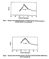
- Examples of such dies are illustrated in Figures 7, 8 and 9.
- each of these dies has multiple extrusion pathways (or in the case of Figure 9 multiple extrusion pathway sections) each of which has a large surface to volume ratio.
- shaped articles made following this general approach and using vapor-grown carbon fibers as the fiber reinforcement exhibit not only excellent electrical conductivities in their aligned fiber directions but also superior tensile strengths as well.
- ultimate tensile strengths of such articles, in their aligned fiber directions are as much as 5 Mpa (725 psi) greater than that of articles otherwise the same but made with conventional carbon fibers instead. This is surprising and enables useful articles to be made from polymer composites with combinations of properties not possible before.
- Polymer matrix composites have already been used for making a wide variety of different commercial products, and the polymer composites of the present invention can also be used for these purposes.
- An especially desirable use for the composites of the present invention is in making shaped articles having preferential electrically conductivity in a predetermined, desired direction.
- Examples of such articles are electrodes, electromagnetic shielding boxes, self defrosting windshield wipers, aircraft defrosting systems, and the like.
- Such articles can be easily made following the principles of the present invention using carbon fibers, especially vapor-grown carbon fibers as the fibrous reinforcement.
- a particularly desirable application of the present invention is in making electrically conductive composites which are thin and/or web-like in form, such as plates or sheets, and whose preferential electrical conductivity is arranged in the thickness direction, or at an acute angle with respect to the thickness direction of the web.
- thin is meant articles whose length and width are at ten time their thickness dimension.
- Preferred thin articles have lengths and widths at least 100 times their thickness dimension.
- Such web-like composites are especially useful in making electrode plates for use in batteries and fuel cells, since they are light weight, strong, vibration and shock resistant and electrically conductive in a direction transverse to their major faces.
- such electrically conductive plates and webs can be easily made by slicing a large composite mass made as described above in a direction transverse to the aligned fiber direction to produce a plate or sheet of the desired thickness.
- Such plates or sheets can be used as is where a separate terminal or other means of electrical connection is unnecessary.
- a current collector can be attached to the plate or sheet in a conventional manner.
- one of the major faces of the plate can be painted with an electrically conductive paint, with one or more wires or other electrical conductors bonded to the paint for collecting current passing through the plate or sheet in its thickness direction.
- a screen or web of metal or other electrically conductive material can be bonded to a major face of an electrically conductive plate of the present invention, or sandwiched between two such electrically conductive plates of the present invention, to serve as a current collector in electrical contact with a terminal or the like. Because the inventive web-like composites easily bond to other materials, as well as being strong, light weight, electrically conductive and resistant to shock and vibrations, electrodes based on such composite/current collector combinations are especially desirable.
- test specimens were formulated containing 1 to 23% volume fraction vapor-grown carbon fiber made in accordance with the above-noted Tibbetts et al. patent, US 5,024,818.
- the fibers had a diameter of about 0.2 micrometers and lengths ranging from 50 to 100 microns and were manufactured by Applied Sciences, Inc., ("ASI") of Cedarville, OH, under the name PR-21-AG. They are essentially soot-free and are characterized by having an apparent density of less than about 0.02 grams per cubic centimeter.
- the fibers were dried in a vacuum oven at approximately 300°C for duration of about 3 hours to assure removal of moisture and volatiles.
- test specimen containing 5% conventional PAN-derived carbon fibers obtained from Mitsubishi Chemical Company and having a diameter of 7 microns and lengths from 2 to 3 mm was also evaluated.
- a constant temperature of 170°C was applied to the narrow die for all the samples.
- the composite mixtures were extruded through two different dies, both dies having a narrow (2 mm diameter) annular flow passageway 47 as illustrated in Figure 3, the surface to volume ratio in both of these dies being 203.2 cm -1 (80 in -1 ).
- one of the dies had a flow passageway 1.25 cm in length, which corresponds to a length/width (L/W) ratio of 6.
- the other die had a flow passageway 6.5 cm long, which corresponds to a L/W ratio of 30.
- the strands so made were then analyzed directly to determine mechanical strength and electrical conductivity.
- anisotropic composite cubes were made from the strands and the thermal conductivity of the cubes so made measured in all three directions. Composite cubes were tested for thermal conductivity because such composite cubes are more representative of actual parts made for real-life industrial applications.
- the composite cubes were made by cutting and placing multiple composite strands in a mold, the strands being arranged unidirectionally with respect to one another. The strands were then hot-pressed into all 3.5719 mm (1/8") thick sheet in an evacuated chamber. The composite sheet so formed has essentially the same degree of fiber alignment as found in the extruded strands.
- the 3.5719 mm (1/8") thick composite sheet was then cut into 25.4 mm (1") by 38.1 mm (1.5”) rectangular pieces. These individual pieces were then stacked into a 25.4 mm (1") by 38.1 mm (1.5”) mold (typically 4 to 6 pieces) and hot pressed in a vacuum at approximately 232.2 C (450 °F).
- the product obtained is a solid rectangular polymer cube reinforced with aligned VGCF.
- the thermal conductivities of the cube specimens were then measured using a Holometrix ⁇ Flash Thermal Properties Instrument. All three directions of the cubes were tested: with Direction 1 being the aligned or preferred direction, Direction 2 being the tranverse direction, and Direction 3 being the perpendicular direction. The results are shown below in Table 2. Thermal Conductivity (W/m-K) Direction 9% 2.5% 5% 1 2.09 2.44 5.38 2 2.42 2.47 2.49 3 0.73 1.35 1.81 The above measurements show that it is possible to produce a cube-like composite product that has high thermal conductivity along the preferred direction.
- the composites produced were analyzed to determine the extent of fiber alignment.
- An accurate method for determining the alignment of fiber contained in a composite material is x-ray diffraction.
- a beam of x-rays is used to probe repeating planes of atoms, and the reflection of x-rays off of repeating planes of atoms creates a series of spots called a diffraction pattern.
- the diffraction pattern also changes as the angle between the x-ray beam and the fiber face is varied.
- the three dimensional atomic structure of a material can be calculated. This technique was adopted to determine the degree of fiber alignment in the reinforced composite materials.
- x-ray diffraction data was collected using double crystal monochromated synchrotron radiation at 0.1307 nm incident on the sample with the flat-film Laue data collected by an image plate.
- the commonly used measure of graphene alignment is the full-width of the azimuthal diffraction measured at one-half the maximum intensity. This measurement is usually designated as "Z" and given in degrees. This measure represents the spread of the majority of graphene planes and should be thought of as the cone angle since the alignment is in 3-dimensions. The value should be halved to get measure of how far from the fiber or strand axis the planes are misaligned. When this measurement is used on composites, the absolute alignment of the fibers cannot be determined but a relative amount of alignment can be inferred.
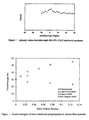
- Figure 10 shows the x-ray diffraction profiles performed on the specimens extruded from the die having a surface to volume ratio of 80 and a residence time of approximately 25 msec.
- the intensity of the x-ray diffraction at different angles indicates the distribution of fiber orientation in the composites.
- the specimens were tested so the 0 degree azimuthal angle corresponded to the preferred direction, and 90 degrees conforms to the transverse direction of the composite materials. If the fibers are aligned, the intensity of the diffraction pattern at high angles should be very low, whereas the intensity in the preferred direction (0 degrees) should be relatively high.
- the leveled intensity at ⁇ 90 degrees is the background intensity. This can be seen in Figure 10, where the fibers are oriented ⁇ 23.7, ⁇ 28.15 and ⁇ 30.0 degrees along the preferred direction for the 2.4%, 7% and 11% specimens, respectively.
- Vapor-grown carbon fiber/polypropylene mixtures containing 9%, 16.7%, and 23% vapor-grown carbon fiber by volume were prepared and processed through a Leistritz twin-screw extruder as described in the previous examples.
- the second fiber, designated, PR-21-PS (PPI) was manufactured to maximize mechanical properties. It was pyrolytically stripped and had a bulk density of approximately 48.1-64.1 kilos/m 3 (3-4 lbs/ft 3 ).
- the amalgamated blocks were first machined square. This was necessary due to the shrinkage and distortion of the blocks during the cooling process. This also eliminates any possible insulating polymer layer, which may have formed during the molding process. All three directions of the cubes were tested: with Direction 1 being the aligned or preferred direction, Direction 2 being the transverse direction, and Direction 3 being the perpendicular direction. The analysis was performed by painting the sides of the cube in the test direction using a silver conductive paint. This eliminated contact resistance of the probes and allowed for a basic two-point measurement to be performed using a digital multimeter. Resistivity (Ohm-cm) Direction 9% 16.7% 23% 1 12.63 2.87 0.57 2 23.32 3.21 2.34 3 26.29 24.64 17.63
- test specimens were formulated containing from 1% to 12.5% by volume vapor-grown carbon fibers.
- Pyrograf-III type PR-21-PS vapor-grown carbon fibers supplied by Applied Sciences, Inc. (ASI) were used along with a Pro-fax 6301 polypropylene homopolymer manufactured by Montell U.S.A., Inc.
- the carbon fibers had diameters of approximately 200 nanometers and lengths ranging from 20-80 microns.
- the samples were prepared by vacuum drying the vapor-grown carbon fibers at 300° C for three hours. This was sufficient to remove any moisture entrapped by the entangled fiber particles.
- the carbon fibers were then mixed at room temperature with the powdered polypropylene resin using a twin-shell dry blender until a homogenous mixture was formed. Since the polypropylene matrix material was not very hygroscopic, further drying of'the mixture was not necessary.
- test specimens were prepared, one containing the conventional PAN-derived carbon fibers described above (7 micron diameter, 2 to 3 mm in length) and the other containing randomly-aligned vapor-grown carbon fibers.
- the test specimen containing the randomly-aligned fiber was prepared by allowing the polymer/fiber mixture to deposit into a mold after extrusion through a large oval opening. Since the extrusion ratio is not large and the composite melt has a high flow rate into the mold, the result is a composite that had very little fiber alignment. Since the die opening is large, the extrusion pressure was negligible compared to the aligned vapor-grown carbon fibers composite.
- Degradation of composite properties can also be due to higher void content (due to lower extrusion pressure), and poor bonding between the fiber and the polymer during the extrusion process.
- the composites with 11% aligned vapor-grown carbon fibers had a tensile strength that was almost 2.5 times the non-aligned composites.
- test specimen containing the conventional PAN-derived carbon fiber also demonstrated a significant increase in tensile strength, which suggests that some alignment of the fibers occurred in these composites as well.
- amount of tensile strength increase 18.6% is considerably less than that occurring in the corresponding aligned fiber specimen made in accordance with the present invention, 37%. This is especially surprising since the conventional PAN-derived fibers are much bigger and hence subject to a much greater aligning torque during extrusion than the vapor-grown carbon fibers of the other test specimens.
Landscapes
- Chemical & Material Sciences (AREA)
- Engineering & Computer Science (AREA)
- Chemical Kinetics & Catalysis (AREA)
- Electrochemistry (AREA)
- General Chemical & Material Sciences (AREA)
- Mechanical Engineering (AREA)
- Composite Materials (AREA)
- Manufacturing & Machinery (AREA)
- Physics & Mathematics (AREA)
- Textile Engineering (AREA)
- Spectroscopy & Molecular Physics (AREA)
- Dispersion Chemistry (AREA)
- Materials Engineering (AREA)
- Compositions Of Macromolecular Compounds (AREA)
- Reinforced Plastic Materials (AREA)
- Macromonomer-Based Addition Polymer (AREA)
- Inorganic Fibers (AREA)
- Extrusion Moulding Of Plastics Or The Like (AREA)
Claims (13)
- Verfahren, umfassend das Extrudieren einer Mischung aus kurzer Verstärkungsfaser und Polymer durch eine Düsenplatte, die ein Oberflächen-zu-Volumen-Verhältnis von mindestens ungefähr 25,4 cm-1 (10 in-1) besitzt, wobei die kurze Verstärkungsfaser einen Durchmesser von ungefähr 1 Mikrometer oder geringer, eine Länge von 500 Mikrometern oder geringer und ein Aspektverhältnis von ungefähr 10 bis 750 besitzt, wodurch ein faserverstärkter Polymer-Matrix-Verbund mit anisotropen Eigenschaften hergestellt wird, die aufgrund der Orientierung der kurzen Verstärkungsfasern darin entstehen.
- Verfahren nach Anspruch 1, wobei die Mischung durch mehrere Düsenplatten-Durchgangswege extrudiert wird, um dadurch mehrere Stränge eines Extrudats zu erzeugen, wobei jeder Düsenplatten-Durchgangsweg ein Oberflächen-zu-Volumen-Verhältnis von mindestens 25,4 cm-1 (10 in-1) besitzt.
- Verfahren nach Anspruch 2, das weiterhin ein Aneinanderbonden der Stränge in einer im Wesentlichen parallelen Beziehung aufweist, um dadurch einen geformten Gegenstand mit anisotropen Eigenschaften zu bilden.
- Verfahren nach Anspruch 1, wobei die kurze Verstärkungsfaser ungefähr 200 Mikrometer oder geringer in der Länge ist.
- Verfahren nach Anspruch 4, wobei die kurze Verstärkungsfaser einen Durchmesser von ungefähr 0,5 Mikrometern oder geringer besitzt.
- Verfahren nach Anspruch 5, wobei die kurze Verstärkungsfaser ein Aspektverhältnis von ungefähr 40 zu 200 besitzt.
- Verfahren nach Anspruch 1, wobei die Düsenplatte ein Längen-zu-Breiten-Verhältnis von mindestens ungefähr 6 besitzt.
- Verfahren nach Anspruch 1, wobei die kurze Verstärkungsfaser eine mittels Dampf angewachsene Kohlefaser ist.
- Verfahren nach Anspruch 1, wobei die Mischung ungefähr 1 bis 50 Gew.-% an kurzer Verstärkungsfaser enthält.
- Verfahren, zum Herstellen eines geformten Polymergegenstands, der eine anisotrope, elektrische Leitfähigkeit besitzt, wobei das Verfahren ein Extrudieren einer Mischung des Polymers und der mittels Dampf angewachsenen Kohlefaser durch eine Düsenplatte, die ein Oberflächen-zu-Volumen-Verhältnis von mindestens ungefähr 25,4 cm-1 (10 in-1) besitzt, wobei die kurze Verstärkungsfaser einen Durchmesser von ungefähr 1 Mikrometer oder geringer, eine Länge von 500 Mikrometern oder geringer und ein Aspektverhältnis von ungefähr 10 bis 750 besitzt, um dadurch mehrere Stränge eines Extrudats herzustellen, und Aneinanderbonden der Stränge in einer im Wesentlichen parallelen Beziehung, um den geformten Gegenstand zu bilden, aufweist.
- Verfahren nach Anspruch 10, wobei die mehreren Stränge aus Extrudat durch Extrudieren der Mischung durch mehrere Düsenplatten-Durchgangswege hergestellt sind, jeder mit einem Oberflächen-zu-Volumen-Verhältnis von mindestens ungefähr 10.
- Verfahren nach Anspruch 10, wobei die parallele Richtung der Stränge eine Längsrichtung des geformten Gegenstands definiert, wobei das Verfahren weiterhin ein Unterteilen des geformten Gegenstands entlang einer Oberfläche, angeordnet quer zu der Längsrichtung, aufweist.
- Geformter Polymergegenstand, der eine anisotrope, elektrische Leitfähigkeit besitzt, wobei der Gegenstand eine Mischung des Polymers und der mittels Dampf angewachsenen Kohlefasem, angeordnet in einer im Wesentlichen parallelen Beziehung, aufweist.
Applications Claiming Priority (3)
| Application Number | Priority Date | Filing Date | Title |
|---|---|---|---|
| US22393700P | 2000-08-09 | 2000-08-09 | |
| US223937P | 2000-08-09 | ||
| PCT/US2001/041650 WO2002011971A2 (en) | 2000-08-09 | 2001-08-09 | Improved polymer matrix composite |
Publications (2)
| Publication Number | Publication Date |
|---|---|
| EP1307331A2 EP1307331A2 (de) | 2003-05-07 |
| EP1307331B1 true EP1307331B1 (de) | 2005-05-04 |
Family
ID=22838605
Family Applications (1)
| Application Number | Title | Priority Date | Filing Date |
|---|---|---|---|
| EP01975709A Expired - Lifetime EP1307331B1 (de) | 2000-08-09 | 2001-08-09 | Verbundmaterial mit polymermatrix |
Country Status (7)
| Country | Link |
|---|---|
| US (1) | US20050074993A1 (de) |
| EP (1) | EP1307331B1 (de) |
| AT (1) | ATE294688T1 (de) |
| AU (1) | AU2001295003A1 (de) |
| CA (1) | CA2419134A1 (de) |
| DE (1) | DE60110605T2 (de) |
| WO (1) | WO2002011971A2 (de) |
Families Citing this family (15)
| Publication number | Priority date | Publication date | Assignee | Title |
|---|---|---|---|---|
| JP3962862B2 (ja) * | 2002-02-27 | 2007-08-22 | 日立造船株式会社 | カーボンナノチューブを用いた導電性材料およびその製造方法 |
| JP2005019393A (ja) * | 2003-06-05 | 2005-01-20 | Sharp Corp | 異方性導電物、表示装置、表示装置の製造方法および導電部材 |
| US20060280938A1 (en) * | 2005-06-10 | 2006-12-14 | Atkinson Paul M | Thermoplastic long fiber composites, methods of manufacture thereof and articles derived thererom |
| DE102011005666A1 (de) * | 2011-03-16 | 2012-09-20 | Sgl Carbon Se | Verfahren zur Herstellung von aktiviertem Kohlenstoff aus faserverstärkten Verbundwerkstoff enthaltendem Ausgangsmaterial |
| US20130065128A1 (en) * | 2011-09-12 | 2013-03-14 | The Board Of Trustees Of The Leland Stanford Junior University | Encapsulated sulfur cathodes for rechargeable lithium batteries |
| DE102011121054B4 (de) * | 2011-12-14 | 2024-08-08 | Airbus Operations Gmbh | Riblet-Struktur auf einer Strömungsfläche, Verfahren zum Herstellen einer Riblet-Struktur auf einer Strömungsfläche und Verwendung von Verstärkungselementen in Riblets für eine Strömungsfläche |
| US9821339B2 (en) | 2014-12-19 | 2017-11-21 | Palo Alto Research Center Incorporated | System and method for digital fabrication of graded, hierarchical material structures |
| US9486960B2 (en) | 2014-12-19 | 2016-11-08 | Palo Alto Research Center Incorporated | System for digital fabrication of graded, hierarchical material structures |
| US10160004B2 (en) | 2015-07-07 | 2018-12-25 | Palo Alto Research Center Incorporated | Creating aligned and oriented fiber reinforced polymer composites |
| US10920041B2 (en) * | 2015-08-11 | 2021-02-16 | South Dakota Board Of Regents | Discontinuous-fiber composites and methods of making the same |
| ITUB20160438A1 (it) | 2016-02-05 | 2017-08-05 | Renolit Gor Spa | Lastra in materiale composito e relativo procedimento di fabbricazione |
| US10947419B2 (en) | 2018-07-23 | 2021-03-16 | Palo Alto Research Center Incorporated | Method for joining dissimilar materials |
| US11351744B2 (en) | 2019-03-29 | 2022-06-07 | The Boeing Company | Molten extrusion loading for compression molds using chopped prepreg fiber |
| CN111016258B (zh) * | 2019-11-18 | 2020-09-04 | 苏州鸿凌达电子科技有限公司 | 应用于石墨烯纤维取向排列挤出成型设备 |
| US20230107417A1 (en) * | 2021-10-04 | 2023-04-06 | The Boeing Company | Reinforcing a junction in a fiber-composite conduit |
Family Cites Families (15)
| Publication number | Priority date | Publication date | Assignee | Title |
|---|---|---|---|---|
| JPS5265892A (en) * | 1975-11-26 | 1977-05-31 | Shinetsu Polymer Co | Nonnisotropic conductiveesheet type composite materials and method of manufacture thereof |
| US4449774A (en) * | 1981-02-05 | 1984-05-22 | Shin-Etsu Polymer Co., Ltd. | Electroconductive rubbery member and elastic connector therewith |
| US4820170A (en) * | 1984-12-20 | 1989-04-11 | Amp Incorporated | Layered elastomeric connector and process for its manufacture |
| JPH07118323B2 (ja) * | 1986-07-14 | 1995-12-18 | 呉羽化学工業株式会社 | 電極基板の製造方法 |
| JPH01184241A (ja) * | 1988-01-18 | 1989-07-21 | Honda Motor Co Ltd | 複合材料用短繊維成形体、短繊維強化複合材料用素材および短繊維強化複合材料における短繊維の配向制御方法 |
| WO1991006131A1 (fr) * | 1989-10-17 | 1991-05-02 | Kureha Kagaku Kogyo Kabushiki Kaisha | Materiau en carbone poreux pourvu de nervures en forme de feuilles plates et procede de production |
| US5093050A (en) * | 1989-11-17 | 1992-03-03 | Laboratorium Fur Experimentelle Chirurgie | Method for producing oriented, discontinuous fiber reinforced composite materials |
| US5024818A (en) * | 1990-10-09 | 1991-06-18 | General Motors Corporation | Apparatus for forming carbon fibers |
| CA2146435A1 (en) * | 1992-10-29 | 1994-05-11 | John P. Dismukes | Composites and methods of manufacturing the same |
| US5401154A (en) * | 1993-05-26 | 1995-03-28 | Continental Structural Plastics, Inc. | Apparatus for compounding a fiber reinforced thermoplastic material and forming parts therefrom |
| US5433906A (en) * | 1993-07-09 | 1995-07-18 | General Motors Corporation | Composite of small carbon fibers and thermoplastics and method for making same |
| WO1996034045A1 (en) * | 1995-04-27 | 1996-10-31 | Aviplast Bv | Plastic-based composite product and method and apparatus for manufacturing same |
| JP3502490B2 (ja) * | 1995-11-01 | 2004-03-02 | 昭和電工株式会社 | 炭素繊維材料及びその製造法 |
| JP3183845B2 (ja) * | 1997-03-21 | 2001-07-09 | 財団法人ファインセラミックスセンター | カーボンナノチューブ及びカーボンナノチューブ膜の製造方法 |
| US6156256A (en) * | 1998-05-13 | 2000-12-05 | Applied Sciences, Inc. | Plasma catalysis of carbon nanofibers |
-
2001
- 2001-08-09 CA CA002419134A patent/CA2419134A1/en not_active Abandoned
- 2001-08-09 US US10/344,088 patent/US20050074993A1/en not_active Abandoned
- 2001-08-09 AT AT01975709T patent/ATE294688T1/de not_active IP Right Cessation
- 2001-08-09 DE DE60110605T patent/DE60110605T2/de not_active Expired - Fee Related
- 2001-08-09 WO PCT/US2001/041650 patent/WO2002011971A2/en not_active Ceased
- 2001-08-09 EP EP01975709A patent/EP1307331B1/de not_active Expired - Lifetime
- 2001-08-09 AU AU2001295003A patent/AU2001295003A1/en not_active Abandoned
Also Published As
| Publication number | Publication date |
|---|---|
| AU2001295003A1 (en) | 2002-02-18 |
| ATE294688T1 (de) | 2005-05-15 |
| WO2002011971B1 (en) | 2002-09-12 |
| WO2002011971A2 (en) | 2002-02-14 |
| WO2002011971A3 (en) | 2002-06-13 |
| US20050074993A1 (en) | 2005-04-07 |
| DE60110605D1 (de) | 2005-06-09 |
| CA2419134A1 (en) | 2002-02-14 |
| EP1307331A2 (de) | 2003-05-07 |
| DE60110605T2 (de) | 2006-01-19 |
Similar Documents
| Publication | Publication Date | Title |
|---|---|---|
| EP1307331B1 (de) | Verbundmaterial mit polymermatrix | |
| Kuriger et al. | Processing and characterization of aligned vapor grown carbon fiber reinforced polypropylene | |
| Spoerk et al. | Anisotropic properties of oriented short carbon fibre filled polypropylene parts fabricated by extrusion-based additive manufacturing | |
| US5433906A (en) | Composite of small carbon fibers and thermoplastics and method for making same | |
| US7198745B2 (en) | Method for forming a fibers/composite material having an anisotropic structure | |
| US7767302B2 (en) | Pitch-based carbon fiber, web and resin molded product containing them | |
| DE60033692T2 (de) | Orientierte, in eine Polymer-Matrix eingebettete Nanofasern | |
| US9362018B2 (en) | Impregnated continuous graphitic fiber tows and composites containing same | |
| TW201915053A (zh) | 碳纖維及奈米管對聚合物基質之原位鍵結 | |
| Esawi et al. | Effect of processing technique on the dispersion of carbon nanotubes within polypropylene carbon nanotube‐composites and its effect on their mechanical properties | |
| DE69605994T2 (de) | Gebündelte Masse kurzer Kohlenstoffaser, Verfahren zu deren Herstellung, und faserverstärkte Harzzusammensetzung | |
| JPS6246925B2 (de) | ||
| Kuriger et al. | Extrusion conditions and properties of vapor grown carbon fiber reinforced polypropylene | |
| Kuriger et al. | Improved thermoplastic composite by alignment of vapor grown carbon fiber | |
| Khalid et al. | Rheological test of flowability and diffusion behavior of carbon fibre reinforced polyamide | |
| EP1818358A1 (de) | In einer Polymermatrix eingebettete, orientierte Nanofasern | |
| JPH09157403A (ja) | 炭素短繊維集合体及びその製造方法並びに繊維強化樹脂組成物 | |
| Ji et al. | Comparison of tensile fracture morphologies among various polyacrylonitrile-based carbon fibers | |
| Biswas et al. | Comparative study of zeolite-filled LLDPE and HDPE composite films | |
| Eyercioğlu et al. | Single bead property of short fiber carbon reinforced ABS composites produced with large scale additive manufacturing (LSAM) | |
| Fujita et al. | Interfacial shear strength measurement of C/C using a microcomposite | |
| CN121293720A (zh) | 一种高强度高导热cf-peek粒子的制备方法 | |
| Barrera et al. | Oriented nanofibers embedded in a polymer matrix | |
| Sahli | Elaboration and study of the electro-thermo-mechanical properties of an aligned carbon nanotubes-polypropylene composite by twin-screw mixer | |
| Gümrük et al. | Additive Manufacturing of Continuous Fiber-Reinforced Composites with High Mechanical Properties From PLA Thermoplastic Resin by Fused Deposition Method |
Legal Events
| Date | Code | Title | Description |
|---|---|---|---|
| PUAI | Public reference made under article 153(3) epc to a published international application that has entered the european phase |
Free format text: ORIGINAL CODE: 0009012 |
|
| 17P | Request for examination filed |
Effective date: 20030212 |
|
| AK | Designated contracting states |
Designated state(s): AT BE CH CY DE DK ES FI FR GB GR IE IT LI LU MC NL PT SE TR |
|
| AX | Request for extension of the european patent |
Extension state: AL LT LV MK RO SI |
|
| 17Q | First examination report despatched |
Effective date: 20040408 |
|
| GRAP | Despatch of communication of intention to grant a patent |
Free format text: ORIGINAL CODE: EPIDOSNIGR1 |
|
| GRAS | Grant fee paid |
Free format text: ORIGINAL CODE: EPIDOSNIGR3 |
|
| GRAA | (expected) grant |
Free format text: ORIGINAL CODE: 0009210 |
|
| AK | Designated contracting states |
Kind code of ref document: B1 Designated state(s): AT BE CH CY DE DK ES FI FR GB GR IE IT LI LU MC NL PT SE TR |
|
| PG25 | Lapsed in a contracting state [announced via postgrant information from national office to epo] |
Ref country code: IT Free format text: LAPSE BECAUSE OF FAILURE TO SUBMIT A TRANSLATION OF THE DESCRIPTION OR TO PAY THE FEE WITHIN THE PRESCRIBED TIME-LIMIT;WARNING: LAPSES OF ITALIAN PATENTS WITH EFFECTIVE DATE BEFORE 2007 MAY HAVE OCCURRED AT ANY TIME BEFORE 2007. THE CORRECT EFFECTIVE DATE MAY BE DIFFERENT FROM THE ONE RECORDED. Effective date: 20050504 Ref country code: TR Free format text: LAPSE BECAUSE OF FAILURE TO SUBMIT A TRANSLATION OF THE DESCRIPTION OR TO PAY THE FEE WITHIN THE PRESCRIBED TIME-LIMIT Effective date: 20050504 Ref country code: AT Free format text: LAPSE BECAUSE OF FAILURE TO SUBMIT A TRANSLATION OF THE DESCRIPTION OR TO PAY THE FEE WITHIN THE PRESCRIBED TIME-LIMIT Effective date: 20050504 Ref country code: CH Free format text: LAPSE BECAUSE OF FAILURE TO SUBMIT A TRANSLATION OF THE DESCRIPTION OR TO PAY THE FEE WITHIN THE PRESCRIBED TIME-LIMIT Effective date: 20050504 Ref country code: BE Free format text: LAPSE BECAUSE OF FAILURE TO SUBMIT A TRANSLATION OF THE DESCRIPTION OR TO PAY THE FEE WITHIN THE PRESCRIBED TIME-LIMIT Effective date: 20050504 Ref country code: LI Free format text: LAPSE BECAUSE OF FAILURE TO SUBMIT A TRANSLATION OF THE DESCRIPTION OR TO PAY THE FEE WITHIN THE PRESCRIBED TIME-LIMIT Effective date: 20050504 Ref country code: FI Free format text: LAPSE BECAUSE OF FAILURE TO SUBMIT A TRANSLATION OF THE DESCRIPTION OR TO PAY THE FEE WITHIN THE PRESCRIBED TIME-LIMIT Effective date: 20050504 Ref country code: NL Free format text: LAPSE BECAUSE OF FAILURE TO SUBMIT A TRANSLATION OF THE DESCRIPTION OR TO PAY THE FEE WITHIN THE PRESCRIBED TIME-LIMIT Effective date: 20050504 |
|
| REG | Reference to a national code |
Ref country code: GB Ref legal event code: FG4D |
|
| REG | Reference to a national code |
Ref country code: CH Ref legal event code: EP |
|
| REG | Reference to a national code |
Ref country code: IE Ref legal event code: FG4D |
|
| REF | Corresponds to: |
Ref document number: 60110605 Country of ref document: DE Date of ref document: 20050609 Kind code of ref document: P |
|
| PGFP | Annual fee paid to national office [announced via postgrant information from national office to epo] |
Ref country code: GB Payment date: 20050629 Year of fee payment: 5 |
|
| PG25 | Lapsed in a contracting state [announced via postgrant information from national office to epo] |
Ref country code: DK Free format text: LAPSE BECAUSE OF FAILURE TO SUBMIT A TRANSLATION OF THE DESCRIPTION OR TO PAY THE FEE WITHIN THE PRESCRIBED TIME-LIMIT Effective date: 20050804 Ref country code: GR Free format text: LAPSE BECAUSE OF FAILURE TO SUBMIT A TRANSLATION OF THE DESCRIPTION OR TO PAY THE FEE WITHIN THE PRESCRIBED TIME-LIMIT Effective date: 20050804 Ref country code: SE Free format text: LAPSE BECAUSE OF FAILURE TO SUBMIT A TRANSLATION OF THE DESCRIPTION OR TO PAY THE FEE WITHIN THE PRESCRIBED TIME-LIMIT Effective date: 20050804 |
|
| PG25 | Lapsed in a contracting state [announced via postgrant information from national office to epo] |
Ref country code: CY Free format text: LAPSE BECAUSE OF FAILURE TO SUBMIT A TRANSLATION OF THE DESCRIPTION OR TO PAY THE FEE WITHIN THE PRESCRIBED TIME-LIMIT Effective date: 20050809 Ref country code: LU Free format text: LAPSE BECAUSE OF NON-PAYMENT OF DUE FEES Effective date: 20050809 |
|
| PG25 | Lapsed in a contracting state [announced via postgrant information from national office to epo] |
Ref country code: ES Free format text: LAPSE BECAUSE OF FAILURE TO SUBMIT A TRANSLATION OF THE DESCRIPTION OR TO PAY THE FEE WITHIN THE PRESCRIBED TIME-LIMIT Effective date: 20050815 |
|
| PGFP | Annual fee paid to national office [announced via postgrant information from national office to epo] |
Ref country code: IE Payment date: 20050824 Year of fee payment: 5 |
|
| PG25 | Lapsed in a contracting state [announced via postgrant information from national office to epo] |
Ref country code: MC Free format text: LAPSE BECAUSE OF NON-PAYMENT OF DUE FEES Effective date: 20050831 |
|
| PGFP | Annual fee paid to national office [announced via postgrant information from national office to epo] |
Ref country code: DE Payment date: 20050929 Year of fee payment: 5 |
|
| PG25 | Lapsed in a contracting state [announced via postgrant information from national office to epo] |
Ref country code: PT Free format text: LAPSE BECAUSE OF FAILURE TO SUBMIT A TRANSLATION OF THE DESCRIPTION OR TO PAY THE FEE WITHIN THE PRESCRIBED TIME-LIMIT Effective date: 20051017 |
|
| NLV1 | Nl: lapsed or annulled due to failure to fulfill the requirements of art. 29p and 29m of the patents act | ||
| REG | Reference to a national code |
Ref country code: CH Ref legal event code: PL |
|
| PLBE | No opposition filed within time limit |
Free format text: ORIGINAL CODE: 0009261 |
|
| STAA | Information on the status of an ep patent application or granted ep patent |
Free format text: STATUS: NO OPPOSITION FILED WITHIN TIME LIMIT |
|
| 26N | No opposition filed |
Effective date: 20060207 |
|
| EN | Fr: translation not filed | ||
| PG25 | Lapsed in a contracting state [announced via postgrant information from national office to epo] |
Ref country code: IE Free format text: LAPSE BECAUSE OF NON-PAYMENT OF DUE FEES Effective date: 20060809 |
|
| PG25 | Lapsed in a contracting state [announced via postgrant information from national office to epo] |
Ref country code: DE Free format text: LAPSE BECAUSE OF NON-PAYMENT OF DUE FEES Effective date: 20070301 |
|
| GBPC | Gb: european patent ceased through non-payment of renewal fee |
Effective date: 20060809 |
|
| REG | Reference to a national code |
Ref country code: IE Ref legal event code: MM4A |
|
| PG25 | Lapsed in a contracting state [announced via postgrant information from national office to epo] |
Ref country code: GB Free format text: LAPSE BECAUSE OF NON-PAYMENT OF DUE FEES Effective date: 20060809 |
|
| PG25 | Lapsed in a contracting state [announced via postgrant information from national office to epo] |
Ref country code: FR Free format text: LAPSE BECAUSE OF NON-PAYMENT OF DUE FEES Effective date: 20050831 |
|
| PG25 | Lapsed in a contracting state [announced via postgrant information from national office to epo] |
Ref country code: FR Free format text: LAPSE BECAUSE OF NON-PAYMENT OF DUE FEES Effective date: 20050504 |