EP1307971B1 - Interferenzimmunitätsregelung eines empfängers durch linearitätsregelung - Google Patents
Interferenzimmunitätsregelung eines empfängers durch linearitätsregelung Download PDFInfo
- Publication number
- EP1307971B1 EP1307971B1 EP01956083A EP01956083A EP1307971B1 EP 1307971 B1 EP1307971 B1 EP 1307971B1 EP 01956083 A EP01956083 A EP 01956083A EP 01956083 A EP01956083 A EP 01956083A EP 1307971 B1 EP1307971 B1 EP 1307971B1
- Authority
- EP
- European Patent Office
- Prior art keywords
- noise amplifier
- low noise
- interference
- level
- mobile station
- Prior art date
- Legal status (The legal status is an assumption and is not a legal conclusion. Google has not performed a legal analysis and makes no representation as to the accuracy of the status listed.)
- Expired - Lifetime
Links
- 230000036039 immunity Effects 0.000 title description 10
- 238000000034 method Methods 0.000 claims description 54
- 230000000737 periodic effect Effects 0.000 claims description 7
- 238000012544 monitoring process Methods 0.000 claims description 4
- 238000001228 spectrum Methods 0.000 claims 2
- 238000005259 measurement Methods 0.000 abstract description 2
- 230000001413 cellular effect Effects 0.000 description 10
- 238000004891 communication Methods 0.000 description 4
- 238000010586 diagram Methods 0.000 description 4
- 230000005540 biological transmission Effects 0.000 description 2
- 238000013461 design Methods 0.000 description 2
- 230000000694 effects Effects 0.000 description 2
- 230000002452 interceptive effect Effects 0.000 description 2
- 230000003321 amplification Effects 0.000 description 1
- 239000000969 carrier Substances 0.000 description 1
- 238000006243 chemical reaction Methods 0.000 description 1
- 230000003247 decreasing effect Effects 0.000 description 1
- 230000001419 dependent effect Effects 0.000 description 1
- 230000003116 impacting effect Effects 0.000 description 1
- 238000003199 nucleic acid amplification method Methods 0.000 description 1
Images


Classifications
-
- H—ELECTRICITY
- H04—ELECTRIC COMMUNICATION TECHNIQUE
- H04B—TRANSMISSION
- H04B1/00—Details of transmission systems, not covered by a single one of groups H04B3/00 - H04B13/00; Details of transmission systems not characterised by the medium used for transmission
- H04B1/06—Receivers
- H04B1/10—Means associated with receiver for limiting or suppressing noise or interference
- H04B1/109—Means associated with receiver for limiting or suppressing noise or interference by improving strong signal performance of the receiver when strong unwanted signals are present at the receiver input
-
- H—ELECTRICITY
- H04—ELECTRIC COMMUNICATION TECHNIQUE
- H04B—TRANSMISSION
- H04B1/00—Details of transmission systems, not covered by a single one of groups H04B3/00 - H04B13/00; Details of transmission systems not characterised by the medium used for transmission
- H04B1/06—Receivers
- H04B1/10—Means associated with receiver for limiting or suppressing noise or interference
- H04B1/1027—Means associated with receiver for limiting or suppressing noise or interference assessing signal quality or detecting noise/interference for the received signal
Definitions
- the present invention relates generally to radio communications. Particularly, the present invention relates to improving a communication receiver's immunity to interference.
- cellular telephone systems There are multiple types of cellular telephone systems in operation. These systems include the advanced mobile phone system (AMPS) and two digital cellular systems: time division multiple access (TDMA) and code division multiple access (CDMA).
- AMPS advanced mobile phone system
- TDMA time division multiple access
- CDMA code division multiple access
- Cellular systems operate by typically locating multiple antennas in the center of a cell covering a geographic region.
- the AMPS cells are separate and distinct from the CDMA cells so that the cells of each system overlap. This makes it likely that the antenna for one system's cell may be located in a cell of another system.
- AMPS AMPS
- CDMA Code Division Multiple Access
- TDMA Time Division Multiple Access
- a telephone on system 'A' might be far away from the nearest system 'A' cell while close to a system 'B' cell. This situation means that the desired receive signal might be weak in the presence of strong multi-tone interference.
- the intermixing of system antennas can cause problems for a mobile station that is registered in one system, such as the CDMA system, and travels near another system's antenna, such as an AMPS antenna.
- the signals from the AMPS antenna can interfere with the CDMA signals being received by the mobile station due to the proximity of the mobile station with the AMPS cell or the higher power of the AMPS forward link signal. This is referred to in the art as 'jamming'.
- One way to improve the immunity of a receiver to interference or jamming is to increase the current to the receiver. This is not a practical solution, however, for a mobile station that relies on battery power. Increasing the current would drain the battery more rapidly, thereby decreasing the talk and standby time of the mobile station. Additionally, a detector is typically used to detect the presence of the jamming signal. However, by the time the jamming signal has been detected and the linearity of the receiver increased, the jamming signal may no longer exist.
- US patent number US5179724 discloses the operation of a radio communication system such as a cellular telephone system having battery powered mobile stations which receive radio frequency signals and an amplifier in the receiver of the mobile station, in a plurality of different modes in order to reduce power consumption.
- the modes of the amplifier depend upon the strength of the incoming signal and whether the transmitter is transmitting.
- the receiver is also periodically disconnected from the battery in order to further reduce power consumption.
- International application WO0018023 discloses a method and system for intelligently controlling the linearity of an RF receiver by selectively increasing the effective third-order intercept point (IP3) value of a low noise amplifier (LNA)/mixer channel only when needed.
- a control signal is generated based on mode of operation (receive mode); received signal strength information (RSSI); transmit channel output power, as indicated by a Tx automatic gain control (AGC) signal; and the true received signal strength, as indicated by the pilot signal-to-noise ratio in a CDMA system.
- the control signal is then used to selectively increase the bias current - and thus linearity - of the LNA/mixer channel, or to select one of several LNAs having differing IP3 values to effectively increase the linearity of the LNA/mixer channel.
- the present invention as set out in the appended claims provides control of the linearity of a low noise amplifier in a receiver of a mobile station. This provides the desired level of immunity to Interference while reducing the average current consumption of the receiver. In a battery powered device, reducing the current consumption has the effect of increasing talk and stand-by times.
- the present invention encompasses a process for controlling the linearity of a low noise amplifier.
- the low noise amplifier Is first enabled. It is then determined if a predicted level of interference will produce an acceptable bit error rate or other signal error measurement.
- the low noise amplifier is adjusted to a high level of linearity. If the predicted level of interference is acceptable, the low noise amplifier is set to a low level of linearity.
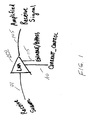
- FIG. 1 shows a block diagram of a low noise amplifier of the present invention.
- FIG. 2 shows an embodiment of the enable/bypass function in accordance with the low noise amplifier of the present invention.
- FIG. 3 shows a flowchart of the present invention for changing the linearity of a low noise amplifier.
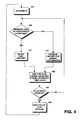
- FIG. 4 shows a flowchart of an alternate embodiment process of the present invention.
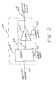
- FIG. 5 shows a block diagram of a receiver incorporating the low noise amplifier of the present invention.
- the present invention provides different levels of immunity, in response to a control signal, to predicted levels of interference.
- Current consumption is improved by reducing the low noise amplifier's (LNA) linearity when reduced immunity provides a desired level of performance (e.g., bit error rate).
- LNA low noise amplifier's
- Increasing the LNA's linearity when greater immunity is required increases the receiver's immunity to interference. This linearity control is based on a predicted or expected level of interference.
- FIG. 1 illustrates a block diagram of the preferred embodiment of the LNA (100) of the present invention.
- the LNA is comprised of an input received signal (101).
- this received signal (101) is at a radio frequency for the system in which the LNA (100) is operating.
- the amplified received signal (105) is output from the LNA.
- the level of amplification of the received signal (101) is dependent upon the current control signal (110) and the enable/bypass signal (115) of the present invention.
- FIG. 2 illustrates an example of an enables/bypass function of the present invention.
- the enable/bypass function incorporated into the LNA (100) is comprised of a demultiplexer (205).
- the received signal (101) is the input signal to the demultiplexer (205).
- the enable/bypass signal (115) selects between one of the two outputs (210 and 215) of the demultiplexer (205).
- the first output (210) bypasses the LNA function (225) of the present invention.
- the second output (215) is an input to the LNA function (225) of the present invention.
- the current control signal (110) is input to the LNA function (225).
- the amplified received signal (105) is output from the LNA function (225).
- the enable/bypass function shown in FIG. 2 is for illustration purposes only and is just one example of such an enable/bypass function. Many different switching scenarios may perform this function. The present invention is not limited to any one of these various scenarios.
- FIG. 3 illustrates a flowchart of a process of the present invention for controlling the LNA's linearity by the current control signal.
- the LNA is set to either a low or high linearity setting by a step function current control signal.
- the process begins with the LNA being enabled (step 301). This enablement may be performed as illustrated in FIG. 2 or using any other enabling means.
- the level of interference is predicted to determine if it will be acceptable for a desired performance level of the mobile station (step 305).
- the level of interference may be predicted based on many factors: the location of the mobile station and the frequency on which the mobile station is operating (i.e., which service provider it is using), the power control commands sent to the mobile station, the current operating mode of the mobile station, the strength of a received signal, the strength of a transmitted signal, the current level of interference, acceptable level of interference, and whether the LNA is enabled or bypassed.
- Whether the predicted level of interference is acceptable may be based on one or a combination of the above factors. Some of these factors may not be weighted equally. For example, the acceptable level of interference may be considered more important in predicting the interference level than the other factors so this will be weighted more than the other factors.
- a second cellular system When a first cellular system is installed in a certain geographical location, it may be known that a second cellular system is operating on a frequency that interferes with some, or all, of the channels of the first cellular system. Additionally, other interfering transmissions in the area, such as the emergency radio band, may be known to cause interference to some, or all, of the channels of the first cellular system.
- Another factor in predicting the level of interference is the power control commands received by the mobile station.
- the mobile station receives a number of "increase power" commands from the base station this may be an indication that an area of high interference is being entered.
- the operating mode of the mobile station includes on which frequency the mobile station is operating. As discussed above, it may be known that a certain frequency band experiences a certain level of interference. Therefore, if the mobile station is in the CDMA mode and it is known that an AMPS signal interferes with CDMA signals in the area, this will be used by the process of the present invention to predict the level of interference.
- the strength of a received or transmitted signal is another indication in predicting the level of interference.
- the received signal strength indicates the level of interference by comparing periodic samples of the received power to a predetermined threshold or, in the case of non-binary linearity, thresholds.
- the transmit signal strength indicates the level of interference by comparing periodic samples of the transmit power to the predetermined threshold or thresholds.
- Interference can be internally or externally generated.
- the mobile station's transmitter can generate internal interference.
- the interference can be acceptable.
- the internally generated interference can be predicted based on a combination of the current operating mode and/or the strength of the transmitted signal.
- Externally generated interference can be detected by various methods such as the method illustrated and discussed subsequently in relation to the embodiment of FIG. 5 .
- Yet another indication in predicting the level of interference is whether the LNA is enabled or bypassed/disabled. When the LNA is disabled, increasing the LNA linearity is not necessary.
- a "low” linearity mode of the LNA is selected (step 310). In one embodiment, this may be accomplished by setting the current control signal to a predetermined fixed "low” level.
- the current control signal required to operate the LNA in the "low" linearity mode may be determined by experimentation.
- the level of linearity required by the LNA for adequate performance of the receiver operating in the predicted level of interference may also be determined by experimentation.
- the predetermined threshold of interference that is acceptable for proper operation of the mobile station was determined during the design of the mobile station. This threshold cannot be specified as being in any one range since it varies with the design of the mobile station.
- the acceptable level of operation is determined by the symbol error rate (SER) of the amplified received signal. Alternate embodiments use other forms of error determination.
- a "high" linearity mode of the LNA is selected (315).
- the current control signal required to operate the LNA in the "high” linearity mode may be determined by experimentation.
- step 320 various predetermined criteria are then checked to determine if anything has changed (step 320) that would require changing the LNA's linearity. These criteria include whether the mobile station's mode has changed, whether the LNA has been enabled or disabled, or whether a periodic timer has expired. The process waits for one of these criteria to change before proceeding (step 320).
- the LNA has been disabled, an attempt to change the linearity of the LNA will have no effect. Additionally, after a certain amount of time it can be assumed that the mobile station has entered another level of interference and the linearity of the LNA should be changed. This can be checked by determining the time from the last adjustment to the LNA's linearity. Comparing his time to a threshold time gives an indication of when the interference level should be rechecked. This threshold time will vary for different situations. Some situations may require periodic timer checks every few microseconds. Other situations may require periodic checks every hundred milliseconds.
- step 325 if it has been determined that the LNA has not been disabled (step 325) the process returns to predicting whether or not the level of interference is acceptable (step 305). If it has been determined that the LNA is being disabled (step 325), the process then waits for the LNA to be enabled (step 330). When this occurs, the process returns to the first step in the process when the LNA was enabled (step 301).
- FIG. 4 illustrates a flowchart of an alternate embodiment process of the present invention. While the embodiment of FIG. 3 uses a step function as the current control signal, the embodiment of FIG. 4 uses a continuously variable signal as the current control signal.
- FIG. 4 is similar to the process illustrated in FIG. 3 in that the LNA is enabled (step 401) and the predicted level of interference is checked for acceptability (step 405). If the predicted interference level is acceptable, the linearity is set for low linearity mode (step 410).
- the linearity mode is continuously varied until the desired performance level is achieved (step 415).
- the desired performance level is determined by monitoring the error rate of the amplified received signal output by the LNA. When the error determination reaches a predetermined threshold, the current control signal is held at this point until the next decision is required. Alternate embodiments use other methods for determining the desired performance level and for adjusting the current control signal to achieve the desired performance level.
- the process waits for either a mode change, the LNA enablement to change, with a periodic timer check to expire (step 420). If the LNA has been disabled (step 425), the process waits for the LNA to be enabled (step 430). If the LNA has not been disabled (step 425), the process returns to predicting if the interference level is acceptable (step 405).
- FIG. 5 illustrates one embodiment of a mobile station incorporating the apparatus of the present invention for controlling receiver immunity to interference.
- This embodiment uses a switching function (505) to enable/bypass the LNA function (500) instead of the demultiplexer illustrated in FIG. 2 .
- the apparatus of FIG. 5 is for illustration purposes only. The present invention can be incorporated in other receivers.
- This embodiment is comprised of an antenna (575) that receives and transmits radio signals.
- the transmit path (565) in the radio is coupled to the antenna (575) through a duplexer (560) that separates the received signals from the transmitted signals.
- Received signals from the duplexer (560) are input to the LNA (500).
- the amplified signal from the LNA (500) is output to a bandpass filter (515).
- the LNA (500) may be bypassed by a switch (505) coupled to a bypass path (506).
- the bypass path (506) in conjunction with the switch (505), provides a path around the LNA (500) such that the LNA (500) is disabled when the switch (505) is closed.
- the switch (505) is controlled by the mobile station's controller (510).
- the controller (510) enables or disables the LNA (500) according to the processes of the present invention.
- the controller (510) may be a microprocessor, a microcontroller, or some other type of controlling circuit that runs the processes illustrated in FiGs. 3 and 4 .
- the filtered signal is down-converted to a lower intermediate frequency (IF) for use by the rest of the mobile station.
- IF intermediate frequency
- the down-conversion is done by mixing (520) to received signal with another signal having a frequency set by phase locked loop (535) driving a voltage-controlled oscillator (530). This signal is amplified (525) before being input to the mixer (520).
- the down converted signal from the mixer (520) is input to a back end AGC (540 and 545).
- This AGC is used by the mobile station for closed loop power control, as is well known in the art.
- the current control signal (550) to the LNA (500) is produced by the mobile station controller (510).
- the controller (510) produces a step function as required by the process illustrated in FIG. 3 .
- the controller (510) produces a continuous control signal (550) as required by the process illustrated in FIG. 4 .
- the controller (510) may also be monitoring the output signal from the AGC (540 and 545) as a way of detecting the current level of interference as discussed previously. This current level of interference is used in conjunction with the other factors discussed above in controlling the enabled/bypass switch (505) and generating the continuously variable current control signal (550). In this manner, the controller (510) controls the linearity of the LNA (500) in different environments comprising various levels of interference.
- the mobile station is a cellular telephone
- the processes and apparatus of the present invention can be incorporated into other types of mobile stations.
- the mobile station may be a modem built into a lap top computer, a personal digital assistant having the capability of receiving radio frequency signals, or any other type of communications device that would benefit from a receiver that changes it's linearity in response to a predicted level of interference.
- the present invention enables a mobile station to travel near antennas of different systems while increasing the mobile station's resistance to radio frequency interference from the other systems. This is accomplished without impacting the talk or standby time of the mobile station.
- Prior art systems used either a higher linearity LNA, at the expense of power, or would have failed when they encountered significant interference.
Landscapes
- Engineering & Computer Science (AREA)
- Computer Networks & Wireless Communication (AREA)
- Signal Processing (AREA)
- Noise Elimination (AREA)
- Mobile Radio Communication Systems (AREA)
- Input Circuits Of Receivers And Coupling Of Receivers And Audio Equipment (AREA)
- Amplifiers (AREA)
- Circuits Of Receivers In General (AREA)
- Optical Communication System (AREA)
- Details Of Television Scanning (AREA)
Claims (30)
- Ein Verfahren zum Steuern von Linearität von einem rauscharmen Verstärker (100), wobei das Verfahren die folgenden Schritte aufweist:Aktivieren des rauscharmen Verstärkers (301);Bestimmen, ob ein prognostizierter Pegel an Interferenz akzeptabel ist (305); undfalls der prognostizierte Pegel an Interferenz akzeptabel ist, Wählen eines niedrigen Pegels von Linearität für den rauscharmen Verstärker (310),gekennzeichnet dadurch, dass das Verfahren ferner die folgenden Schritte aufweist:Warten auf eine Änderung in vorher bestimmten Kriterien zum Bestimmen, ob sich irgendetwas geändert hat, dass das Ändern der Linearität des rauscharmen Verstärkers erforderlich machen würde (320);wenn sich eines der vorher bestimmten Kriterien geändert hat, Bestimmen ob der rauscharme Verstärker noch aktiviert ist;falls der rauscharme Verstärker noch aktiviert ist, Zurückkehren zu dem Schritt zum Bestimmen, ob der vorher bestimmte Pegel an Interferenz akzeptabel ist (305); undfalls der rauscharme Verstärker nicht aktiviert ist, Warten darauf, dass der rauscharme Verstärker wieder aktiviert (330) wird.
- Verfahren nach Anspruch 1, wobei das Verfahren ferner den Schritt aufweist zum Wählen eines hohen Pegels an Linearität für den rauscharmen Verstärker (315), falls der prognostizierte Pegel an Interferenz nicht akzeptabel ist.
- Verfahren nach Anspruch 1, wobei die vorher bestimmten Kriterien eine Änderung in einer Frequenzspektrumseingabe an den rauscharmen Verstärker, eine Änderung in der Aktivierung von dem rauscharmen Verstärker und einen Ablauf von einer vorher bestimmten Zeit beinhalten.
- Verfahren nach Anspruch 3, wobei die vorher bestimmte Zeit eine Zeit aufweist, in der für den rauscharmen Verstärker prognostiziert wird, dass sich dieser aus einem Gebiet heraus bewegt, das unakzeptable Interferenzpegel aufweist.
- Verfahren nach Anspruch 2, wobei der Schritt zum Wählen eines hohen Pegels an Linearität für den rauscharmen Verstärker Wählen eines hohen Pegels in einer Steuersignalschrittfunktion, die mit dem rauscharmen Verstärker gekoppelt ist, aufweist.
- Verfahren nach Anspruch 1, wobei der Schritt des Wählens eines niedrigen Pegels an Linearität für den rauscharmen Verstärker Wählen eines niedrigen Pegels in einer Steuersignalschrittfunktion, die mit dem rauscharmen Verstärker gekoppelt ist, aufweist.
- Verfahren nach Anspruch 2, wobei der rauscharme Verstärker in einer Mobilstation betrieben wird, die eine Vielzahl von Modi besitzt.
- Verfahren nach Anspruch 7, wobei die Vielzahl von Modi aufweist, dass die Mobilstation in verschiedenen Frequenzspektren betrieben wird.
- Verfahren nach Anspruch 7, wobei die vorher bestimmten Kriterien eine Änderung in einem Modus von der Vielzahl von Modi von der Mobilstation, eine Änderung in der Aktivierung von dem rauscharmen Verstärker und einen Ablauf von einer vorher bestimmten Zeit beinhalten.
- Verfahren nach Anspruch 9, wobei die vorher bestimmte Zeit eine Zeit aufweist, in der für die Mobilstation prognostiziert wird, dass sie sich aus einem Gebiet heraus bewegt, das einen ersten Interferenzpegel besitzt und zwar in ein Gebiet, das einen zweiten Interferenzpegel besitzt, der von dem ersten verschieden ist.
- Verfahren nach Anspruch 1, wobei der rauscharme Verstärker in einem Empfänger ist, und wobei der rauscharme Verstärker ein aktuelles Steuersignaleingangssignal bzw. Stromsteuersignaleingangssignal besitzt, das die Linearität von dem rauscharmen Verstärker (100) anpasst bzw. einstellt, wobei das Verfahren ferner den folgenden Schritt aufweist:kontinuierliches Anpassen bzw. Einstellen des aktuellen Steuersignals (110), bis die Linearität von dem rauscharmen Verstärker derart ist, dass der Empfänger bei einem akzeptablen Leistungsfähigkeitspegel betrieben wird (415), und zwar falls der prognostizierte Pegel an Interferenz nicht akzeptabel ist.
- Verfahren nach Anspruch 11, wobei der akzeptable Leistungsfähigkeitspegel von dem Empfänger hinsichtlich einer Fehlerbestimmung gemessen wird.
- Verfahren nach Anspruch 12, wobei die Fehlerbestimmung eine Symbolfehlerrate ist.
- Verfahren nach Anspruch 11, wobei der rauscharme Verstärker in einem Empfänger von einer Mobilstation ist, wobei die Mobilstation eine Vielzahl von Betriebsmodi aufweist.
- Verfahren nach Anspruch 14, wobei die vorher bestimmten Kriterien eine Änderung von einem ersten Modus zu einem zweiten Modus von der Vielzahl von Modi, eine Änderung in der Aktivierung von dem rauscharmen Verstärker, und einen Ablauf von einer vorher bestimmten Zeit aufweisen.
- Verfahren nach Anspruch 14, wobei der Schritt des Wartens auf eine Änderung in den vorher bestimmten Kriterien eine Prüfung von einem periodischen Timer bzw. Zeitgeber aufweist, der die Zeitdauer, seit einer vorhergehenden Linearitätsanpassung, nachverfolgt.
- Verfahren nach Anspruch 14, wobei der Schritt des Bestimmens, ob ein prognostizierter Pegel an Interferenz akzeptabel ist, Prüfen eines aktuellen Betriebsmodus von der Vielzahl von Betriebsmodi aufweist.
- Verfahren nach Anspruch 14 wobei der Schritt des Bestimmens, ob ein prognostizierter Pegel an Interferenz akzeptabel ist, Bestimmen einer Stärke von einem empfangenen Signal aufweist.
- Verfahren nach Anspruch 14, wobei der Schritt des Bestimmens, ob ein prognostizierter Pegel an Interferenz akzeptabel ist, Bestimmen einer Stärke von einem gesendeten Signal, das durch die Mobilstation gesendet wird, aufweist.
- Verfahren nach Anspruch 14, wobei der Schritt des Bestimmens, ob ein prognostizierter Pegel an Interferenz akzeptabel ist, Überwachen einer Ausgabe von dem rauscharmen Verstärker zum Bestimmen eines aktuellen Pegels an Interferenz aufweist.
- Verfahren nach Anspruch 20, wobei der Schritt des Bestimmens, ob ein prognostizierter Pegel an Interferenz akzeptabel ist, Bestimmen eines Pegels an Interferenz, der einen akzeptablen Fehler in der Ausgabe von dem rauscharmen Verstärker erzeugt, aufweist.
- Verfahren nach Anspruch 14, wobei der Schritt des Bestimmens, ob ein prognostizierter Pegel an Interferenz akzeptabel ist, Bestimmen ob der rauscharme Verstärker entweder aktiviert oder überbrückt ist, aufweist.
- Verfahren nach irgendeinem vorhergehenden Anspruch, wobei der Schritt zum Aktivieren des rauscharmen Verstärkers Herausschalten bzw. Abschalten eines Bypass- bzw. Überbrückungspfades um den rauscharmen Verstärker herum aufweist.
- Eine Mobilstation, die Folgendes aufweist:eine Antenne (575), die ein empfangenes Signal (101) empfängt;einen rauscharmen Verstärker, der eine Aktivierungs-/Bypassfunktion und eine aktuelle Steuerfunktion bzw. Stromsteuerfunktion aufweist,wobei die aktuelle Steuerfunktion geeignet ist zum Ändern eines Linearitätsattributs von dem rauscharmen Verstärker, wobei der rauscharme Verstärker Mittel aufweist zum Erzeugen eines verstärkten empfangenen Signals (105) und zwar an einem Ausgang; undeinen Controller, der den Betrieb von der Mobilstation steuert, wobei der Controller gekoppelt ist mit dem rauscharmen Verstärker (100),gekennzeichnet dadurch, dass der Controller aufweist:Mittel zum Steuern der Aktivierungs-/Bypassfunktion zum Aktivieren/Bypass bzw. Überbrücken des rauscharmen Verstärkers;Mittel zum Steuern der aktuellen Steuerfunktion ansprechend auf einen prognostizierten Pegel an Interferenz, erfahren durch die Mobilstation;Mittel zum Wählen eines niedrigen Pegels an Linearität für den rauscharmen Verstärker, falls der prognostizierte Pegel an Interferenz akzeptabel ist;Mittel zum Warten auf eine Änderung in vorher bestimmten Kriterien zum Bestimmen ob sich irgendetwas geändert hat, dass das Ändern der Linearität von dem rauscharmen Verstärker erfordern würde;Mittel zum Bestimmen, ob der rauscharme Verstärker noch aktiviert ist, wenn sich eines von den vorher bestimmten Kriterien geändert hat;Mittel zum Bestimmen, ob der prognostizierte Pegel an Interferenz akzeptabel ist, falls der rauscharme Verstärker noch aktiviert ist; undMittel zum Warten darauf, dass der rauscharme Verstärker wieder aktiviert wird, falls der rauscharme Verstärker nicht aktiviert ist;wobei der Controller angepasst ist zum Implementieren des Verfahrens nach Anspruch 1.
- Mobilstation nach Anspruch 24, wobei die Mobilstation ferner Mittel aufweist zum Wählen eines hohen Pegels an Linearität für den rauscharmen Verstärker (315), falls der prognostizierte Pegel an Interferenz nicht akzeptabel ist.
- Mobilstation nach Anspruch 24, wobei die Mobilstation ferner Mittel aufweist zum kontinuierlichen Anpassen bzw. Einstellen der aktuellen Steuerfunktion bis die Linearität von dem rauscharmen Verstärker derart ist, dass die Mobilstation bei einem akzeptablen Leistungsfähigkeitspegel betrieben wird, falls der prognostizierte Pegel an Interferenz nicht akzeptabel ist.
- Mobilstation nach Anspruch 24, wobei die Aktivierungs-/Bypassfunktion einen Schalter aufweist, der das empfangene Signal entweder an den rauscharmen Verstärker oder an einen Bypass- bzw. Überbrückungspfad um den rauscharmen Verstärker herum leitet, und zwar ansprechend auf ein Steuersignal von dem Controller.
- Mobilstation nach Anspruch 24, wobei der Controller Mittel aufweist zum Erzeugen eines aktuellen Steuersignals mit Schrittfunktion, das das Linearitätsattribut von dem rauscharmen Verstärker steuert, und zwar ansprechend auf den prognostizierten Pegel an Interferenz.
- Mobilstation nach Anspruch 24, wobei der Controller Mittel aufweist zum Erzeugen eines kontinuierlichen Stromsteuersignals, das das Linearitätsattribut von dem rauscharmen Verstärker steuert, und zwar ansprechend auf den prognostizierten Pegel an Interferenz.
- Mobilstation nach Anspruch 24, wobei der Controller Mittel aufweist zum Überwachen des verstärkten empfangenen Signals um zu bestimmen, welcher Pegel vom aktuellen Steuersignal zu erzeugen ist.
Applications Claiming Priority (5)
| Application Number | Priority Date | Filing Date | Title |
|---|---|---|---|
| US22367400P | 2000-08-08 | 2000-08-08 | |
| US223674P | 2000-08-08 | ||
| US09/916,375 US6801760B2 (en) | 2000-08-08 | 2001-07-26 | Control of receiver immunity to interference by controlling linearity |
| US916375 | 2001-07-26 | ||
| PCT/US2001/024139 WO2002013402A2 (en) | 2000-08-08 | 2001-08-01 | Control of receiver immunity to interference by controlling linearity |
Publications (2)
| Publication Number | Publication Date |
|---|---|
| EP1307971A2 EP1307971A2 (de) | 2003-05-07 |
| EP1307971B1 true EP1307971B1 (de) | 2011-04-13 |
Family
ID=26918020
Family Applications (1)
| Application Number | Title | Priority Date | Filing Date |
|---|---|---|---|
| EP01956083A Expired - Lifetime EP1307971B1 (de) | 2000-08-08 | 2001-08-01 | Interferenzimmunitätsregelung eines empfängers durch linearitätsregelung |
Country Status (9)
| Country | Link |
|---|---|
| US (1) | US6801760B2 (de) |
| EP (1) | EP1307971B1 (de) |
| JP (1) | JP5019407B2 (de) |
| KR (1) | KR100798544B1 (de) |
| CN (3) | CN102684612A (de) |
| AT (1) | ATE505850T1 (de) |
| AU (1) | AU2001278119A1 (de) |
| DE (1) | DE60144425D1 (de) |
| WO (1) | WO2002013402A2 (de) |
Families Citing this family (31)
| Publication number | Priority date | Publication date | Assignee | Title |
|---|---|---|---|---|
| JP3543959B2 (ja) * | 2001-02-16 | 2004-07-21 | 日本電気株式会社 | 基地局 |
| KR100442608B1 (ko) * | 2001-12-07 | 2004-08-02 | 삼성전자주식회사 | 이동통신시스템의 수신단의 선형성 유지 장치 및 방법 |
| FI115808B (fi) | 2002-07-12 | 2005-07-15 | Filtronic Comtek Oy | Pienikohinaisen vahvistimen ohitusjärjestely |
| US7151894B2 (en) * | 2002-08-07 | 2006-12-19 | Broadcom Corporation | Bit error rate based system and method for optimizing communication system performance |
| AU2003283550A1 (en) * | 2003-01-13 | 2004-08-10 | Arm Limited | Data processing performance control |
| US7010330B1 (en) | 2003-03-01 | 2006-03-07 | Theta Microelectronics, Inc. | Power dissipation reduction in wireless transceivers |
| US7295813B2 (en) | 2003-07-30 | 2007-11-13 | Motorola Inc. | Current reduction by dynamic receiver adjustment in a communication device |
| US7197291B2 (en) | 2003-10-03 | 2007-03-27 | Motorola, Inc. | Multimode receiver and method for controlling signal interference |
| US7257383B2 (en) | 2004-03-08 | 2007-08-14 | Broadcom Corporation | Method and system for improving dynamic range for communication systems using upstream analog information |
| KR100617322B1 (ko) * | 2005-05-09 | 2006-08-30 | 한국전자통신연구원 | 송신누설신호를 제거하는 rfid 리더기 수신 장치 |
| WO2008072301A1 (ja) * | 2006-12-11 | 2008-06-19 | Mitsubishi Electric Corporation | データ通信装置及び通信方法及びプログラム |
| US20100048196A1 (en) * | 2008-08-19 | 2010-02-25 | Theodore Georgantas | Method and system for a variable system on demand |
| US8571510B2 (en) | 2008-08-18 | 2013-10-29 | Qualcomm Incorporated | High linearity low noise receiver with load switching |
| US8175568B2 (en) * | 2009-03-24 | 2012-05-08 | Qualcomm Incorporated | Method of improving battery life |
| US20120224497A1 (en) * | 2011-03-03 | 2012-09-06 | Telefonaktiebolaget L M Ericsson (Publ) | Signal Quality Measurement Based On Transmitter Status |
| CA2837334C (en) * | 2011-06-01 | 2022-05-10 | Andrew Llc | Broadband distributed antenna system with non-duplexer isolator sub-system |
| US8918139B2 (en) * | 2012-01-23 | 2014-12-23 | Apple Inc. | Electronic device with dynamic amplifier linearity control |
| US9219452B2 (en) * | 2012-05-22 | 2015-12-22 | Intel Deutschland Gmbh | Dual mode receiver with RF splitter using programmable passive components |
| GB2514134B (en) * | 2013-05-14 | 2016-05-25 | Toshiba Res Europe Ltd | A signal manipulator for a quantum communication system |
| CN103731168A (zh) * | 2013-12-06 | 2014-04-16 | 南京智达康无线通信科技股份有限公司 | 用于1m接收灵敏度的改善方法 |
| CN104753547B (zh) * | 2013-12-25 | 2017-05-03 | 环胜电子(深圳)有限公司 | 一种提高接收机动态范围电路、收发机及NxN WLAN射频收发机前端电路 |
| US9961632B2 (en) | 2014-09-26 | 2018-05-01 | Apple Inc. | DSP assisted and on demand RF and analog domain processing for low power wireless transceivers |
| CN105897284A (zh) * | 2015-10-26 | 2016-08-24 | 乐视移动智能信息技术(北京)有限公司 | 接收机与通信终端 |
| US9698838B1 (en) * | 2015-12-23 | 2017-07-04 | Intel Corporation | Real-time blocker-adaptive broadband wireless receiver for low-power operation under co-existence in 5G and beyond |
| JP6631276B2 (ja) * | 2016-01-28 | 2020-01-15 | 富士通コネクテッドテクノロジーズ株式会社 | 無線装置及び受信方法 |
| JP2018085560A (ja) * | 2016-11-21 | 2018-05-31 | 株式会社村田製作所 | 電力増幅モジュール |
| KR102486123B1 (ko) * | 2017-08-10 | 2023-01-09 | 삼성전자 주식회사 | 전자 장치 및 전자 장치의 상태에 기반하여 증폭기를 제어하는 방법 |
| CN108494435B (zh) * | 2018-03-14 | 2020-02-18 | 维沃移动通信有限公司 | 防止网络间干扰的电路、方法及移动终端 |
| US10567017B2 (en) * | 2018-06-19 | 2020-02-18 | Mediatek Inc. | Saw-less design in low supply voltage and single-ended receiver and associated signal processing method |
| CN112910486B (zh) * | 2021-01-28 | 2022-08-09 | 维沃移动通信有限公司 | 信息收发控制方法、装置、电子设备及存储介质 |
| EP4307774A4 (de) * | 2021-03-29 | 2024-05-08 | Huawei Technologies Co., Ltd. | Verfahren zur steuerung des stromverbrauchs und vorrichtung zur kommunikation in einem drahtlosen lokalen netzwerk |
Family Cites Families (15)
| Publication number | Priority date | Publication date | Assignee | Title |
|---|---|---|---|---|
| US5001776A (en) | 1988-10-27 | 1991-03-19 | Motorola Inc. | Communication system with adaptive transceivers to control intermodulation distortion |
| JPH0761176B2 (ja) * | 1989-02-24 | 1995-06-28 | 郵政省通信総合研究所長 | 移動体通信のチャネル割当方法 |
| US5179724A (en) * | 1991-01-15 | 1993-01-12 | Ericsson G.E. Mobile Communications Holding Inc. | Conserving power in hand held mobile telephones during a receiving mode of operation |
| US5722061A (en) | 1994-12-16 | 1998-02-24 | Qualcomm Incorporated | Method and apparatus for increasing receiver immunity to interference |
| ATE264028T1 (de) * | 1996-09-30 | 2004-04-15 | Qualcomm Inc | Verfahren zum erhöhen der störungsimmunität eines empfängers |
| JPH10290173A (ja) * | 1997-04-14 | 1998-10-27 | Sony Corp | 無線受信回路 |
| US6175279B1 (en) * | 1997-12-09 | 2001-01-16 | Qualcomm Incorporated | Amplifier with adjustable bias current |
| US6282177B1 (en) * | 1998-03-04 | 2001-08-28 | 3Com Corporation | Method and apparatus for dynamically controlling the bias current in a receiver in response to the transmitter power |
| US7283797B1 (en) * | 1998-03-06 | 2007-10-16 | Ericsson Inc. | System and method of improving the dynamic range of a receiver in the presence of a narrowband interfering signal |
| JP3415431B2 (ja) * | 1998-03-20 | 2003-06-09 | 株式会社東芝 | 無線送受信機とその受信高周波ユニット及び制御ユニット |
| US6298221B1 (en) * | 1998-04-01 | 2001-10-02 | Denso Corporation | Adaptive receiver linearity techniques for a radio transceiver |
| US6311048B1 (en) * | 1998-09-24 | 2001-10-30 | Aravind Loke | Intelligent control of receiver linearity based on interference |
| JP2000124826A (ja) * | 1998-10-12 | 2000-04-28 | Toshiba Corp | 無線受信装置 |
| JP2000183784A (ja) * | 1998-12-21 | 2000-06-30 | Murata Mfg Co Ltd | 狭帯域干渉波抑制装置およびそれを用いた通信装置 |
| US6288609B1 (en) * | 2000-02-29 | 2001-09-11 | Motorola, Inc. | Gain controllable low noise amplifier with automatic linearity enhancement and method of doing same |
-
2001
- 2001-07-26 US US09/916,375 patent/US6801760B2/en not_active Expired - Lifetime
- 2001-08-01 KR KR1020037001817A patent/KR100798544B1/ko not_active Expired - Fee Related
- 2001-08-01 CN CN2012101115944A patent/CN102684612A/zh active Pending
- 2001-08-01 EP EP01956083A patent/EP1307971B1/de not_active Expired - Lifetime
- 2001-08-01 WO PCT/US2001/024139 patent/WO2002013402A2/en not_active Ceased
- 2001-08-01 AU AU2001278119A patent/AU2001278119A1/en not_active Abandoned
- 2001-08-01 AT AT01956083T patent/ATE505850T1/de not_active IP Right Cessation
- 2001-08-01 DE DE60144425T patent/DE60144425D1/de not_active Expired - Lifetime
- 2001-08-01 CN CNA018154158A patent/CN1531782A/zh active Pending
- 2001-08-01 JP JP2002518637A patent/JP5019407B2/ja not_active Expired - Fee Related
- 2001-08-01 CN CN201210349843.3A patent/CN102868372B/zh not_active Expired - Fee Related
Also Published As
| Publication number | Publication date |
|---|---|
| AU2001278119A1 (en) | 2002-02-18 |
| WO2002013402A3 (en) | 2002-05-10 |
| US6801760B2 (en) | 2004-10-05 |
| DE60144425D1 (de) | 2011-05-26 |
| KR20030020456A (ko) | 2003-03-08 |
| CN102684612A (zh) | 2012-09-19 |
| CN102868372A (zh) | 2013-01-09 |
| WO2002013402A2 (en) | 2002-02-14 |
| CN102868372B (zh) | 2016-10-05 |
| ATE505850T1 (de) | 2011-04-15 |
| JP2004506374A (ja) | 2004-02-26 |
| JP5019407B2 (ja) | 2012-09-05 |
| US20020072340A1 (en) | 2002-06-13 |
| KR100798544B1 (ko) | 2008-01-28 |
| EP1307971A2 (de) | 2003-05-07 |
| CN1531782A (zh) | 2004-09-22 |
Similar Documents
| Publication | Publication Date | Title |
|---|---|---|
| EP1307971B1 (de) | Interferenzimmunitätsregelung eines empfängers durch linearitätsregelung | |
| US8396431B2 (en) | Mobile station traffic state antenna tuning systems and methods | |
| EP0607359B1 (de) | System zur leistungsregelung eines senders | |
| EP1116337B1 (de) | Interferezbasierte Regelung von Empfängerlinearität | |
| KR100215947B1 (ko) | Cdma셀룰러모빌전화시스템에서의송신전력제어방법및장치 | |
| JP4787300B2 (ja) | 受信器の干渉イミュニティを向上させる方法および装置 | |
| US6618365B1 (en) | Method and apparatus to reduce uplink compressed mode monitoring in a communication device | |
| WO2000019751A1 (en) | Adaptive site scanning based on fade rate estimation | |
| WO2000076084A1 (en) | Apparatus and method for radio communications transmission power control | |
| EP1020041B1 (de) | Verfahren zum erhöhen der störungsimmunität eines empfängers | |
| US6545455B2 (en) | Upstream channel overload detection circuit and base station apparatus | |
| KR100853372B1 (ko) | 이동통신 단말 및 수신 다이버시티 절단방법 | |
| KR20010027390A (ko) | 디지탈 이동통신 시스템에서 단말기의 패쇄루프 전력 제어장치 및 그 방법 | |
| HK1066938A (en) | Control of receiver immunity to interference by controlling linearity | |
| WO2005069496A1 (ja) | 受信装置及び受信方法 | |
| HK1031280B (en) | Method and apparatus for increasing receiver immunity to interference | |
| HK1014814B (en) | Transmitter power control system |
Legal Events
| Date | Code | Title | Description |
|---|---|---|---|
| PUAI | Public reference made under article 153(3) epc to a published international application that has entered the european phase |
Free format text: ORIGINAL CODE: 0009012 |
|
| 17P | Request for examination filed |
Effective date: 20030217 |
|
| AK | Designated contracting states |
Designated state(s): AT BE CH CY DE DK ES FI FR GB GR IE IT LI LU MC NL PT SE TR |
|
| AX | Request for extension of the european patent |
Extension state: AL LT LV MK RO SI |
|
| 17Q | First examination report despatched |
Effective date: 20070109 |
|
| GRAP | Despatch of communication of intention to grant a patent |
Free format text: ORIGINAL CODE: EPIDOSNIGR1 |
|
| GRAS | Grant fee paid |
Free format text: ORIGINAL CODE: EPIDOSNIGR3 |
|
| GRAA | (expected) grant |
Free format text: ORIGINAL CODE: 0009210 |
|
| AK | Designated contracting states |
Kind code of ref document: B1 Designated state(s): AT BE CH CY DE DK ES FI FR GB GR IE IT LI LU MC NL PT SE TR |
|
| REG | Reference to a national code |
Ref country code: GB Ref legal event code: FG4D |
|
| REG | Reference to a national code |
Ref country code: CH Ref legal event code: EP |
|
| REG | Reference to a national code |
Ref country code: IE Ref legal event code: FG4D |
|
| REF | Corresponds to: |
Ref document number: 60144425 Country of ref document: DE Date of ref document: 20110526 Kind code of ref document: P |
|
| REG | Reference to a national code |
Ref country code: DE Ref legal event code: R096 Ref document number: 60144425 Country of ref document: DE Effective date: 20110526 |
|
| REG | Reference to a national code |
Ref country code: NL Ref legal event code: VDEP Effective date: 20110413 |
|
| PG25 | Lapsed in a contracting state [announced via postgrant information from national office to epo] |
Ref country code: SE Free format text: LAPSE BECAUSE OF FAILURE TO SUBMIT A TRANSLATION OF THE DESCRIPTION OR TO PAY THE FEE WITHIN THE PRESCRIBED TIME-LIMIT Effective date: 20110413 Ref country code: PT Free format text: LAPSE BECAUSE OF FAILURE TO SUBMIT A TRANSLATION OF THE DESCRIPTION OR TO PAY THE FEE WITHIN THE PRESCRIBED TIME-LIMIT Effective date: 20110816 |
|
| PG25 | Lapsed in a contracting state [announced via postgrant information from national office to epo] |
Ref country code: CY Free format text: LAPSE BECAUSE OF FAILURE TO SUBMIT A TRANSLATION OF THE DESCRIPTION OR TO PAY THE FEE WITHIN THE PRESCRIBED TIME-LIMIT Effective date: 20110413 Ref country code: AT Free format text: LAPSE BECAUSE OF FAILURE TO SUBMIT A TRANSLATION OF THE DESCRIPTION OR TO PAY THE FEE WITHIN THE PRESCRIBED TIME-LIMIT Effective date: 20110413 Ref country code: GR Free format text: LAPSE BECAUSE OF FAILURE TO SUBMIT A TRANSLATION OF THE DESCRIPTION OR TO PAY THE FEE WITHIN THE PRESCRIBED TIME-LIMIT Effective date: 20110714 Ref country code: ES Free format text: LAPSE BECAUSE OF FAILURE TO SUBMIT A TRANSLATION OF THE DESCRIPTION OR TO PAY THE FEE WITHIN THE PRESCRIBED TIME-LIMIT Effective date: 20110724 Ref country code: FI Free format text: LAPSE BECAUSE OF FAILURE TO SUBMIT A TRANSLATION OF THE DESCRIPTION OR TO PAY THE FEE WITHIN THE PRESCRIBED TIME-LIMIT Effective date: 20110413 Ref country code: BE Free format text: LAPSE BECAUSE OF FAILURE TO SUBMIT A TRANSLATION OF THE DESCRIPTION OR TO PAY THE FEE WITHIN THE PRESCRIBED TIME-LIMIT Effective date: 20110413 |
|
| PG25 | Lapsed in a contracting state [announced via postgrant information from national office to epo] |
Ref country code: NL Free format text: LAPSE BECAUSE OF FAILURE TO SUBMIT A TRANSLATION OF THE DESCRIPTION OR TO PAY THE FEE WITHIN THE PRESCRIBED TIME-LIMIT Effective date: 20110413 |
|
| PLBE | No opposition filed within time limit |
Free format text: ORIGINAL CODE: 0009261 |
|
| STAA | Information on the status of an ep patent application or granted ep patent |
Free format text: STATUS: NO OPPOSITION FILED WITHIN TIME LIMIT |
|
| PG25 | Lapsed in a contracting state [announced via postgrant information from national office to epo] |
Ref country code: DK Free format text: LAPSE BECAUSE OF FAILURE TO SUBMIT A TRANSLATION OF THE DESCRIPTION OR TO PAY THE FEE WITHIN THE PRESCRIBED TIME-LIMIT Effective date: 20110413 |
|
| 26N | No opposition filed |
Effective date: 20120116 |
|
| PG25 | Lapsed in a contracting state [announced via postgrant information from national office to epo] |
Ref country code: MC Free format text: LAPSE BECAUSE OF NON-PAYMENT OF DUE FEES Effective date: 20110831 |
|
| REG | Reference to a national code |
Ref country code: CH Ref legal event code: PL |
|
| PG25 | Lapsed in a contracting state [announced via postgrant information from national office to epo] |
Ref country code: LI Free format text: LAPSE BECAUSE OF NON-PAYMENT OF DUE FEES Effective date: 20110831 Ref country code: CH Free format text: LAPSE BECAUSE OF NON-PAYMENT OF DUE FEES Effective date: 20110831 |
|
| REG | Reference to a national code |
Ref country code: DE Ref legal event code: R097 Ref document number: 60144425 Country of ref document: DE Effective date: 20120116 |
|
| REG | Reference to a national code |
Ref country code: IE Ref legal event code: MM4A |
|
| PG25 | Lapsed in a contracting state [announced via postgrant information from national office to epo] |
Ref country code: IT Free format text: LAPSE BECAUSE OF FAILURE TO SUBMIT A TRANSLATION OF THE DESCRIPTION OR TO PAY THE FEE WITHIN THE PRESCRIBED TIME-LIMIT Effective date: 20110413 |
|
| PG25 | Lapsed in a contracting state [announced via postgrant information from national office to epo] |
Ref country code: IE Free format text: LAPSE BECAUSE OF NON-PAYMENT OF DUE FEES Effective date: 20110801 |
|
| PG25 | Lapsed in a contracting state [announced via postgrant information from national office to epo] |
Ref country code: LU Free format text: LAPSE BECAUSE OF NON-PAYMENT OF DUE FEES Effective date: 20110801 |
|
| PG25 | Lapsed in a contracting state [announced via postgrant information from national office to epo] |
Ref country code: TR Free format text: LAPSE BECAUSE OF FAILURE TO SUBMIT A TRANSLATION OF THE DESCRIPTION OR TO PAY THE FEE WITHIN THE PRESCRIBED TIME-LIMIT Effective date: 20110413 |
|
| REG | Reference to a national code |
Ref country code: FR Ref legal event code: PLFP Year of fee payment: 16 |
|
| REG | Reference to a national code |
Ref country code: FR Ref legal event code: PLFP Year of fee payment: 17 |
|
| PGFP | Annual fee paid to national office [announced via postgrant information from national office to epo] |
Ref country code: DE Payment date: 20170825 Year of fee payment: 17 Ref country code: GB Payment date: 20170725 Year of fee payment: 17 Ref country code: FR Payment date: 20170720 Year of fee payment: 17 |
|
| REG | Reference to a national code |
Ref country code: DE Ref legal event code: R119 Ref document number: 60144425 Country of ref document: DE |
|
| GBPC | Gb: european patent ceased through non-payment of renewal fee |
Effective date: 20180801 |
|
| PG25 | Lapsed in a contracting state [announced via postgrant information from national office to epo] |
Ref country code: DE Free format text: LAPSE BECAUSE OF NON-PAYMENT OF DUE FEES Effective date: 20190301 |
|
| PG25 | Lapsed in a contracting state [announced via postgrant information from national office to epo] |
Ref country code: FR Free format text: LAPSE BECAUSE OF NON-PAYMENT OF DUE FEES Effective date: 20180831 |
|
| PG25 | Lapsed in a contracting state [announced via postgrant information from national office to epo] |
Ref country code: GB Free format text: LAPSE BECAUSE OF NON-PAYMENT OF DUE FEES Effective date: 20180801 |