EP1308216A2 - Distributeur de fluide à compensation automatique et son procédé d'utilisation - Google Patents
Distributeur de fluide à compensation automatique et son procédé d'utilisation Download PDFInfo
- Publication number
- EP1308216A2 EP1308216A2 EP02024451A EP02024451A EP1308216A2 EP 1308216 A2 EP1308216 A2 EP 1308216A2 EP 02024451 A EP02024451 A EP 02024451A EP 02024451 A EP02024451 A EP 02024451A EP 1308216 A2 EP1308216 A2 EP 1308216A2
- Authority
- EP
- European Patent Office
- Prior art keywords
- dispensing gun
- operating state
- gun
- signal
- fluid
- Prior art date
- Legal status (The legal status is an assumption and is not a legal conclusion. Google has not performed a legal analysis and makes no representation as to the accuracy of the status listed.)
- Withdrawn
Links
- 239000012530 fluid Substances 0.000 title claims abstract description 216
- 238000000034 method Methods 0.000 title claims description 47
- 239000000758 substrate Substances 0.000 claims abstract description 65
- 230000008859 change Effects 0.000 claims abstract description 48
- 230000004044 response Effects 0.000 claims abstract description 42
- 238000001514 detection method Methods 0.000 claims description 4
- 230000007704 transition Effects 0.000 description 57
- 230000008569 process Effects 0.000 description 21
- 239000000853 adhesive Substances 0.000 description 14
- 230000001070 adhesive effect Effects 0.000 description 14
- 230000008901 benefit Effects 0.000 description 7
- 238000006073 displacement reaction Methods 0.000 description 6
- 230000002411 adverse Effects 0.000 description 5
- 238000000151 deposition Methods 0.000 description 5
- 238000010586 diagram Methods 0.000 description 5
- 230000008021 deposition Effects 0.000 description 4
- 230000000977 initiatory effect Effects 0.000 description 4
- 238000004519 manufacturing process Methods 0.000 description 4
- 230000007613 environmental effect Effects 0.000 description 3
- 230000003466 anti-cipated effect Effects 0.000 description 2
- 230000003750 conditioning effect Effects 0.000 description 2
- 238000013461 design Methods 0.000 description 2
- 230000000694 effects Effects 0.000 description 2
- 230000005672 electromagnetic field Effects 0.000 description 2
- 239000003292 glue Substances 0.000 description 2
- 239000012943 hotmelt Substances 0.000 description 2
- 238000003908 quality control method Methods 0.000 description 2
- 238000009825 accumulation Methods 0.000 description 1
- 230000032683 aging Effects 0.000 description 1
- 239000011324 bead Substances 0.000 description 1
- 238000000576 coating method Methods 0.000 description 1
- 230000003247 decreasing effect Effects 0.000 description 1
- 230000001934 delay Effects 0.000 description 1
- 238000011161 development Methods 0.000 description 1
- 230000018109 developmental process Effects 0.000 description 1
- 238000001914 filtration Methods 0.000 description 1
- -1 for example Substances 0.000 description 1
- 239000007788 liquid Substances 0.000 description 1
- 238000012986 modification Methods 0.000 description 1
- 230000004048 modification Effects 0.000 description 1
- 238000012544 monitoring process Methods 0.000 description 1
- 238000004806 packaging method and process Methods 0.000 description 1
- 229920003023 plastic Polymers 0.000 description 1
- 239000004033 plastic Substances 0.000 description 1
- 238000000926 separation method Methods 0.000 description 1
Images



Classifications
-
- B—PERFORMING OPERATIONS; TRANSPORTING
- B05—SPRAYING OR ATOMISING IN GENERAL; APPLYING FLUENT MATERIALS TO SURFACES, IN GENERAL
- B05B—SPRAYING APPARATUS; ATOMISING APPARATUS; NOZZLES
- B05B12/00—Arrangements for controlling delivery; Arrangements for controlling the spray area
- B05B12/02—Arrangements for controlling delivery; Arrangements for controlling the spray area for controlling time, or sequence, of delivery
-
- B—PERFORMING OPERATIONS; TRANSPORTING
- B05—SPRAYING OR ATOMISING IN GENERAL; APPLYING FLUENT MATERIALS TO SURFACES, IN GENERAL
- B05B—SPRAYING APPARATUS; ATOMISING APPARATUS; NOZZLES
- B05B12/00—Arrangements for controlling delivery; Arrangements for controlling the spray area
- B05B12/08—Arrangements for controlling delivery; Arrangements for controlling the spray area responsive to condition of liquid or other fluent material to be discharged, of ambient medium or of target ; responsive to condition of spray devices or of supply means, e.g. pipes, pumps or their drive means
- B05B12/084—Arrangements for controlling delivery; Arrangements for controlling the spray area responsive to condition of liquid or other fluent material to be discharged, of ambient medium or of target ; responsive to condition of spray devices or of supply means, e.g. pipes, pumps or their drive means responsive to condition of liquid or other fluent material already sprayed on the target, e.g. coating thickness, weight or pattern
-
- B—PERFORMING OPERATIONS; TRANSPORTING
- B05—SPRAYING OR ATOMISING IN GENERAL; APPLYING FLUENT MATERIALS TO SURFACES, IN GENERAL
- B05B—SPRAYING APPARATUS; ATOMISING APPARATUS; NOZZLES
- B05B12/00—Arrangements for controlling delivery; Arrangements for controlling the spray area
- B05B12/08—Arrangements for controlling delivery; Arrangements for controlling the spray area responsive to condition of liquid or other fluent material to be discharged, of ambient medium or of target ; responsive to condition of spray devices or of supply means, e.g. pipes, pumps or their drive means
- B05B12/12—Arrangements for controlling delivery; Arrangements for controlling the spray area responsive to condition of liquid or other fluent material to be discharged, of ambient medium or of target ; responsive to condition of spray devices or of supply means, e.g. pipes, pumps or their drive means responsive to conditions of ambient medium or target, e.g. humidity, temperature position or movement of the target relative to the spray apparatus
- B05B12/122—Arrangements for controlling delivery; Arrangements for controlling the spray area responsive to condition of liquid or other fluent material to be discharged, of ambient medium or of target ; responsive to condition of spray devices or of supply means, e.g. pipes, pumps or their drive means responsive to conditions of ambient medium or target, e.g. humidity, temperature position or movement of the target relative to the spray apparatus responsive to presence or shape of target
-
- B—PERFORMING OPERATIONS; TRANSPORTING
- B05—SPRAYING OR ATOMISING IN GENERAL; APPLYING FLUENT MATERIALS TO SURFACES, IN GENERAL
- B05C—APPARATUS FOR APPLYING FLUENT MATERIALS TO SURFACES, IN GENERAL
- B05C11/00—Component parts, details or accessories not specifically provided for in groups B05C1/00 - B05C9/00
- B05C11/10—Storage, supply or control of liquid or other fluent material; Recovery of excess liquid or other fluent material
- B05C11/1002—Means for controlling supply, i.e. flow or pressure, of liquid or other fluent material to the applying apparatus, e.g. valves
- B05C11/1015—Means for controlling supply, i.e. flow or pressure, of liquid or other fluent material to the applying apparatus, e.g. valves responsive to a conditions of ambient medium or target, e.g. humidity, temperature ; responsive to position or movement of the coating head relative to the target
- B05C11/1021—Means for controlling supply, i.e. flow or pressure, of liquid or other fluent material to the applying apparatus, e.g. valves responsive to a conditions of ambient medium or target, e.g. humidity, temperature ; responsive to position or movement of the coating head relative to the target responsive to presence or shape of target
-
- B—PERFORMING OPERATIONS; TRANSPORTING
- B05—SPRAYING OR ATOMISING IN GENERAL; APPLYING FLUENT MATERIALS TO SURFACES, IN GENERAL
- B05C—APPARATUS FOR APPLYING FLUENT MATERIALS TO SURFACES, IN GENERAL
- B05C11/00—Component parts, details or accessories not specifically provided for in groups B05C1/00 - B05C9/00
- B05C11/10—Storage, supply or control of liquid or other fluent material; Recovery of excess liquid or other fluent material
- B05C11/1002—Means for controlling supply, i.e. flow or pressure, of liquid or other fluent material to the applying apparatus, e.g. valves
- B05C11/1015—Means for controlling supply, i.e. flow or pressure, of liquid or other fluent material to the applying apparatus, e.g. valves responsive to a conditions of ambient medium or target, e.g. humidity, temperature ; responsive to position or movement of the coating head relative to the target
- B05C11/1023—Means for controlling supply, i.e. flow or pressure, of liquid or other fluent material to the applying apparatus, e.g. valves responsive to a conditions of ambient medium or target, e.g. humidity, temperature ; responsive to position or movement of the coating head relative to the target responsive to velocity of target, e.g. to web advancement rate
-
- B—PERFORMING OPERATIONS; TRANSPORTING
- B05—SPRAYING OR ATOMISING IN GENERAL; APPLYING FLUENT MATERIALS TO SURFACES, IN GENERAL
- B05C—APPARATUS FOR APPLYING FLUENT MATERIALS TO SURFACES, IN GENERAL
- B05C5/00—Apparatus in which liquid or other fluent material is projected, poured or allowed to flow on to the surface of the work
- B05C5/02—Apparatus in which liquid or other fluent material is projected, poured or allowed to flow on to the surface of the work the liquid or other fluent material being discharged through an outlet orifice by pressure, e.g. from an outlet device in contact or almost in contact, with the work
- B05C5/0225—Apparatus in which liquid or other fluent material is projected, poured or allowed to flow on to the surface of the work the liquid or other fluent material being discharged through an outlet orifice by pressure, e.g. from an outlet device in contact or almost in contact, with the work characterised by flow controlling means, e.g. valves, located proximate the outlet
Definitions
- the present invention generally relates to a liquid dispenser and a method for dispensing fluids and more specifically, to a fluid dispenser having an automatic compensation that improves performance.
- a fluid for example, a hot melt or cold adhesive or glue
- Various fluid dispensers have been developed for the placement of fluids, for example, adhesives, coatings, etc., onto a substrate, for example, a carton flap, being supported by a moving conveyor.
- the speed of the conveyor, or line speed is set according to such factors as the complexity of the dispensing pattern and the configuration of the gun.
- Adhesive is normally supplied to the dispensing gun under pressure by a motor driven pump. In such applications, it is important that fluids be dispensed and applied at precise locations or positions on the moving substrate. Fluid that is dispensed too soon or too late and therefore dispensed at other than a desired location can adversely impact subsequent operations on the product and/or result in a lower quality or scrap product.
- the time required to open and close the fluid dispensing gun creates a delay in the fluid dispensing process that can cause inaccuracies in the fluid dispensing process. For example, a conveyor moving at 500 feet per minute will move 0.008 inches in one millisecond (ms). If a pneumatic solenoid-operated dispensing gun takes 25 ms to open, the substrate will have moved 0.200 inches after the dispensing gun is commanded to open but before any fluid is dispensed from the dispensing gun. Thus, the adhesive is deposited onto the substrate at a different location than anticipated, and such shifts in the location of the adhesive reduces the quality of the fluid dispensing process and may result in scrap product.
- the quality of the fluid dispensing process is also adversely affected by variations in the dispensing gun switching time when the dispensing gun is commanded to close. At the end of a dispensing process, a lengthening of the switching time of the dispensing gun results in adhesive being dispensed for a longer period of time than desired and hence, at a different location than anticipated. Similarly, a shortened switching time can result in a lower quality fluid dispensing process and a scrap part or product.
- electrically operated fluid dispensers have an electromagnetic coil surrounding an armature that is energized to produce an electromagnetic field with respect to a magnetic pole.
- the electromagnetic field is selectively controlled to open and close a dispensing valve by moving a valve stem connected to the armature. More specifically, the forces of magnetic attraction between the armature and the magnetic pole move the armature and valve stem toward the pole, thereby opening the dispensing valve.
- the electromagnet is de-energized, and a return spring returns the armature and valve stem to their original positions, thereby closing the dispensing valve.
- the gun coil switching time can be measured and used as a compensation value that is entered by the operator before initiating a fluid dispensing cycle.
- the gun control uses the gun on compensation value to advance a start of a fluid dispensing cycle, that is, the time at which the gun coil is turned on or energized.
- a start of a fluid dispensing cycle that is, the time at which the gun coil is turned on or energized.
- that fixed compensation value provides a satisfactory fluid dispensing process.
- the operator may observe that the placement of the fluid is not accurate.
- the operator can again use the manually adjustable input to change the compensation value and thus, more accurately locate the placement of the fluid on the substrate.
- the fluid dispensing valve is opened by operation of the gun coil, whereas the fluid dispensing valve is closed by the operation of a return spring. Therefore, the switching times required to open and shut the fluid dispensing valve are often different.
- the increment of time required for the magnetic field in the gun coil to dissipate and the return spring to shut off the valve is measurable and can be manually input into the fluid dispensing control as a fixed, gun off compensation value.
- the gun control uses that compensation value to advance an ending of the fluid dispensing cycle, that is, the time at which the gun coil is turned off or de-energized.
- the dispensing gun switching time can be adversely impacted by many different factors.
- variations in the switching time of the dispensing gun can be caused by variations in fluid viscosity or variations in line voltage being supplied to the dispensing system control.
- mechanical wear and aging of components within the dispensing gun can impact gun switching time.
- a return spring is often used to move the dispensing valve in opposition to a solenoid. Over its life, the spring constant of the return spring changes, thereby changing the rate at which the dispensing valve opens and closes and hence, the location of dispensed adhesive on a substrate.
- the accumulation of charred adhesive within the dispensing gun over its life often increases frictional forces on the dispensing valve, thereby changing gun actuation time.
- the operation of the dispensing gun is subject to many changing physical forces and environmental conditions that cause variations in the actuation time of the dispensing gun.
- Such variations in dispensing gun switching times produce variations from desired locations of adhesive deposits on the moving substrate.
- the present invention provides a fluid dispensing system that automatically provides a more accurate fluid dispensing process.
- the fluid dispensing system of the present invention continuously monitors the operation of the fluid dispensing gun and continuously adjusts the dispensing process so that fluid is accurately dispensed onto the substrate.
- the fluid dispensing system of the present invention automatically and consistently dispenses fluid at a desired location on a moving substrate independent of changes in the switching times of the dispensing gun that would otherwise adversely impact the quality of the fluid dispensing process.
- the capability of automatically monitoring the switching time of the fluid dispensing gun and compensating for changes in the gun switching time also permits a wider variety of fluid dispensing guns to be used to accurately dispense fluid onto a moving substrate.
- fluid dispensing guns having slower gun switching times can be used to more accurately dispense fluid onto a moving substrate.
- Slower switching fluid dispensing guns are often less expensive, and therefore, the present invention has a further advantage of obtaining a higher quality fluid dispensing process from a lower cost fluid dispensing system.
- the capability of quantifying in real time gun switching time is also a useful input to diagnostic and quality control systems.
- the invention provides an apparatus for operating a fluid dispensing gun to dispense a fluid onto a substrate moving relative to the dispensing gun.
- the apparatus has a control that provides first signals causing the fluid dispensing gun to change operating states, and a sensor produces a sensor feedback signal in response to the fluid dispensing gun changing operating states.
- the control has a detector producing a compensation signal representing a difference between the occurrences of one of the first signals and the sensor feedback signal. The control then adjusts a subsequent first signal in response to the compensation signal.
- the senor senses a presence of fluid deposited on the substrate.
- a coil having an armature operates the fluid dispensing gun; and the sensor produces the sensor feedback signal in response to motion of the armature causing the change of dispensing gun operating state.
- the sensor produces the sensor feedback signal in response to a change in current flow in the coil representing the change of dispensing gun operating state.
- a method for operating a fluid dispensing gun to dispense a fluid onto a substrate moving relative to the dispensing gun.
- the dispensing gun changes operating states in response to signals from a fluid dispensing control.
- a first signal is applied to the dispensing gun to command a change of operating state.
- the change of operating state of the fluid dispensing gun is detected.
- a difference is then detected between the application of the first signal and the detection of a change in the operating state of the fluid dispensing gun.
- An application of a subsequent signal to the dispensing gun is then adjusted in response to the difference.
- a physical characteristic produced by the dispensing gun changing state is detected.
- a feature of a fluid deposit applied to the moving substrate in detected.
- a coil having an armature operates the fluid dispensing gun; and motion of the armature is detected.
- changes in a current flow in the coil caused by the fluid dispensing gun changing state is detected.
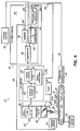
- a fluid dispensing system 20 is comprised of a fluid dispensing gun 22 having a nozzle 24 for dispensing a fluid 26, for example, a hot melt or cold adhesive or glue, onto a part or substrate 28.
- a conveyor 30 carries the substrate 28 past the dispensing gun 22.
- the conveyor 30 is mechanically coupled to a conveyor drive having a conveyor motor 32.
- a conveyor feedback device 34 for example, an encoder, resolver, etc., is mechanically coupled to the conveyor 30 and detects conveyor motion.
- the feedback device 34 has an output 36 providing a feedback signal that changes as a function of changes in the conveyor position. For example, the feedback signal may provide a discrete pulse for each incremental displacement of the conveyor 30.
- a fluid dispensing control 40 has a system control 42 that generally functions to coordinate the operation of the overall fluid dispensing system 20.
- the system control 42 often controls the operation of the conveyor motor 32 and also provides a system user input/output interface (not shown) in a known manner.
- the system control 42 operates in conjunction with a pattern control 44 that controls the operation of the fluid dispensing gun 22 as a function of a particular application and/or part being run.
- the pattern control 44 receives, on an input 46, a part present or trigger signal from a trigger sensor 38.
- the trigger sensor is positioned to detect a feature, for example, a leading edge, of the part 28 moving on the conveyor 30.
- the trigger sensor 38 often provides a signal transition upon detecting the part feature and thus, provides an ability to synchronize other operations with the motion of the part 28 on the conveyor 30.
- the pattern control 44 provides a sequence of gun on/off signals in the form of pulses to a gun control or driver 48 via an input 50.
- each of the gun on/off signals has respective leading and trailing edges representing desired changes in the operating state of the dispensing gun 22.
- the leading edges command or initiate a change of state that turns on or opens the fluid dispensing gun 22, and the trailing edges command or initiate a change of state that turns off or closes the fluid dispensing gun 22.
- the leading and trailing edges of the gun on/off signals from the pattern control 44 represent, respectively, gun on and gun off operating state transitions of the dispensing gun 22.
- a power control 52 within a gun driver 48 is responsive to the gun on/off signals and provides output signals to a dispensing gun coil 54 via an output 56.
- the switching time of the power control 52 is very small when compared to the switching time of the fluid dispensing gun 22; and therefore, for purposes of this invention, the switching time of the power control 52 can be ignored.
- the output signals energize and de-energize the gun coil 54 to operate the dispensing gun 22 as a function of the timing and duration of the gun on/off pulses from the pattern control 44. Thus, the output signals also command or cause the dispensing gun to change states.
- the dispensing valve 60 is fluidly connected to a pump 62; and the pump 62 receives fluid, for example, an adhesive, from a reservoir (not shown). Upon the dispensing valve 60 opening, pressurized adhesive in the dispensing gun 22 passes through the nozzle 24 and is applied to the substrate 28 as a fluid deposit 64, for example, a dot, bead, strip, etc.
- the dispensing valve 60 remains open for the duration of the gun on/off pulse; and in response to the trailing edge of a gun on/off pulse, that is, a gun OFF transition, the gun driver 48 terminates current flow through the gun coil 54.
- the magnetic field around the armature 58 collapses, and the dispensing valve 50 is closed by a return spring (not shown) in a known manner.
- the pattern control 44 has a pattern store and compensator 66 that receives and stores a fluid dispensing pattern from the system control 42 via input 68.
- the fluid dispensing pattern is entered into the system control 42 in a known manner.
- the fluid dispensing pattern represents a series of fluid dispensing cycles associated with a part 28 that result in a desired pattern of fluid deposits 64 thereon.
- the fluid dispensing pattern is often represented by numerical quantities or values in the pattern store 66 that are a measure of distances on the part 28 from a feature such as its leading edge 70 to leading and trailing edges 72, 73, respectively, of a fluid deposit 64.
- a counter 74 within the pattern control 44 is electrically connected to the conveyor feedback device 34 and the trigger sensor 38 and accumulates a numerical value representing motion of the substrate 28 after its leading edge 70 has been detected.
- a comparator 76 is responsive to a first numerical value from the pattern store 66 representing a distance from the leading edge 70 of the substrate 28 to a first leading edge 72a of the first adhesive deposit 64a.
- the comparator 76 is responsive to a second numerical value in the counter 74 representing motion of the substrate 28 after its leading edge 70 has been detected.
- the comparator detects a relationship between those two values, for example, a substantial equality, the comparator 76 provides a gun ON transition from the pattern control 44 to the gun driver 48.
- the gun driver 48 turns on or opens the fluid dispensing gun 22, and fluid is deposited onto the substrate 28.
- the counter 74 continues to count the feedback pulses from the conveyor feedback device 34, and the pattern store 66 presents the next stored value to the comparator.
- That next value determines the time at which the fluid dispensing gun should be turned off and represents the location of the trailing edge 73a of the first fluid deposit 64a as measured from the leading edge 70 of the substrate 28.
- the comparator 76 detects a relationship between those two quantities, for example, a substantial equality, it provides a gun OFF transition to the gun driver 48; and the gun driver 48 causes the fluid dispensing gun 22 to shut off or close, thereby terminating the dispensing of fluid onto the moving substrate 28.
- the fluid dispensing system of Fig. 1 has a compensation system that includes a sensor 80 and a switching time detector 82.
- the sensor 80 is mounted with respect to the conveyor 30 so that the sensor 80 can sense, and provides a sensed or sensor feedback signal representative of, one or more edges 72, 73 of respective adhesive deposits 64 as the conveyor 30 moves the substrate 28.
- the sensor 80 is any sensor capable of reliably providing a high speed indication of the one or more edges 72, 73, for example, an infrared sensor, dielectric sensor, laser sensor, etc.
- the switching time detector 82 has inputs 84, 86 electrically connected to respective outputs of the sensor 80 and the comparator 76 and is used to detect or measure the switching time or delay of the fluid dispensing gun 22.
- the switching time detector input 86 can alternatively be responsive to output 56 of the gun driver 48; however, the signal on the output 56 is a high current signal and therefore, is more difficult to use as a transition reference.
- the detector 82 provides a compensation signal or value representing the detected delay that is used by the pattern store 66 to compensate the numerical values presented to the comparator 76, so that gun ON/OFF transitions are automatically and continuously shifted in real time to eliminate the adverse effects of dispensing gun switching time. Therefore, fluid is more reliably and accurately deposited on the moving substrate 28.
- a user enters a particular pattern of fluid deposits 64 utilizing the system control 42. That pattern is then downloaded via line 68 to the pattern store 66.
- the capability of the pattern control 44 to store one or more patterns over one or more dispensing cycles will depend on the application and the type of fluid dispensing control 40 being utilized.
- the user then, via the system control 42, commands the conveyor motor 32 to start, thereby moving the substrate 28 on the conveyor 30 toward the fluid dispensing gun 22.
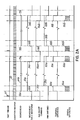
- a trigger signal 87 of Fig. 2A is provided to the counter 74.
- the counter 74 then begins to accumulate pulses 89 from the conveyor feedback device 34 and thus, the counter 74 accumulates a numerical value representing the displacement of the conveyor 30 with respect to the leading edge 70 of the substrate 28.
- the pattern store 66 presents a first numerical value to the comparator 76 representing the distance from the leading edge 70 of the substrate 28 to the leading edge 72a of the first deposit 64a.
- the comparator 76 determines that the substrate 28 has moved through a displacement substantially equal to the first numerical value
- the comparator 76 provides a leading edge of a gun on/off pulse, that is, a gun ON transition to the power control 52.
- the power control 52 provides an output signal that energizes and changes the state of the gun coil 54.
- a leading edge of an output signal from the gun driver 48 creates current flow through the gun coil 54, thereby building up a magnetic field that lifts an armature 58 and a dispensing valve 60 connected thereto.
- a finite time is required to open the dispensing valve 60 and apply a fluid 26 as a leading edge 72a of the deposit 64a on the moving substrate 28.
- the deposit 64a (Fig. 2A) can be represented as a waveform 90a that has respective leading and trailing edges 92a, 94a that correspond to the respective leading and trailing edges 72a, 73a of the fluid deposit 64a. If the fluid dispensing gun switching time were zero, then the gun ON transition 96a would correspond to the leading edge 92a and thus, produce a leading edge 72 of fluid on the substrate 28. However, the delay between the actuation of a dispensing valve 60 and the deposition of the leading edge 72a onto the substrate 28 changes the desired location of the leading edge 72a.
- That delay is detected or measured by the switching time detector 82.
- the sensor 82 Upon detecting the leading edge 72a of the fluid deposit 64a, the sensor 82 provides an edge feedback signal represented by transition 98a to the switching time detector 82.
- the detector 82 is also responsive to the gun ON transition 96a provided by the comparator 76.
- the switching time detector 82 detects or measures a difference or delay between the transitions 96a and 98a. That delay can be represented in a time domain by a pulse 100a or represented in a spatial domain by a count of feedback pulse transitions 102a from the conveyor feedback device 34 occurring between the transitions of the pulse 100a.
- That measured delay or difference represents a real time delay between a command to open the dispensing gun 22 and the deposit of fluid onto the moving substrate 28.
- the measured delay in either of its forms 100a, 102a is provided to the pattern store 66 where it is used to adjust or modify the values representing the desired fluid dispensing pattern.
- a stored pattern value representing the next leading edge 72b of the substrate 64b is compensated by the detected delay 100a, 102a. Therefore, the pattern store 66 presents a numerical value to the comparator 76 that, in essence, advances the location of the leading edge 72b by the measured delay time 100a, 102a. Therefore, the comparator 76 produces a gun ON transition 96b that is advanced by the measured delay 100a, 102a.
- The, current is applied to the dispensing gun coil 54 in advance; and assuming that the gun switching time has not changed appreciably since the prior operation, the sensor 80 detects the leading edge 72b of the fluid deposit 64b at a time represented by the transition 98b.
- the deposition of fluid 26 onto the substrate 28 occurs at its desired time or location as represented by the transition 92b.
- the measured delay 100a, 102a for each gun ON transition is used by the pattern store 66 to compensate a subsequent gun ON transition, thereby depositing or placing the leading edges 72 of subsequent respective fluid deposits 64 to their respective desired locations on the moving substrate 28.
- the initial gun ON transition 96a results in a shift in the location of the leading edge 72a of the fluid deposit 64a from its desired location as represented by the transition 92a to a location represented by the transition 98a.
- the shifted fluid deposit 64a is an example of a poorer quality fluid deposit and may result in a scrap product.
- the user can input, via the system control 42, a fixed compensation value representing an estimate of the switching time of the dispensing gun 22. That initial compensation value C1 is provided to the pattern control 44 via input 104 where it is stored. Further, referring to Fig. 2B, that initial compensation value is utilized by the pattern store 66 to advance the leading edge 72a of the first fluid deposit 64a. Therefore, the comparator 76 provides a gun ON transition 96c that is also advanced by the amount of the initial compensation value C1.
- the advanced gun ON transition 96c results in the edge sensor 80 providing a transition 98c representing the leading edge 72a at a point that is closer to the desired location as represented by the transition 92a.
- the switching time detector 82 provides a pulse 100c representing the time between the transitions 96c and 98c; and as indicated at 102c, that time delay can be represented in terms of encoder pulse transitions.
- the initial leading edge 72a can be placed closer to its desired location.
- the initial compensation value C1 is not equal to the gun switching time.
- the switching time detector 82 measures a delay that does represent the gun switching time; and that delay is used to compensate the next leading edge 72b as earlier described.
- Figs. 2A and 2B provide a compensation for leading edges 72 of fluid deposits 64 arising from variations in the dispensing gun switching time.
- the sensor 80, switching time detector 82 and pattern store 66 can be used to provide a similar compensation to the gun OFF transition so that the trailing edges 73 of respective deposits 64 are precisely located on the moving substrate 28.
- an initial gun OFF transition 106a is provided at a time representing the desired location of the trailing edge as represented by the transition 94a.
- the sensor 80 Upon detecting the trailing edge 73a on the moving substrate 28, the sensor 80 provides a feedback signal represented by the edge 108a.
- the switching time detector 80 measures the turn off delay of the fluid dispenser 22 and provides a delay signal to the pattern store 66 as represented by the waveforms 110a, 112a.
- the pattern store 66 then compensates the next trailing edge 73b by compensating or advancing the numerical value representing the trailing edge 73b stored therein.
- the comparator advances the gun OFF transition 106b by an amount substantially equal to the measured delay 1101, 112a. Therefore, assuming the switching time has not changed, the sensor 80 detects an occurrence of the trailing edge 73b at a time corresponding to its desire location. Thus, the sensor 80 produces an edge feedback signal represented by the transition 108b that corresponds to the desired edge location as represented by transition 94b.
- the initial trailing edge 108a is shifted from its desired position as represented by the transition 94a. Therefore, referring to Fig. 2B, a user defined and input fixed compensation value C2 can be used to provide an initial compensation for the trailing edge 73a.
- the gun OFF transition 106c is advanced by the magnitude of the initial compensation C2, and the resulting trailing edge is placed at a location closer to the position 94a as represented by the transition 108c.
- the measured delay as represented by the waveforms 110c, 112c accounts for the full turn off switching time of the dispensing gun 22, so that the subsequent trailing edge 73b is placed at its desired location as represented by the transition 108b.
- the turn-on and turn-off switching times may be substantially equal, and therefore, the gun on switching time can be used to compensate the gun OFF transition.
- the measured delay in turning the dispensing gun off may be used to compensate the gun ON transition.
- the turn on switching time will be substantially different from the turn off switching time.
- the pattern store 66 is used to separately store the turn on and turn off switching times or delays. With any of the embodiments, during production runs, any changes caused by a drifting of the switching times, may be used to compensate the gun ON and gun OFF transitions as appropriate.
- a gun actuation or switching sensor 130 may be used to detect the mechanical actuation of the dispensing valve 60 in switching from its off state to its on state.
- the gun actuation sensor 130 may be implemented using an accelerometer, for example, that detects motion of the armature 58 and/or valve stem (not shown) connected to the armature 58 within the dispensing valve 60.
- the armature moves through a short linear stroke.
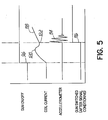
- the gun actuation sensor 130 Upon the magnetic field causing the armature to move, the gun actuation sensor 130 provides a sensed or sensor feedback signal to an input 84 of the switching time detector 82 as represented by the waveform 114 of Fig. 5.
- the output from the gun actuation sensor 130 drops rapidly back to its initial state.
- Signal conditioning in the gun actuation sensor 130 or the switching time detector may use a peak detector to detect the maximum amplitude of the waveform 114 (Fig. 5).
- the peak value of the waveform 114 occurs instantaneously before the armature 58 reaches the end of its stroke.
- the peak value of the accelerometer signal in essence detects when the dispensing valve is open.
- Further signal conditioning can be used to create a transition 116.
- the switching time detector 82 in a manner similar to that described before, detects or measures the delay between the initiation of the gun on signal from the comparator 76 and the occurrence of the transition 116.
- That delay is used by the pattern store 66 to adjust or compensate the values representing the leading and/or trailing edges 72, 73 of the fluid deposit 64 and hence, the occurrence of the gun ON/gun OFF transitions.
- the gun actuation sensor can be used to measure a delay caused by the fluid dispensing gun 22 being switched from its on state to its off state.
- many gun drivers 48 contain a current sensor 134 that provides a sensed current feedback signal representing current flow in the coil.
- the current feedback signal from the sensor 134 is often provided to the power control 52 of the gun driver 48 for current control purposes.
- the current feedback signal is also provided to a signal conditioner 136 that, in turn, is connected to the input 84 of the switching time detector 82.
- the current in the coil 54 has a unique waveform 118 (Fig. 5) in which the magnitude of the current reaches a peak 120 and then drops to a null 122 before increasing again.
- the null 122 in current magnitude is caused by the magnetic field pulling the armature 58 away from a pole (not shown).
- the separation of the armature 58 from the pole effectively changes the inductance of the coil 54, thereby producing the null 122.
- the signal conditioner 136 often provides some filtering and in addition, detects the null 122 and provides a transition as represented by the transition 116.
- the signal condition may be provided in the switching time detector 82.
- the null 122 can be detected in any appropriate manner. However, in one embodiment, the derivative of the current feedback signal can be continuously monitored, and the null 122 is represented by a second occurrence of a zero value of that derivative.
- the fluid dispensing system 20 continuously monitors the switching time of the fluid dispensing gun and automatically adjusts the operation of the gun driver 48 in real time, so that fluid is accurately dispensed onto the moving substrate 28.
- This consistency in the fluid dispensing process reliably provides a high quality finished product.
- the capability of automatically measuring and compensating of variations in the switching time of the fluid dispensing gun also permits a wider variety of fluid dispensing guns to be used to accurately dispense fluid onto a moving substrate. For example, with the compensation described herein, fluid dispensing guns having slower gun switching times can be used to more accurately dispense fluid onto a moving substrate. In some applications, low voltage solenoid-operated guns can be considered for use when such was not possible without the compensation system described herein. This advantage is significant because slower switching, low voltage fluid dispensing guns are often less expensive.
- the compensation system described herein has a further advantage in that it allows more flexibility in connecting a particular pattern control with different gun drivers. Further, since the compensation system provides more flexibility to a pattern control and gun driver combination, it is now feasible to integrate the design of a pattern control and gun driver into a single unit.
- a still further advantage of the compensation system herein is that it is no longer necessary to design fluid dispensing guns having shorter and shorter switching times in order to adapt to ever increasing conveyor speeds.
- the capability of quantifying in real time gun switching time is also a useful input to diagnostic and quality control systems.
- the capability of a switching time compensation system to continuously adjust the fluid dispensing process in real time presents unique opportunities to improve the quality and economy of a fluid dispensing process.
- the switching time detector is located in pattern control 44; however, as will be appreciated, in an alternative embodiment, the switching time detector may be integrated into the gun driver 48 or any other part of the system control 40.
- the frequency of computation of the compensation signal or value and adjustment of the signals from the control system 40 is not specified.
- the frequency of signal adjustments can vary from application to application.
- a compensation value can be computed and an output signal from the gun driver 48 adjusted with each change of state of the fluid dispensing gun 22.
- the output signal from the gun driver can be adjusted at a different rate than the determination of compensation values.
- the determination of compensation values and/or adjustment of output signals can occur after timed periods, after measured conveyor displacements, after a number of dispensing cycles, etc.
- the output signals may be adjusted only after detecting a particular magnitude of change in the compensation value.
- the examples used result in the gun ON/OFF transition and corresponding output signals being advanced in time.
- environmental or other changes in the operation of the dispensing gun may result in the gun switching time in one fluid dispensing cycle decreasing from what it was in a prior dispensing cycle.
- the gun ON/OFF transition and output signal from the gun driver 48 are adjusted in an opposite direction or retarded in time in response to the compensation signal.
- each embodiment has a sensor providing a sensor feedback signal that can be used to compensate for the dispensing gun switching time in turning the dispensing gun on and off.
- each sensor has its benefits and drawbacks.
- a coil current sensor 134 is used to provide a feedback signal with which the compensation value is determined.
- a current sensor may prove satisfactory in determining a dispensing gun ON switching time because the coil current causes the dispensing valve to open.
- the dispensing valve is often closed by a return spring; and in those applications, current sensing may be less reliable. It is within the scope of the claimed invention to use different and multiple sensors to detect a changes of state of the dispensing gun 22 where each sensor is particularly suited to detect a particular change of state.
- a first advantageous embodiment comprises a sensor producing a sensor feedback signal in response to the fluid dispensing gun changing operating states and a control which is connected to the sensor.
- the control provides first signals causing the fluid dispensing gun to change operating states.
- the control comprises a detector responsive to one of said first signals and the sensor feedback signal for producing a compensation signal representing a difference between an occurrence of said one of said first signals and an occurrence of said sensor feedback signal. Said control adjusts a subsequent first signal in response to said compensation signal.
- each of the above mentioned first signals has a leading edge initiating a change of state of the fluid dispensing gun.
- the control can adjust the leading edge of one of said first signals in response to the compensation signal.
- each of the mentioned first signals has a trailing edge initiating a change of state of the fluid dispensing gun
- the control can be used to adjust the trailing edge of one of said first signals in response to the compensation signal.
- the senor produces the sensor feedback signal in response to sensing a presence of a fluid deposited on the substrate by the fluid dispensing gun.
- the senor produces the feedback signal in response to sensing a leading edge of a fluid deposited on the substrate by the fluid dispensing gun or
- the sensor may produce the feedback signal in response to motion of the armature causing a change of operating state of the fluid dispensing gun.
- the armature is connected to a dispensing valve
- the sensor may produce the feedback signal in response to a change in current flow in the coil representing a change of operating state of the fluid dispensing gun.
- control advantageously comprises further a conveyor feedback device providing a series of pulses, each pulse representing an incremental displacement of the conveyor.
- the control provides the compensation signal as a number of pulses representing a difference between an occurrence of said one of said first signals and an occurrence of said sensor feedback signal.
- the displacement of the conveyor during the switching time of the fluid dispensing gun can be used as compensation signal.
- the fluid dispensing gun is operated by a coil and requires a switching time to change operating states
- the control is connected to the coil so that it provides a first signal generating a change in current flow in the coil causing the fluid dispensing gun to change operating states.
- the control comprises a current sensor providing a sensor feedback signal in response to detecting the current flow in the coil, and a detector responsive to said first signal and said sensor feedback signal for producing a compensation signal representing the switching time of the fluid dispensing gun.
- the control is then used for adjusting an occurrence of a subsequent first signal in response to said compensation signal to compensate a subsequent change of operating state of the fluid dispensing gun for the switching time of the fluid dispensing gun.
- an apparatus for operating a fluid dispensing gun dispensing a pattern of fluid deposits onto a substrate supported on a conveyor moving relative to the dispensing gun, the dispensing gun requiring a switching time to change operating states, comprising a sensor producing a sensor feedback signal in response to the fluid dispensing gun changing operating states and a control.
- the control stores representations of the pattern of fluid deposits on the substrate and is capable of producing a gun ON transition commanding the fluid dispenser to open and dispense fluid onto the substrate.
- It comprises a detector responsive to said sensor feedback signal and said gun ON transition for providing a compensation signal representing a difference between an occurrence of said sensor feedback signal and said gun ON transition and adjusts an occurrence of a subsequent gun ON transition to compensate for the switching time of the fluid dispensing gun
- the above mentioned apparatus can comprise a control which is capable of producing a gun OFF transition commanding the fluid dispenser to close and cease dispensing fluid onto the substrate.
- the control provides a compensation signal representing a difference between an occurrence of the sensor feedback signal and the gun OFF transition. It adjusts an occurrence of a subsequent gun OFF transition to compensate for the switching time of the fluid dispensing gun.
- a preferred method of operating a fluid dispensing gun to dispense a fluid onto a substrate moving relative to the dispensing gun, the dispensing gun changing from a first operating state to a second operating state in response to a signal from a fluid dispensing control comprises applying a first signal to the dispensing gun commanding a change from the first operating state to the second operating state, detecting a change from the first operating state to the second operating state of the fluid dispensing gun, detecting a difference in time between an application of the first signal and detecting the change from the first operating state to the second operating state of the fluid dispensing gun, and adjusting in response to the difference in time an application of a successive signal commanding a change from the first operating state to the second operating state of the dispensing gun.
- the method described above may preferably include the first signal to command the dispensing gun to open and further comprise determining a difference between an application of the first signal to the fluid dispensing gun and a detection of the physical characteristic in response thereto.
- the method described above may preferably further comprise detecting a change in the current caused by an opening of the fluid dispensing gun.
- the method described above wherein the first signal commands the dispensing gun to close may preferably further comprise detecting a physical characteristic produced by the dispensing gun closing, determining a difference between an application of the first signal to the fluid dispensing gun and a detection of the physical characteristic in response thereto.
- the embodiment may further comprise detecting a feature of a fluid deposit applied to the moving substrate in response to the dispensing gun closing.
- the embodiment further comprises detecting a motion of the armature to close the fluid dispensing gun.
- the embodiment may further comprise detecting a change in the current caused by a closing of the fluid dispensing gun.
Landscapes
- Coating Apparatus (AREA)
- Spray Control Apparatus (AREA)
- Application Of Or Painting With Fluid Materials (AREA)
Applications Claiming Priority (2)
| Application Number | Priority Date | Filing Date | Title |
|---|---|---|---|
| US09/999,058 US6849130B2 (en) | 2001-10-31 | 2001-10-31 | Fluid dispenser with automatic compensation and method |
| US999058 | 2001-10-31 |
Publications (2)
| Publication Number | Publication Date |
|---|---|
| EP1308216A2 true EP1308216A2 (fr) | 2003-05-07 |
| EP1308216A3 EP1308216A3 (fr) | 2005-05-18 |
Family
ID=25545845
Family Applications (1)
| Application Number | Title | Priority Date | Filing Date |
|---|---|---|---|
| EP02024451A Withdrawn EP1308216A3 (fr) | 2001-10-31 | 2002-10-29 | Distributeur de fluide à compensation automatique et son procédé d'utilisation |
Country Status (3)
| Country | Link |
|---|---|
| US (2) | US6849130B2 (fr) |
| EP (1) | EP1308216A3 (fr) |
| JP (1) | JP2003181339A (fr) |
Cited By (3)
| Publication number | Priority date | Publication date | Assignee | Title |
|---|---|---|---|---|
| EP1647194A1 (fr) * | 2004-10-14 | 2006-04-19 | Soremartec S.A. | Procédé et machine déposant une couche décorative sur des produits alimentaires |
| WO2017044685A1 (fr) | 2015-09-11 | 2017-03-16 | Henkel IP & Holding GmbH | Système de surveillance adhésif à distance |
| US10646893B2 (en) | 2015-08-31 | 2020-05-12 | Nordson Corporation | Automatic piezo stroke adjustment |
Families Citing this family (15)
| Publication number | Priority date | Publication date | Assignee | Title |
|---|---|---|---|---|
| WO2005079996A1 (fr) * | 2004-02-23 | 2005-09-01 | Abb K.K. | Dispositif de peinture avec tête de pulvérisation par atomisation |
| US7364775B2 (en) * | 2004-11-09 | 2008-04-29 | Nordson Corporation | Closed loop adhesive registration system |
| US20070039931A1 (en) * | 2005-08-17 | 2007-02-22 | Vancho Naumovski | Applicating assembly for weld material and method of applying weld material |
| US20070069041A1 (en) * | 2005-09-27 | 2007-03-29 | Nordson Corporation | Viscous material dispensing systems with parameter monitoring and methods of operating such systems |
| US20080271416A1 (en) * | 2007-05-03 | 2008-11-06 | Weyerhaeuser Co. | Sealer applicator for a fiberboard assembler |
| GB0919059D0 (en) * | 2009-10-30 | 2009-12-16 | Sencon Europ Ltd | Application and inspection system |
| EP2353731A1 (fr) * | 2010-01-27 | 2011-08-10 | Robatech AG | Buse d'application électrique destinée à déposer un produit fluide et dispositif doté d'une telle buse d'application électrique |
| CN105903646B (zh) * | 2016-05-11 | 2018-01-12 | 玖龙包装(太仓)有限公司 | 分开计量瓦楞机各机台用胶量的实时计量方法 |
| CN105921377B (zh) * | 2016-06-21 | 2019-08-30 | 乌兰察布市集宁区泰吉电子科技有限公司 | 一种一站式自动化点胶方法 |
| CN206382185U (zh) * | 2017-01-13 | 2017-08-08 | 合肥鑫晟光电科技有限公司 | 一种用于点胶设备的滴胶装置 |
| US12384302B2 (en) | 2018-08-06 | 2025-08-12 | East Mountain Outfitters Llc | Bicycle carrier with damper |
| WO2020033256A1 (fr) | 2018-08-06 | 2020-02-13 | East Mountain Outfitters Llc | Support de bicyclette et râtelier de stockage de bicyclette |
| CN109332077A (zh) * | 2018-09-29 | 2019-02-15 | 天津七所高科技有限公司 | 一种自动抹胶系统 |
| CN115176084A (zh) | 2020-02-28 | 2022-10-11 | 伊利诺斯工具制品有限公司 | 活塞监测组件 |
| US20250018418A1 (en) * | 2023-07-11 | 2025-01-16 | King Wooma Industrial Co., Ltd. | Glue Applying Machine |
Family Cites Families (5)
| Publication number | Priority date | Publication date | Assignee | Title |
|---|---|---|---|---|
| DE3713999A1 (de) * | 1987-04-27 | 1988-11-10 | Behr Industrieanlagen | Verfahren zum selbsttaetigen serienweisen beschichten von werkstuecken |
| CA2095555A1 (fr) * | 1992-12-16 | 1994-06-17 | Robert L. Popp | Appareil et methodes de controle selectif de pulverisation d'un liquide |
| JP2948543B2 (ja) * | 1996-11-26 | 1999-09-13 | 三菱重工業株式会社 | グルーガン式糊付装置 |
| DE19824007A1 (de) * | 1998-05-29 | 1999-12-02 | Topack Verpacktech Gmbh | Verfahren und Vorrichtung zum Setzen von Leimstellen auf taktweise transportierte Objekte |
| US6401976B1 (en) * | 2000-03-23 | 2002-06-11 | Nordson Corporation | Electrically operated viscous fluid dispensing apparatus and method |
-
2001
- 2001-10-31 US US09/999,058 patent/US6849130B2/en not_active Expired - Fee Related
-
2002
- 2002-10-29 EP EP02024451A patent/EP1308216A3/fr not_active Withdrawn
- 2002-10-31 JP JP2002317608A patent/JP2003181339A/ja not_active Withdrawn
-
2005
- 2005-01-14 US US11/036,425 patent/US20050121460A1/en not_active Abandoned
Non-Patent Citations (1)
| Title |
|---|
| None |
Cited By (7)
| Publication number | Priority date | Publication date | Assignee | Title |
|---|---|---|---|---|
| EP1647194A1 (fr) * | 2004-10-14 | 2006-04-19 | Soremartec S.A. | Procédé et machine déposant une couche décorative sur des produits alimentaires |
| US10646893B2 (en) | 2015-08-31 | 2020-05-12 | Nordson Corporation | Automatic piezo stroke adjustment |
| WO2017044685A1 (fr) | 2015-09-11 | 2017-03-16 | Henkel IP & Holding GmbH | Système de surveillance adhésif à distance |
| KR20180053304A (ko) * | 2015-09-11 | 2018-05-21 | 헨켈 아이피 앤드 홀딩 게엠베하 | 원격 접착제 모니터링 시스템 |
| CN108139717A (zh) * | 2015-09-11 | 2018-06-08 | 汉高知识产权控股有限责任公司 | 粘合剂的远程监控系统 |
| EP3347774A4 (fr) * | 2015-09-11 | 2019-05-08 | Henkel IP & Holding GmbH | Système de surveillance adhésif à distance |
| US10421097B2 (en) | 2015-09-11 | 2019-09-24 | Henkel Ag & Co. Kgaa | Remote adhesive monitoring system |
Also Published As
| Publication number | Publication date |
|---|---|
| US20050121460A1 (en) | 2005-06-09 |
| US20030080159A1 (en) | 2003-05-01 |
| US6849130B2 (en) | 2005-02-01 |
| EP1308216A3 (fr) | 2005-05-18 |
| JP2003181339A (ja) | 2003-07-02 |
Similar Documents
| Publication | Publication Date | Title |
|---|---|---|
| US6849130B2 (en) | Fluid dispenser with automatic compensation and method | |
| US7954451B2 (en) | Closed loop adhesive registration system | |
| US6517891B1 (en) | Control system for metering pump and method | |
| US7083823B2 (en) | Monitoring system and method for fluid dispensing system | |
| US5174472A (en) | Control system for timing a sequence of events | |
| US8334023B2 (en) | Methods for regulating the placement of fluid dispensed from an applicator onto a workpiece | |
| US8365952B2 (en) | Compensating pressure controller for fluid dispenser and method | |
| CA2413895A1 (fr) | Pompe | |
| US4957782A (en) | Method for automatic sequential coating of workpieces | |
| US5319568A (en) | Material dispensing system | |
| US4500937A (en) | Control circuit for a solenoid driver for a dispenser | |
| AU701788B2 (en) | Improved electric gun driver | |
| CA1331045C (fr) | Methode de positionnement de noyau-plongeur de solenoide | |
| MXPA03002781A (es) | Dispositivo para aplicar adhesivo a una pieza de trabajo. | |
| US6688580B2 (en) | Adjustable die for a fluid dispenser and method | |
| KR20010024174A (ko) | 유체분배시스템 | |
| JPH10244211A (ja) | 塗布パターンの位置ずれを検知する方法及びその補正方法 | |
| US5570621A (en) | Adaptive control for hydraulic systems | |
| US20050244569A1 (en) | Automatic tolerance determination system for material application inspection operation | |
| CN1149131C (zh) | 在按节拍输送的物体上设置涂胶点的方法和装置 | |
| US4838311A (en) | Control system for a programmed spraying device | |
| US5922132A (en) | Automated adhesive spray timing control | |
| JPH05285434A (ja) | 液体吐出装置 | |
| JP2012045476A (ja) | 高粘性流体の定量塗布における吐出量制御方法及び装置 | |
| JPH07256163A (ja) | エアレス自動塗装装置 |
Legal Events
| Date | Code | Title | Description |
|---|---|---|---|
| PUAI | Public reference made under article 153(3) epc to a published international application that has entered the european phase |
Free format text: ORIGINAL CODE: 0009012 |
|
| AK | Designated contracting states |
Designated state(s): AT BE BG CH CY CZ DE DK EE ES FI FR GB GR IE IT LI LU MC NL PT SE SK TR |
|
| AX | Request for extension of the european patent |
Extension state: AL LT LV MK RO SI |
|
| PUAL | Search report despatched |
Free format text: ORIGINAL CODE: 0009013 |
|
| AK | Designated contracting states |
Kind code of ref document: A3 Designated state(s): AT BE BG CH CY CZ DE DK EE ES FI FR GB GR IE IT LI LU MC NL PT SE SK TR |
|
| AX | Request for extension of the european patent |
Extension state: AL LT LV MK RO SI |
|
| 17P | Request for examination filed |
Effective date: 20050916 |
|
| AKX | Designation fees paid |
Designated state(s): DE ES FR GB IT |
|
| 17Q | First examination report despatched |
Effective date: 20061123 |
|
| STAA | Information on the status of an ep patent application or granted ep patent |
Free format text: STATUS: THE APPLICATION IS DEEMED TO BE WITHDRAWN |
|
| 18D | Application deemed to be withdrawn |
Effective date: 20070404 |