EP1308377A1 - Véhicule à chenilles - Google Patents
Véhicule à chenilles Download PDFInfo
- Publication number
- EP1308377A1 EP1308377A1 EP02020940A EP02020940A EP1308377A1 EP 1308377 A1 EP1308377 A1 EP 1308377A1 EP 02020940 A EP02020940 A EP 02020940A EP 02020940 A EP02020940 A EP 02020940A EP 1308377 A1 EP1308377 A1 EP 1308377A1
- Authority
- EP
- European Patent Office
- Prior art keywords
- tracked vehicle
- braking
- brake
- vehicle according
- pressure
- Prior art date
- Legal status (The legal status is an assumption and is not a legal conclusion. Google has not performed a legal analysis and makes no representation as to the accuracy of the status listed.)
- Granted
Links
- 230000033001 locomotion Effects 0.000 claims description 21
- 238000012544 monitoring process Methods 0.000 claims description 12
- 230000001419 dependent effect Effects 0.000 claims description 5
- 230000008859 change Effects 0.000 claims description 3
- 230000008878 coupling Effects 0.000 claims description 3
- 238000010168 coupling process Methods 0.000 claims description 3
- 238000005859 coupling reaction Methods 0.000 claims description 3
- 238000005096 rolling process Methods 0.000 claims description 3
- 238000006243 chemical reaction Methods 0.000 claims description 2
- 238000002485 combustion reaction Methods 0.000 description 5
- 230000007257 malfunction Effects 0.000 description 5
- 230000005540 biological transmission Effects 0.000 description 4
- 238000000034 method Methods 0.000 description 4
- 230000008569 process Effects 0.000 description 4
- 230000001133 acceleration Effects 0.000 description 3
- 230000006835 compression Effects 0.000 description 3
- 238000007906 compression Methods 0.000 description 3
- 238000010586 diagram Methods 0.000 description 3
- 239000003638 chemical reducing agent Substances 0.000 description 2
- 230000001276 controlling effect Effects 0.000 description 2
- 230000002950 deficient Effects 0.000 description 2
- 238000005086 pumping Methods 0.000 description 2
- 238000012546 transfer Methods 0.000 description 2
- 230000009471 action Effects 0.000 description 1
- 230000004913 activation Effects 0.000 description 1
- 230000015556 catabolic process Effects 0.000 description 1
- 238000013461 design Methods 0.000 description 1
- 238000011156 evaluation Methods 0.000 description 1
- 239000010720 hydraulic oil Substances 0.000 description 1
- 238000012423 maintenance Methods 0.000 description 1
- 230000001105 regulatory effect Effects 0.000 description 1
- 230000001960 triggered effect Effects 0.000 description 1
Images


Classifications
-
- B—PERFORMING OPERATIONS; TRANSPORTING
- B62—LAND VEHICLES FOR TRAVELLING OTHERWISE THAN ON RAILS
- B62D—MOTOR VEHICLES; TRAILERS
- B62D5/00—Power-assisted or power-driven steering
- B62D5/001—Mechanical components or aspects of steer-by-wire systems, not otherwise provided for in this maingroup
- B62D5/003—Backup systems, e.g. for manual steering
-
- B—PERFORMING OPERATIONS; TRANSPORTING
- B60—VEHICLES IN GENERAL
- B60T—VEHICLE BRAKE CONTROL SYSTEMS OR PARTS THEREOF; BRAKE CONTROL SYSTEMS OR PARTS THEREOF, IN GENERAL; ARRANGEMENT OF BRAKING ELEMENTS ON VEHICLES IN GENERAL; PORTABLE DEVICES FOR PREVENTING UNWANTED MOVEMENT OF VEHICLES; VEHICLE MODIFICATIONS TO FACILITATE COOLING OF BRAKES
- B60T11/00—Transmitting braking action from initiating means to ultimate brake actuator without power assistance or drive or where such assistance or drive is irrelevant
- B60T11/10—Transmitting braking action from initiating means to ultimate brake actuator without power assistance or drive or where such assistance or drive is irrelevant transmitting by fluid means, e.g. hydraulic
- B60T11/16—Master control, e.g. master cylinders
- B60T11/20—Tandem, side-by-side, or other multiple master cylinder units
- B60T11/21—Tandem, side-by-side, or other multiple master cylinder units with two pedals operating on respective circuits, pressures therein being equalised when both pedals are operated together, e.g. for steering
-
- B—PERFORMING OPERATIONS; TRANSPORTING
- B60—VEHICLES IN GENERAL
- B60T—VEHICLE BRAKE CONTROL SYSTEMS OR PARTS THEREOF; BRAKE CONTROL SYSTEMS OR PARTS THEREOF, IN GENERAL; ARRANGEMENT OF BRAKING ELEMENTS ON VEHICLES IN GENERAL; PORTABLE DEVICES FOR PREVENTING UNWANTED MOVEMENT OF VEHICLES; VEHICLE MODIFICATIONS TO FACILITATE COOLING OF BRAKES
- B60T17/00—Component parts, details, or accessories of power brake systems not covered by groups B60T8/00, B60T13/00 or B60T15/00, or presenting other characteristic features
- B60T17/18—Safety devices; Monitoring
- B60T17/20—Safety devices operable by passengers other than the driver, e.g. for railway vehicles
-
- B—PERFORMING OPERATIONS; TRANSPORTING
- B60—VEHICLES IN GENERAL
- B60T—VEHICLE BRAKE CONTROL SYSTEMS OR PARTS THEREOF; BRAKE CONTROL SYSTEMS OR PARTS THEREOF, IN GENERAL; ARRANGEMENT OF BRAKING ELEMENTS ON VEHICLES IN GENERAL; PORTABLE DEVICES FOR PREVENTING UNWANTED MOVEMENT OF VEHICLES; VEHICLE MODIFICATIONS TO FACILITATE COOLING OF BRAKES
- B60T8/00—Arrangements for adjusting wheel-braking force to meet varying vehicular or ground-surface conditions, e.g. limiting or varying distribution of braking force
-
- B—PERFORMING OPERATIONS; TRANSPORTING
- B62—LAND VEHICLES FOR TRAVELLING OTHERWISE THAN ON RAILS
- B62D—MOTOR VEHICLES; TRAILERS
- B62D11/00—Steering non-deflectable wheels; Steering endless tracks or the like
- B62D11/02—Steering non-deflectable wheels; Steering endless tracks or the like by differentially driving ground-engaging elements on opposite vehicle sides
- B62D11/06—Steering non-deflectable wheels; Steering endless tracks or the like by differentially driving ground-engaging elements on opposite vehicle sides by means of a single main power source
- B62D11/08—Steering non-deflectable wheels; Steering endless tracks or the like by differentially driving ground-engaging elements on opposite vehicle sides by means of a single main power source using brakes or clutches as main steering-effecting means
-
- B—PERFORMING OPERATIONS; TRANSPORTING
- B62—LAND VEHICLES FOR TRAVELLING OTHERWISE THAN ON RAILS
- B62D—MOTOR VEHICLES; TRAILERS
- B62D11/00—Steering non-deflectable wheels; Steering endless tracks or the like
- B62D11/02—Steering non-deflectable wheels; Steering endless tracks or the like by differentially driving ground-engaging elements on opposite vehicle sides
- B62D11/06—Steering non-deflectable wheels; Steering endless tracks or the like by differentially driving ground-engaging elements on opposite vehicle sides by means of a single main power source
- B62D11/10—Steering non-deflectable wheels; Steering endless tracks or the like by differentially driving ground-engaging elements on opposite vehicle sides by means of a single main power source using gearings with differential power outputs on opposite sides, e.g. twin-differential or epicyclic gears
- B62D11/14—Steering non-deflectable wheels; Steering endless tracks or the like by differentially driving ground-engaging elements on opposite vehicle sides by means of a single main power source using gearings with differential power outputs on opposite sides, e.g. twin-differential or epicyclic gears differential power outputs being effected by additional power supply to one side, e.g. power originating from secondary power source
- B62D11/18—Steering non-deflectable wheels; Steering endless tracks or the like by differentially driving ground-engaging elements on opposite vehicle sides by means of a single main power source using gearings with differential power outputs on opposite sides, e.g. twin-differential or epicyclic gears differential power outputs being effected by additional power supply to one side, e.g. power originating from secondary power source the additional power supply being supplied hydraulically
- B62D11/183—Control systems therefor
-
- B—PERFORMING OPERATIONS; TRANSPORTING
- B62—LAND VEHICLES FOR TRAVELLING OTHERWISE THAN ON RAILS
- B62D—MOTOR VEHICLES; TRAILERS
- B62D55/00—Endless track vehicles
- B62D55/06—Endless track vehicles with tracks without ground wheels
Definitions
- the invention relates to a tracked vehicle with a drive system that Driving, braking, direction change and steering functions dependent of corresponding control commands from an electronic control unit performs.
- Such a tracked vehicle is for use on snow slopes generally known by corresponding snow groomers of the applicant.
- Such a known tracked vehicle is with a left as well provided with a right landing gear side, each with a chain drive exhibit.
- Every chain drive is driven by drive hydraulics, which has a hydraulic pump unit for each chassis side.
- the two hydraulic pump units are interposed a transfer case driven by an internal combustion engine, which can be designed as a diesel or gasoline engine.
- Every chain drive is assigned at least one drive wheel, each by a Hydromotor is driven, which is part of the drive hydraulics.
- Steering operations Acceleration and braking processes as well as changes of direction of travel due to switching from forward to The return trip is carried out by correspondingly different controls the hydraulic motors for the chain drives on both sides of the vehicle.
- the left and right side Chain drives can achieve steering movements.
- the control the hydraulic motors are made using corresponding hydraulic control means, which in turn is controlled by an electronic central control unit become.
- the object of the invention is a tracked vehicle of the type mentioned kind of creating that in the event of a failure or malfunction of the electronic control unit nevertheless controls the tracked vehicle allows.
- At least one currentless, separate braking system is provided, which in the case of exceeding or falling below at least one limit value of a function parameter the drive system by at least one currentless control element can be put into function.
- the braking system ensures that even in the event of an electronic failure, an electronic shutdown or an electronics malfunction or a vehicle controller, in particular braking to a standstill is possible. If that Drive system of the tracked vehicle has drive hydraulics, so is the function parameter in particular the pressure within the corresponding hydraulic circuit is decisive. Depending on Functional purpose, it is possible to set one or more pressure limits define above or below which the braking system passes the corresponding priority control is inevitably put into operation becomes.
- a suitable control element is for the hydraulic version
- the control element for the hydraulic version is pressure-dependent switching hydraulic valve.
- the braking system is at least one Function monitoring means assigned. Because the separate braking system not at all during normal operation of the tracked vehicle would be used, a failure of the brake system would not be without more can be recognized.
- the function monitoring means are for this provided to ensure that if the level is exceeded or fallen below corresponding limit values the safe functionality of the Brake system is given.
- the braking system preferably has Both sides of the vehicle have braking devices that are different Activation and consequently also enable steering processes.
- the braking system is at least one control element depending on exceeding or falling below different limit values of the function parameter from its idle mode in a steering function mode or in a braking function mode transferable. It is especially for the steering function mode necessary that the two vehicle sides of the tracked vehicle through the braking system can be controlled differently. This is preferable each vehicle side has its own braking device.
- the braking function mode is particularly necessary when the Braking force of a corresponding braking function of the drive system in itself no longer sufficient, in particular to meet the requirements one by a strong brake pedal pressure of a driver of the Track vehicle triggered brake pressure to meet.
- a steering function mode is particularly necessary in the event of vehicle electronics failure, in order to still be able to control the tracked vehicle.
- the drive system for Steering functions through electronic conversion of tax movements a manually operated control handle using the electronic Control unit is controllable
- the control handle is a mechanical effective coupling link assigned in the event of failure of the electronic Control unit can be activated by a positive actuator and the Control connection of the control handle to the drive system and / or the separate braking system. Since in this embodiment pure electronic transmission of control commands between the Control handle and the drive system is provided must be guaranteed be that the tracked vehicle even if the Electronics remains controllable. Thanks to the switchable mechanical coupling between the manually operated control handle and the drive system or the separate braking system are steering movements to achieve the tracked vehicle.
- each side of the undercarriage is independent of the drive hydraulics Brake device assigned, via at least one separate power supply circuit is fed, and the control handle is mechanical with at least one control element of the energy supply circuit connected, depending on a failure of the electronic Control unit can be switched on by means of a de-energized positive actuator and is dependent on corresponding steering movements
- Control handle controls the braking devices on both sides of the chassis.
- the energy supply circuit for the respective, from the drive hydraulics independent braking device can be electric, pneumatic or be designed hydraulically. Of course they are too Brake devices in a corresponding manner, electrically, pneumatically or integrated hydraulically.
- a hydraulic circuit is provided, which is fed by a pump device is that mechanically in connection with at least one chassis side stands that by the rolling motion of the tracked vehicle the Pump device is supplied with sufficient feed pressure. This ensures that there is sufficient supply pressure is that enables actuation of the brake system.
- the pumping device is dragged along with it, so with suitable coordination the at least one pump device on the brake system the desired feed pressure can be maintained.
- a pressure control valve is used as the control element provided that is proportional to the steering movements of the Control handle a control of both hydraulic circuits and the associated Makes braking devices. This is when driving straight ahead the pressure in both hydraulic circuits is kept the same. At a corresponding steering movement, the pressure in each hydraulic circuit lowered compared to the other hydraulic circuit, so that the desired braking device an appropriate braking function can perform, reducing the intended speed of the respective chain drive is effected.
- each braking device has a mechanically effective brake, in particular a multi-disc brake, that acts on a sprocket on the respective chassis side.
- This multi-disc brake is preferably with two brake pistons or brake discs provided independently can be controlled and each on a corresponding plate pack act.
- a function monitoring means at least one pressure sensor in the at least one energy supply circuit which integrates at least one braking device, which is connected to the electronic control unit.
- a hydraulic circuit is provided in this embodiment.
- function monitoring means the at least one energy supply circuit at least a pressure-dependent switchable actuator and the positive actuator a position sensor assigned to the electronic control unit are connected. This is the monitoring of the functionality of the braking system.
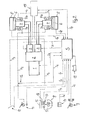
- a tracked vehicle K according to FIG. 1 is on two opposite vehicle sides each provided with a chain drive T.
- Each chain drive T has a revolving chain or caterpillar, which by a sprocket A is driven.
- the two chain drives T are each part of a chassis side.
- each chassis side has one Drive hydraulics described in more detail below, which are part of a Drive system in the sense of the invention and each on the as Driving wheel serving sprocket A acts on each chassis side.
- the Drive hydraulics for each chassis side have a hydraulic motor 4 on which by means of a gear 5 the sprocket A of the assigned Chain drive T drives.
- the drive hydraulics for each chassis side is provided with a pump unit 3 in the form of a hydraulic pump (Fig. 2).
- the two hydraulic pumps 3 are by means of a transfer case 2 driven by a central internal combustion engine 1.
- the internal combustion engine 1 is in the illustrated embodiment as Petrol engine executed. In the same way it is possible to use a diesel engine provided.
- Both the driving movements of the tracked vehicle K and changes in direction of travel are generated by an electronic control unit S, which controls the corresponding hydraulic pumps 3 of the respective drive hydraulics via control lines St.
- An accelerator pedal 9 which is connected to the electronic control unit S by means of a signal line S 5, is provided as a setpoint generator for a corresponding acceleration, maintenance or deceleration of the vehicle speed.
- a brake pedal 10 acts directly on a hydraulic brake circuit H 2 for severe decelerations, that is to say braking operations that cannot be implemented by correspondingly controlling the brake motors of the hydraulic motors.
- the hydraulic brake circuit comprises two brake devices 6, each of which is assigned to one side of the vehicle.
- the braking devices 6 are designed as multi-disc brakes and can be controlled by means of a brake piston 7a, which are part of the hydraulic brake circuit H 2 .
- the hydraulic brake circuit H 2 is set only if it exceeds a threshold pressure within the hydraulic brake circuit H 2 in function. In other brake pedal actuations which bring about a hydraulic pressure below 30 bar, the corresponding brake pressure is recorded via a pressure sensor 12 which is connected to the electronic control unit S by means of a signal line S 6 .
- This control unit S controls the corresponding hydraulic motors 4 accordingly in order to achieve the desired decelerations of the vehicle.
- the braking function is no longer carried out by actuating the hydraulic motors 4 via the electronic control unit S, but directly via the hydraulic circuit H 2 to the braking devices 6.
- the limit value or threshold value, beyond which the braking devices 6 come into operation, is 30 bar in the present exemplary embodiment.
- Each sprocket in the area of the transmission 5 is assigned the multi-disc brake 6 serving as a braking device, which is actuated via a spring-loaded air-releasing brake piston 7a.
- the spring force of the return spring of the brake piston 7a on each chassis side is designed in such a way that the multi-disc brake 6 is released up to the corresponding threshold value, in the present case 30 bar.
- the disk set of the disk brake 6 is compressed, as a result of which the desired braking function can be achieved on each chain wheel A and thus on the respective chain drive.
- the braking function above the predetermined threshold value which is independent of the electronic control unit S and thus also of a power supply, makes it possible to bring the vehicle to a standstill by appropriately pressing the brake pedal even if the electronic control unit S fails, is switched off or malfunctions.
- the brake pistons 7b can additionally be actuated by a parking brake 11, which in the present case is designed as a handbrake.
- a hydraulic line H 3 which is connected to the brake cylinders 7b, is assigned a control valve 20 serving as a control element, which releases or blocks the return flow to a tank 21 for the corresponding hydraulic oil.
- This threshold value represents the switching threshold for the brake pistons 7b, so that the pressure forces of the spring accumulator of each brake piston 7b exert a corresponding mechanical braking function on the corresponding multi-plate brake.
- the brake pistons 7b are provided independently of the brake pistons 7a and each act on the same multi-disc brake 6 as the associated one Brake piston 7a. Each multi-disc brake 6 is therefore double executed acting.
- the actuation of the brake pistons 7b has yet another essential function described below.
- the two hydraulic pumps 3 are controlled differently by the electronic control unit S.
- the electronic control unit S By reducing the speed of one hydraulic motor 4 or increasing the speed of each hydraulic motor 4, different speeds result for the two chain drives, whereby the desired steering process is achieved.
- the corresponding change in direction of travel is initiated by the steering movement of a control handle in the form of a steering wheel 8, the rotational movements of which are recorded by potentiometers 17.
- These are connected to the electronic control unit S via a signal line S 3 , so that the control unit S can detect every steering movement of the control handle 8 and convert it into the desired control command for the hydraulic pump 3.
- the tracked vehicle is provided with a hydraulic emergency steering 15.
- a further hydraulic circuit H 1 is provided, which acts on the multi-disc brakes 6 on both chassis sides, ie both chain drives, by means of the brake pistons 7b.
- the emergency steering system 15 has an electrically operated positive actuator, in the present case a solenoid valve, which is energized in normal operation, ie during the use of the electronic control unit S. This solenoid valve is integrated in the emergency steering valve 16 shown in FIG. 2.
- the hydraulic control element - likewise integrated in the emergency steering valve 16 - of the hydraulic circuit H 1 is activated.
- the hydraulic control element represents a pressure regulating valve which is controlled via a mechanical connection 19 by corresponding steering movements of the steering wheel 8.
- the pressure control valve within the emergency steering valve 16 reduces the pressure in one hydraulic circuit H 1 (FIG. 3) and / or increases or keeps it constant in the other hydraulic circuit H 1 .
- the system pressure required to hold the respective brake piston 7b in the released state against the spring force of a corresponding compression spring arrangement is defined at 15 bar.
- the multi-disc brake 6 has a braking function due to the spring force of the spring actuator now acting in the form of a compression spring arrangement, which acts on each brake piston 7b.
- the steering wheel 8 is held spring-centered in a zero position in order to facilitate control of the tracked vehicle.
- At least one feed pump 18 is provided, which is mechanically rotatably connected to a part rotating due to the movement of the tracked vehicle , This ensures that the at least one feed pump 18 is dragged along when the tracked vehicle rolls out, the pumping function of the at least one feed pump 18 being designed in such a way that the desired feed pressure of more than 15 bar is available as a result of this dragging process.
- the electronic control unit S is also assigned a plurality of signal or control lines S 7 to S 9 , which are described briefly below.
- the signal and control line S 7 is connected to engine electronics of the internal combustion engine 1 and enables the speed control of the internal combustion engine 1.
- the signal lines S 8 connect speed sensors on the chain wheels serving as drive wheels to the electronic control unit S. This provides feedback on the hydraulic motors 4 or brake pistons 7a, 7b actually achieved accelerations, decelerations or speeds and directions of travel, which enables an evaluation by means of the electronic control unit S.
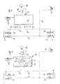
- the data transmission line S 9 serves for function monitoring of the emergency steering 15, as will be explained in detail below with reference to the representations according to FIGS. 4 to 7.
- FIGS. 4 and 6 or 5 and 7 correspond except for the differences described below based on 1 to 3 described embodiment.
- Significant difference in the embodiments according to FIGS. 4, 6 and 5, 7 it is that by means of these embodiments the previously with reference to FIGS. 1 to 3 Emergency steering function described in detail can be monitored. Thereby it is ensured that the electronic control unit S. Failure of the emergency steering function during normal driving of the Tracked vehicle can be recognized immediately. Because in normal operation the tracked vehicle is electronically steered so that a driver of the Tracked vehicle a possible failure of the hydraulic emergency steering can't notice. To ensure the functional fallback level for the The following is a breakdown of the electronic control described embodiments provided. Advantageously it is sufficient to carry out a corresponding functional check by the electronic control before each restart of the tracked vehicle perform.
- a detailed version of the emergency steering function is disclosed, which, apart from the monitoring means (described in more detail below), has a structure for the emergency steering function of the embodiment according to FIGS 1 to 3 can be used.
- the feed pump 18 is followed by two units.
- a steering unit 23 which is mechanically connected to the steering wheel 8 and, on the other hand, a release unit 25, which is a forced actuator that is automatically transferred to the functional position in the event of failure of the electronics.
- the steering unit 23 has two pressure reducers 23a and 23b, which are assigned to the right and left-hand hydraulic circuit H 1 for controlling the brake pistons 7b of the multi-disc brakes 6 on both sides of the vehicle.
- a 5/2-way valve is provided as a release unit or positive actuator 25, which valve is shown in its de-energized state in the illustration according to FIGS. 6 and 7. In the energized state, the lines, ie the hydraulic circuit H 1, are blocked. In this energized state, the line from the feed pump 18 takes place directly to the corresponding hydraulic motors 4.
- Each line H 1 is also assigned a 3/2-way valve which can be actuated together and either release the line to the brake pistons 7b or the return flow define these lines.
- two pressure sensors 22 are integrated in the lines H 1 near the multi-disc brakes 6, which can detect the line pressure in the two lines H 1 .
- an actuation switch is also in the Area of the handbrake 10 provided to the released or actuated To be able to detect the state of the handbrake 10.
- the pressure regulators or pressure reducers 23a, 23b reduce in the exemplary embodiment 4, 6 and also in the embodiment 5, 7 the feed pressure to about 14bar.
- the pressure increases right and falls left.
- the sinks Pressure to the right and rises to the left. This can be detected by the pressure sensors 22 become. If 14bar is not reached, one of the two is Pressure regulator 23a, 23b defective. This is particularly the case with one Spring breakage in one of the two pressure regulators 23a, 23b Obar.
- the handbrake When the 5/2-way valve 25 is energized, the handbrake is activated appropriate pressure adjusted. With the operating switch (previously described) the respective position of the handbrake can be detected. at open handbrake at a pump speed of preferably Higher than 900 revolutions per minute must have a feed pressure of 16 bar queue. The switching function is also used if a pressure sensor is defective of the positive actuator 25, i.e. of the 5/2-way valve, and the Pressure regulator 23a, 23b can still be monitored.
- the two Pressure regulator 23a, 23b monitored via two pressure switches 24.
- the ventilators The operating position of the handbrake is Monitored pressure switch, not shown.
- the position of the positive actuator in the form of the 5/2-way valve 25 via a position switch 26 recorded.
- the position switch 26 transmits the de-energized or energized position of the 5/2-way valve 25 to the electronic Control unit.
- the pressure switch causes a drop in pressure at the respective Pressure regulator 23a, 23b can be detected, so that in particular one Failure of a pressure regulator 23a, 23b can be seen.
- All of the function monitoring means described are electronic Control unit S coupled to that extent after a restart Issue a start approval for checking the corresponding functions or can refuse.
Landscapes
- Engineering & Computer Science (AREA)
- Transportation (AREA)
- Mechanical Engineering (AREA)
- Combustion & Propulsion (AREA)
- Chemical & Material Sciences (AREA)
- Automation & Control Theory (AREA)
- Regulating Braking Force (AREA)
- Valves And Accessory Devices For Braking Systems (AREA)
- Paper (AREA)
- Braking Systems And Boosters (AREA)
- Moving Of Heads (AREA)
- Air Bags (AREA)
- Vehicle Body Suspensions (AREA)
- Current-Collector Devices For Electrically Propelled Vehicles (AREA)
- Power Steering Mechanism (AREA)
Applications Claiming Priority (2)
| Application Number | Priority Date | Filing Date | Title |
|---|---|---|---|
| DE10154650 | 2001-10-30 | ||
| DE10154650A DE10154650C1 (de) | 2001-10-30 | 2001-10-30 | Kettenfahrzeug |
Publications (2)
| Publication Number | Publication Date |
|---|---|
| EP1308377A1 true EP1308377A1 (fr) | 2003-05-07 |
| EP1308377B1 EP1308377B1 (fr) | 2004-11-10 |
Family
ID=7704895
Family Applications (1)
| Application Number | Title | Priority Date | Filing Date |
|---|---|---|---|
| EP02020940A Expired - Lifetime EP1308377B1 (fr) | 2001-10-30 | 2002-09-19 | Véhicule à chenilles |
Country Status (6)
| Country | Link |
|---|---|
| US (1) | US6782960B2 (fr) |
| EP (1) | EP1308377B1 (fr) |
| AT (1) | ATE281967T1 (fr) |
| CA (1) | CA2409894C (fr) |
| DE (2) | DE10154650C1 (fr) |
| NO (1) | NO20025191L (fr) |
Cited By (3)
| Publication number | Priority date | Publication date | Assignee | Title |
|---|---|---|---|---|
| WO2015018395A1 (fr) * | 2013-08-09 | 2015-02-12 | Krauss-Maffei Wegmann Gmbh & Co. Kg | Véhicule |
| US20230040044A1 (en) * | 2020-04-20 | 2023-02-09 | Thyssenkrupp Presta Ag | Degradation concept for a steer-by-wire steering system |
| EP4624287A1 (fr) * | 2024-03-28 | 2025-10-01 | Kässbohrer Geländefahrzeug AG | Dameuse avec un entraînement à chenille |
Families Citing this family (13)
| Publication number | Priority date | Publication date | Assignee | Title |
|---|---|---|---|---|
| US7574290B2 (en) * | 2004-11-30 | 2009-08-11 | Trimble Navigation Limited | Method and system for implementing automatic vehicle control with parameter-driven disengagement |
| US7690734B2 (en) * | 2006-01-17 | 2010-04-06 | Gm Global Technology Operations, Inc. | Brake steering method and apparatus |
| US8844665B2 (en) * | 2007-12-27 | 2014-09-30 | Swissauto Powersport Llc | Skid steered all terrain vehicle |
| FR2949750B1 (fr) * | 2009-09-04 | 2011-10-07 | Converteam Technology Ltd | Chaine de propulsion |
| DE102015000594A1 (de) * | 2015-01-16 | 2016-07-21 | Knorr-Bremse Systeme für Nutzfahrzeuge GmbH | Bremsanlage für ein Fahrzeug sowie Verfahren zum Betreiben einer Bremsanlage für ein Fahrzeug |
| US10099735B2 (en) | 2016-11-01 | 2018-10-16 | Cnh Industrial America Llc | System and method for monitoring track tension for a track assembly of a work vehicle |
| US10604200B2 (en) | 2016-12-14 | 2020-03-31 | Ontario Drive & Gear Limited | All-terrain vehicle |
| CA2967149C (fr) | 2016-12-21 | 2024-04-30 | Peter Derek Visscher | Transmission d'entrainement de vehicule et systeme de direction assistee electriquement |
| JP2018134949A (ja) * | 2017-02-21 | 2018-08-30 | アイシン精機株式会社 | 運転支援装置 |
| DE102017215386A1 (de) * | 2017-09-01 | 2019-03-07 | Knorr-Bremse Systeme für Nutzfahrzeuge GmbH | Fußbremsmodul mit Notlenkfunktion |
| US10647306B2 (en) * | 2018-04-23 | 2020-05-12 | Goodrich Corporation | Measurement of contact maintaining control valve current for a hydraulic actuator |
| US10946869B2 (en) * | 2018-11-02 | 2021-03-16 | Danfoss Power Solutions Inc. | Vehicle steering control systems and methods |
| CN116215487B (zh) * | 2023-05-08 | 2023-07-18 | 太原科技大学 | 在线智能监控制动力矩的极地全地形车 |
Citations (2)
| Publication number | Priority date | Publication date | Assignee | Title |
|---|---|---|---|---|
| US4754824A (en) * | 1986-01-24 | 1988-07-05 | Ab Hagglund & Soner | Method and apparatus for steering a vehicle |
| EP0937614A2 (fr) * | 1998-02-21 | 1999-08-25 | Robert Bosch Gmbh | Procédé et appareil pour commander un système de freinage |
Family Cites Families (2)
| Publication number | Priority date | Publication date | Assignee | Title |
|---|---|---|---|---|
| US3692119A (en) * | 1971-04-23 | 1972-09-19 | Jasper J Tucker | Winch carrying snow grooming vehicle supported by skids and powered by an anchored drawline |
| US3994352A (en) * | 1975-03-19 | 1976-11-30 | The United States Of America As Represented By The Secretary Of The Army | Tracked vehicle emergency brake system |
-
2001
- 2001-10-30 DE DE10154650A patent/DE10154650C1/de not_active Withdrawn - After Issue
-
2002
- 2002-09-19 AT AT02020940T patent/ATE281967T1/de active
- 2002-09-19 DE DE50201506T patent/DE50201506D1/de not_active Expired - Lifetime
- 2002-09-19 EP EP02020940A patent/EP1308377B1/fr not_active Expired - Lifetime
- 2002-10-25 US US10/281,922 patent/US6782960B2/en not_active Expired - Fee Related
- 2002-10-28 CA CA2409894A patent/CA2409894C/fr not_active Expired - Fee Related
- 2002-10-29 NO NO20025191A patent/NO20025191L/no not_active Application Discontinuation
Patent Citations (2)
| Publication number | Priority date | Publication date | Assignee | Title |
|---|---|---|---|---|
| US4754824A (en) * | 1986-01-24 | 1988-07-05 | Ab Hagglund & Soner | Method and apparatus for steering a vehicle |
| EP0937614A2 (fr) * | 1998-02-21 | 1999-08-25 | Robert Bosch Gmbh | Procédé et appareil pour commander un système de freinage |
Cited By (4)
| Publication number | Priority date | Publication date | Assignee | Title |
|---|---|---|---|---|
| WO2015018395A1 (fr) * | 2013-08-09 | 2015-02-12 | Krauss-Maffei Wegmann Gmbh & Co. Kg | Véhicule |
| US20230040044A1 (en) * | 2020-04-20 | 2023-02-09 | Thyssenkrupp Presta Ag | Degradation concept for a steer-by-wire steering system |
| US12116051B2 (en) * | 2020-04-20 | 2024-10-15 | Thyssenkrupp Presta Ag | Degradation concept for a steer-by-wire steering system |
| EP4624287A1 (fr) * | 2024-03-28 | 2025-10-01 | Kässbohrer Geländefahrzeug AG | Dameuse avec un entraînement à chenille |
Also Published As
| Publication number | Publication date |
|---|---|
| DE10154650C1 (de) | 2003-05-08 |
| NO20025191D0 (no) | 2002-10-29 |
| CA2409894C (fr) | 2010-10-26 |
| US20030089535A1 (en) | 2003-05-15 |
| NO20025191L (no) | 2003-05-02 |
| ATE281967T1 (de) | 2004-11-15 |
| US6782960B2 (en) | 2004-08-31 |
| EP1308377B1 (fr) | 2004-11-10 |
| CA2409894A1 (fr) | 2003-04-30 |
| DE50201506D1 (de) | 2004-12-16 |
Similar Documents
| Publication | Publication Date | Title |
|---|---|---|
| EP1308377B1 (fr) | Véhicule à chenilles | |
| EP0613432B1 (fr) | Dispositif d'entrainement et de freinage d'un vehicule automobile | |
| EP1743823B1 (fr) | Entraînement pour véhicule de travail | |
| EP2096010B1 (fr) | Système de freinage pour un chariot de manutention | |
| DE19530612C2 (de) | Steuerung einer automatischen Kupplung | |
| DE4229041A1 (de) | Fahrzeug-bremssteuersystem | |
| WO2015090557A1 (fr) | Véhicule automobile | |
| DE2500627A1 (de) | Zugmaschine mit gewichtsuebertragungseinrichtung zwischen der kupplung und den schienenraedern | |
| DE19516639A1 (de) | Kraftfahrzeug mit einer Betriebs- und einer Feststellbremsanlage | |
| DE10339245A1 (de) | Bremssteuersystem für ein Fahrzeug | |
| EP3730363B1 (fr) | Système hydraulique et véhicule | |
| EP1050444A2 (fr) | Dispositif pour contrôler les feux de freinage | |
| DE102008049739A1 (de) | Zentrale Druckversorgung für Nebenantriebe | |
| DE10154651C1 (de) | Kettenfahrzeug mit einem Antriebssystem | |
| DE4446123C2 (de) | Vorrichtung zur Einwirkung auf die an der Lenkung eines Kraftfahrzeuges wirksamen Störkräfte | |
| EP0345203B1 (fr) | Installation de freinage avec moyen de pression régulé électroniquement | |
| DE102020204924B4 (de) | Bremssystem für ein Anhängerfahrzeug und Anhängerfahrzeug mit einem solchen Bremssystem | |
| DE10197080T5 (de) | Baumaschine mit Traktionssteuerung | |
| DE19855405B4 (de) | Hydraulische Servolenkung für Kraftfahrzeuge | |
| DE102022103840A1 (de) | Antriebsvorrichtung für eine Fahrzeugachse eines zweispurigen Fahrzeugs | |
| EP2070786B1 (fr) | Dispositif pour un conducteur de train d'asservissement rapide amélioré de la système de d'asservissement de freinage | |
| EP1440211B1 (fr) | Engin de travail et procede pour faire fonctionner un engin de travail | |
| EP3461707B1 (fr) | Système de commande d'un dispositif de freinage à commande hydraulique | |
| DE4230534C2 (de) | Fahrzeugantrieb | |
| WO2019179668A1 (fr) | Procédé servant à réguler la puissance d'entraînement d'un moteur à pilotage électronique servant à entraîner un générateur de pression d'un frein actionné par une force extérieure à patinage régulable d'un véhicule automobile |
Legal Events
| Date | Code | Title | Description |
|---|---|---|---|
| PUAI | Public reference made under article 153(3) epc to a published international application that has entered the european phase |
Free format text: ORIGINAL CODE: 0009012 |
|
| AK | Designated contracting states |
Designated state(s): AT BE BG CH CY CZ DE DK EE ES FI FR GB GR IE IT LI LU MC NL PT SE SK TR |
|
| AX | Request for extension of the european patent |
Extension state: AL LT LV MK RO SI |
|
| 17P | Request for examination filed |
Effective date: 20030517 |
|
| 17Q | First examination report despatched |
Effective date: 20031009 |
|
| AKX | Designation fees paid |
Designated state(s): AT CH DE LI |
|
| GRAP | Despatch of communication of intention to grant a patent |
Free format text: ORIGINAL CODE: EPIDOSNIGR1 |
|
| GRAS | Grant fee paid |
Free format text: ORIGINAL CODE: EPIDOSNIGR3 |
|
| GRAA | (expected) grant |
Free format text: ORIGINAL CODE: 0009210 |
|
| AK | Designated contracting states |
Kind code of ref document: B1 Designated state(s): AT CH DE LI |
|
| REG | Reference to a national code |
Ref country code: CH Ref legal event code: EP Ref country code: CH Ref legal event code: NV Representative=s name: BOVARD AG PATENTANWAELTE |
|
| REG | Reference to a national code |
Ref country code: IE Ref legal event code: FG4D Free format text: GERMAN |
|
| REF | Corresponds to: |
Ref document number: 50201506 Country of ref document: DE Date of ref document: 20041216 Kind code of ref document: P |
|
| REG | Reference to a national code |
Ref country code: IE Ref legal event code: FD4D |
|
| PLBE | No opposition filed within time limit |
Free format text: ORIGINAL CODE: 0009261 |
|
| STAA | Information on the status of an ep patent application or granted ep patent |
Free format text: STATUS: NO OPPOSITION FILED WITHIN TIME LIMIT |
|
| 26N | No opposition filed |
Effective date: 20050811 |
|
| REG | Reference to a national code |
Ref country code: CH Ref legal event code: PFA Owner name: KAESSBOHRER GELAENDEFAHRZEUG AG Free format text: KAESSBOHRER GELAENDEFAHRZEUG AG#KAESSBOHRERSTRASSE 11#88471 LAUPHEIM (DE) -TRANSFER TO- KAESSBOHRER GELAENDEFAHRZEUG AG#KAESSBOHRERSTRASSE 11#88471 LAUPHEIM (DE) |
|
| PGFP | Annual fee paid to national office [announced via postgrant information from national office to epo] |
Ref country code: CH Payment date: 20140922 Year of fee payment: 13 |
|
| PGFP | Annual fee paid to national office [announced via postgrant information from national office to epo] |
Ref country code: AT Payment date: 20140922 Year of fee payment: 13 |
|
| PGFP | Annual fee paid to national office [announced via postgrant information from national office to epo] |
Ref country code: DE Payment date: 20141027 Year of fee payment: 13 |
|
| REG | Reference to a national code |
Ref country code: DE Ref legal event code: R119 Ref document number: 50201506 Country of ref document: DE |
|
| REG | Reference to a national code |
Ref country code: CH Ref legal event code: PL |
|
| REG | Reference to a national code |
Ref country code: AT Ref legal event code: MM01 Ref document number: 281967 Country of ref document: AT Kind code of ref document: T Effective date: 20150919 |
|
| PG25 | Lapsed in a contracting state [announced via postgrant information from national office to epo] |
Ref country code: CH Free format text: LAPSE BECAUSE OF NON-PAYMENT OF DUE FEES Effective date: 20150930 Ref country code: DE Free format text: LAPSE BECAUSE OF NON-PAYMENT OF DUE FEES Effective date: 20160401 Ref country code: LI Free format text: LAPSE BECAUSE OF NON-PAYMENT OF DUE FEES Effective date: 20150930 |
|
| PG25 | Lapsed in a contracting state [announced via postgrant information from national office to epo] |
Ref country code: AT Free format text: LAPSE BECAUSE OF NON-PAYMENT OF DUE FEES Effective date: 20150919 |