EP1308593A2 - Jonction de canal de câble entre un battant de porte et un cadre de porte - Google Patents
Jonction de canal de câble entre un battant de porte et un cadre de porte Download PDFInfo
- Publication number
- EP1308593A2 EP1308593A2 EP02019685A EP02019685A EP1308593A2 EP 1308593 A2 EP1308593 A2 EP 1308593A2 EP 02019685 A EP02019685 A EP 02019685A EP 02019685 A EP02019685 A EP 02019685A EP 1308593 A2 EP1308593 A2 EP 1308593A2
- Authority
- EP
- European Patent Office
- Prior art keywords
- cable
- cable duct
- duct transition
- door
- guide sleeve
- Prior art date
- Legal status (The legal status is an assumption and is not a legal conclusion. Google has not performed a legal analysis and makes no representation as to the accuracy of the status listed.)
- Withdrawn
Links
- 230000007704 transition Effects 0.000 claims description 120
- 230000002093 peripheral effect Effects 0.000 claims description 24
- 238000007789 sealing Methods 0.000 claims description 5
- 239000002184 metal Substances 0.000 description 8
- 230000006978 adaptation Effects 0.000 description 2
- 238000003801 milling Methods 0.000 description 2
- 230000003287 optical effect Effects 0.000 description 2
- 235000014676 Phragmites communis Nutrition 0.000 description 1
- 238000010586 diagram Methods 0.000 description 1
- 238000010616 electrical installation Methods 0.000 description 1
- 238000003780 insertion Methods 0.000 description 1
- 230000037431 insertion Effects 0.000 description 1
- 230000010354 integration Effects 0.000 description 1
- 239000000463 material Substances 0.000 description 1
- 230000035515 penetration Effects 0.000 description 1
- 238000009420 retrofitting Methods 0.000 description 1
- 239000000126 substance Substances 0.000 description 1
- 230000000007 visual effect Effects 0.000 description 1
- XLYOFNOQVPJJNP-UHFFFAOYSA-N water Substances O XLYOFNOQVPJJNP-UHFFFAOYSA-N 0.000 description 1
Images


Classifications
-
- E—FIXED CONSTRUCTIONS
- E05—LOCKS; KEYS; WINDOW OR DOOR FITTINGS; SAFES
- E05D—HINGES OR SUSPENSION DEVICES FOR DOORS, WINDOWS OR WINGS
- E05D11/00—Additional features or accessories of hinges
- E05D11/0081—Additional features or accessories of hinges for transmitting energy, e.g. electrical cable routing
-
- E—FIXED CONSTRUCTIONS
- E05—LOCKS; KEYS; WINDOW OR DOOR FITTINGS; SAFES
- E05Y—INDEXING SCHEME ASSOCIATED WITH SUBCLASSES E05D AND E05F, RELATING TO CONSTRUCTION ELEMENTS, ELECTRIC CONTROL, POWER SUPPLY, POWER SIGNAL OR TRANSMISSION, USER INTERFACES, MOUNTING OR COUPLING, DETAILS, ACCESSORIES, AUXILIARY OPERATIONS NOT OTHERWISE PROVIDED FOR, APPLICATION THEREOF
- E05Y2900/00—Application of doors, windows, wings or fittings thereof
- E05Y2900/10—Application of doors, windows, wings or fittings thereof for buildings or parts thereof
- E05Y2900/13—Type of wing
- E05Y2900/132—Doors
Definitions
- the invention relates to a cable duct transition between a door leaf and a door frame, with a first Cable duct transition part, which is fixed to the door frame is, and a second cable duct transition part, which is firmly on Door leaf arranged and in relation to the door frame fixed first Cable duct transition part is movable.
- Such a cable duct transition serves to remove a cable from the To transfer the door leaf to the door frame, which on the one hand Door-side electrical devices, for example an electrical block lock, bolt switch or reed contacts, Escape door opener etc. connected and on the other hand with a frame-side power source is connected.
- Door-side electrical devices for example an electrical block lock, bolt switch or reed contacts, Escape door opener etc. connected and on the other hand with a frame-side power source is connected.
- the invention has for its object a cable duct transition between a door leaf and a door frame create the both closed and open Door can be made virtually invisible and its Assembly considerably simplified compared to the prior art is.
- the first cable duct transition part, which is fixed to the door frame, and the door leaf fixed second cable duct transition part in a door leaf Door hinge pivot bearing mounted on the door frame integrated and around a pivot axis of the hinge pivot bearing are rotatable to each other.
- the rotatable design of the doorframe-proof first cable duct transition part and of the door leaf-fixed second cable duct transition part Consequence that a mutual rotation of the two cable duct transition parts to the maximum swivel angle of the door leaf is limited in relation to the door frame.
- Cable duct transition has the door cable fixed first cable duct transition part one coaxial to the pivot axis of the door hinge pivot bearing arranged cable guide sleeve and the door wing fixed second cable duct transition part a coaxial to Pivot axis of the door hinge pivot bearing arranged cable guide sleeve on, with the two cable guide sleeves towards the pivot axis of the door hinge pivot bearing next to each other arranged and about the pivot axis of the hinge pivot bearing are rotatable to each other.
- the door frame fixed first cable duct transition part advantageous a cable entry socket, through which a cable from the door frame into the cable guide sleeve of the door frame fixed first cable duct transition part is feasible.
- the cable entry socket of the door frame is expedient first cable duct transition part perpendicular to the swivel axis the hinge pivot bearing arranged.
- the door wing fixed second cable duct transition part a cable entry socket has through which a cable from the door leaf in the cable guide sleeve of the door leaf-fixed second cable duct transition part is feasible. With this configuration is achievable that the electrical cable or one as such visible sheathing of the cable between the door frame and door leaf remains invisible.
- the cable entry socket of the door cable-fixed second cable duct transition part is expediently perpendicular to Pivot axis of the hinge pivot bearing arranged.
- one of the two cable guide sleeves on the other adjacent end section an inner radial step and the other of the two cable guide sleeves on their one adjacent End portion has an outer radial step, wherein the cable guide sleeve provided with the outer radial step with its end section in the one with the inner radial step provided cable guide sleeve is inserted.
- the cable guide sleeve provided with the outer radial step with its end section in the one with the inner radial step provided cable guide sleeve is inserted.
- a first O-sealing ring is arranged between the inner peripheral surface of the with the inner Radial stage formed end portion of a cable guide sleeve and the outer peripheral surface of the with the outer Radial stage formed end portion of the other cable guide sleeve.
- Cable duct transition is at the upper end of the door hinge pivot bearing arranged.
- Easy retrofitting already existing hinge pivot bearings with the invention Cable duct transition can be reached if the Transition between the hinge pivot bearing and the cable duct transition is formed by a pin head, the Pin section in a recess of the pivot axis of the Inserted hinge pivot bearing forming pivot is and for that about the hinge pivot bearing in upward
- the cable guide sleeve in the direction of the projecting head section of the lower cable duct transition part is rotatably arranged is.
- a second O-sealing ring is arranged.
- a material, color and shape adjustment of the Cable duct transition according to the invention to the existing hinge pivot mounting is with a comparatively low Effort attainable if on the outer peripheral surface of the upper one Cable guide sleeve sits an upper cover sleeve that itself over the lower cable guide sleeve to the cable entry socket of the lower cable duct transition part and one the cable entry socket of the upper cable duct transition part has assigned longitudinal slot.
- Such a cover sleeve can be optically large with little effort Design adaptation to the existing hinge pivot bearing, whereby they are assigned due to the upper cable entry connector Longitudinal slot in a simple manner via the upper cable guide sleeve can be pushed until it is with its lower edge against the lower cable entry connector of the cable duct transition encounters.
- a lower cover sleeve be provided, extending to the bottom of the top Cover sleeve or to the top of the cable entry socket of the extends lower cable duct transition part and one of the cable entry pipe assigned to the lower cable duct transition part Has longitudinal slot.
- Cable duct transition align the outer peripheral surfaces the upper cover sleeve and the lower cover sleeve with each other and with the outer peripheral surfaces of hinge sleeves the hinge pivot bearing.
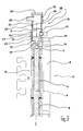
- Cable duct transition 1 forms in the shown Embodiment a technical-constructive unit with a door hinge pivot bearing 2, by means of which in the Figures 1 to 3 door wing, not shown, on one in the figures 1 to 3 door frame, also not shown, by one in Figure 3 by a dash-dotted line pivot axis 3 is pivotally mounted.
- the pivot axis 3 belongs to the hinge pivot bearing forming pivot pin 4, around which a hinge sleeve 5 a door hinge 6 on the door frame and an upper one Hinge sleeve 7 and a lower hinge sleeve 8 one Door hinge-side hinge 9 coaxial and rotatable to each other are stored.
- this is at the upper end of the door hinge pivot bearing 2 provided and it has an upper, door cable-resistant first cable duct transition part 10 and a lower, second cable duct transition part 11 that is fixed to the door wing on.
- pivot pin head 12 Between the lower, door leaf-fixed second cable duct transition part 11 and the upper end of the pivot axis 3 of the Door hinge pivot bearing 2 forming pivot pin 4 is in the shown a pin head 12, the one with a pin section 13 in one in the upper end section of the pivot pin 4 centrally formed recess 14 sits.
- a head portion 15 of the pin head 12 sits on the top End face of the pivot pin 4 and protrudes in the axial direction via the upper hinge sleeve 7 of the door hinge-side hinge 9 before.
- the lower, door leaf-fixed second cable duct transition part 11 has a cable guide sleeve 16 which is coaxial to the pivot pin 4 of the hinge pivot bearing 2 is arranged and with it lower face against the upper face of the upper Hinge sleeve 7 of the door leaf-side hinge 9 abuts and with its lower end portion, the inside diameter of which Corresponds to the outer diameter of the head section 15 of the pin head 12, arranged around the head portion 15 of the pin head 12 is.
- the lower cable guide sleeve 16 has a radial or perpendicular to the pivot axis 3 of the hinge pivot bearing 2 arranged cable entry socket 17, through the one Cable, which electrical equipment in the area of the door leaf, not shown, is assigned to the figures, from the door wing into the cable guide sleeve 16 of the lower door wing fixed second cable duct transition part 11 in or is transferable.
- the lower cable guide sleeve 16 has in the area of its upper one End portion formed on its inner peripheral surface inner radial stage 18.
- the upper cable guide sleeve 19 is in the area of its lower End portion on its outer peripheral surface with an outer Radial stage 21 formed.
- the dimensions of the inner radial step 18 of the lower cable guide sleeve 16 and the outer radial stage 21 of the upper Cable guide sleeve 19 are chosen so that the lower end portion the upper cable guide sleeve 19 with its outer peripheral surface against the inner peripheral surface of the upper end portion the lower cable guide sleeve 16 abuts.
- the upper Cable guide sleeve 19 and the lower cable guide sleeve 16 are to each other about the pivot axis 3 of the hinge pivot bearing 2 rotatable.
- the cable that is in the Cable duct transition 1 between door leaf and door frame the cable entry socket 17 of the lower door wing fixed second cable duct transition part 11, through the lower cable guide sleeve 16 of the same, the upper cable guide sleeve 19 of the upper part of the cable duct that is fixed to the door frame 10 and its cable inlet connector 20 is guided at Opening the door wing of a torsion or twist load subjected, resulting from the opening angle of the door leaf in relation to the door frame and accordingly the maximum possible opening angle of the door leaf in relation is limited to the door frame.
- the one formed by the cable duct transition part 1, the overpass of the cable, not shown in the figures, between Door frame and door wing cavity is against that Penetration of foreign bodies, moisture etc. protected, and through a first O-sealing ring 22, which between the Inner peripheral surface of the upper end portion of the lower cable guide sleeve 16 and the outer peripheral surface of the end portion the lower cable guide sleeve 19 is arranged, a second O-seal ring 23 which is between the outer peripheral surface the head portion 15 of the pin head 12 and the Inner peripheral surface of the lower end portion of the lower cable guide sleeve 16 is arranged, and by a cover cap 24 through which the upper end of the upper cable guide sleeve 19 is closed.
- an upper cover sleeve 25 is provided from the cap 24 or the upper end of the upper Cable guide sleeve 19 of the upper, door frame-fixed first cable duct transition part 10 over the upper cable guide sleeve 19 and the lower cable guide sleeve 16 to the upper end of the cable entry socket 17 of the lower door wing fixed second cable duct transition part 11 extends.
- the top cover sleeve 25 is formed with a longitudinal slot 26, the the cable entry socket 20 of the upper, door frame fixed first Cable duct transition part 10 is assigned.
- This lower one Cover sleeve 27 extends from the area of the upper End of the cable entry socket 17 of the lower, door leaf-fixed second cable duct transition part 11 to the lower end the lower cable guide sleeve 16 of the lower, door leaf fixed second cable duct transition part 11.
- This lower cover sleeve 27 has a longitudinal slot 28 which connects the cable entry 17 of the lower, door wing-fixed second cable duct transition part 11 is assigned.
- the upper cover sleeve 25 and the lower cover sleeve 27 of the cable duct transition 1 is an embodiment of the same reached, in whose outer peripheral surface with the outer peripheral surface the hinge sleeves 5, 7, 8 of the door hinge pivot bearing 2 is aligned.
- the above Cable duct transition 1 is an invisible transition of a Cable between a door frame and a door leaf possible. Due to the adapted design of the cable duct transition 1 to the hinge pivot mounting 2 is achieved that no evidence whatsoever of the existence of any between the Door frame and the cable running through the door leaf are visible.
Landscapes
- Engineering & Computer Science (AREA)
- Mechanical Engineering (AREA)
- Electric Cable Arrangement Between Relatively Moving Parts (AREA)
Applications Claiming Priority (2)
| Application Number | Priority Date | Filing Date | Title |
|---|---|---|---|
| DE2001153709 DE10153709B4 (de) | 2001-10-31 | 2001-10-31 | Kabelkanalübergang zwischen einem Türflügel und einer Türzarge |
| DE10153709 | 2001-10-31 |
Publications (2)
| Publication Number | Publication Date |
|---|---|
| EP1308593A2 true EP1308593A2 (fr) | 2003-05-07 |
| EP1308593A3 EP1308593A3 (fr) | 2005-08-17 |
Family
ID=7704316
Family Applications (1)
| Application Number | Title | Priority Date | Filing Date |
|---|---|---|---|
| EP02019685A Withdrawn EP1308593A3 (fr) | 2001-10-31 | 2002-09-04 | Jonction de canal de câble entre un battant de porte et un cadre de porte |
Country Status (2)
| Country | Link |
|---|---|
| EP (1) | EP1308593A3 (fr) |
| DE (1) | DE10153709B4 (fr) |
Cited By (4)
| Publication number | Priority date | Publication date | Assignee | Title |
|---|---|---|---|---|
| DE202006016439U1 (de) * | 2006-10-26 | 2008-03-06 | Dr. Hahn Gmbh & Co. Kg | Vorrichtung zur Verbindung von Leitungen |
| DE202010008551U1 (de) | 2010-09-16 | 2011-12-20 | Dr. Hahn Gmbh & Co. Kg | Anordnung zur Kabelführung |
| CN108075416A (zh) * | 2017-12-19 | 2018-05-25 | 上海电信工程有限公司 | 变电站旋转柜的线缆理线结构及理线方法 |
| CN110387720A (zh) * | 2018-04-23 | 2019-10-29 | 青岛海尔滚筒洗衣机有限公司 | 一种连接机构及衣物处理设备 |
Families Citing this family (1)
| Publication number | Priority date | Publication date | Assignee | Title |
|---|---|---|---|---|
| DE102005049487B4 (de) * | 2005-03-02 | 2010-05-20 | Huga Hubert Gaisendrees Gmbh & Co. Kg | Holztür mit Leuchtelement |
Family Cites Families (5)
| Publication number | Priority date | Publication date | Assignee | Title |
|---|---|---|---|---|
| GB1182185A (en) * | 1967-05-23 | 1970-02-25 | F & C Gould Ltd | Improvements in and relating to Hinges. |
| DE9200361U1 (de) * | 1992-01-15 | 1992-03-05 | Schlaffner, Sabine, 8000 München | Scharnier zur Überbrückung elektrischer Zuleitungen an Möbeln u.dgl. |
| DE9309749U1 (de) * | 1993-06-30 | 1993-08-26 | Shen, Jack, Taipeh/T'ai-pei | Drehgelenk für elektrische Geräte |
| DE29601862U1 (de) * | 1996-02-05 | 1996-05-02 | Peters Design GmbH, 31737 Rinteln | Metall-Drehgelenk mit Kabeldurchlaß |
| DE19744423A1 (de) * | 1996-10-09 | 1998-04-16 | Hermann Loewe | Klimaeinrichtung, Fenster und/oder Türe einer Klimaeinrichtung |
-
2001
- 2001-10-31 DE DE2001153709 patent/DE10153709B4/de not_active Expired - Fee Related
-
2002
- 2002-09-04 EP EP02019685A patent/EP1308593A3/fr not_active Withdrawn
Cited By (6)
| Publication number | Priority date | Publication date | Assignee | Title |
|---|---|---|---|---|
| DE202006016439U1 (de) * | 2006-10-26 | 2008-03-06 | Dr. Hahn Gmbh & Co. Kg | Vorrichtung zur Verbindung von Leitungen |
| DE202010008551U1 (de) | 2010-09-16 | 2011-12-20 | Dr. Hahn Gmbh & Co. Kg | Anordnung zur Kabelführung |
| WO2012034970A1 (fr) | 2010-09-16 | 2012-03-22 | Dr. Hahn Gmbh & Co. Kg | Système de cheminement de câble |
| CN108075416A (zh) * | 2017-12-19 | 2018-05-25 | 上海电信工程有限公司 | 变电站旋转柜的线缆理线结构及理线方法 |
| CN108075416B (zh) * | 2017-12-19 | 2024-02-23 | 上海电信工程有限公司 | 变电站旋转柜的线缆理线结构及理线方法 |
| CN110387720A (zh) * | 2018-04-23 | 2019-10-29 | 青岛海尔滚筒洗衣机有限公司 | 一种连接机构及衣物处理设备 |
Also Published As
| Publication number | Publication date |
|---|---|
| DE10153709A1 (de) | 2003-05-22 |
| EP1308593A3 (fr) | 2005-08-17 |
| DE10153709B4 (de) | 2004-08-12 |
Similar Documents
| Publication | Publication Date | Title |
|---|---|---|
| DE3316834C3 (de) | Betätigungsdorn zur Lagerung in einem Verschlußgehäuse für einen Türverschluß für einen Schaltschrank | |
| DE69702628T2 (de) | Ein Scharnier für metallische Türen und Fenster | |
| EP2649258A1 (fr) | Dispositif de guidage de câbles | |
| EP1947279B2 (fr) | Couvercle terminal pour un boîtier d'un mécanisme de commande et dispositif d'agencement du boîtier sur un vantail | |
| DE10153709B4 (de) | Kabelkanalübergang zwischen einem Türflügel und einer Türzarge | |
| CH715484A2 (de) | Scharnier mit einer Kabeldurchführung sowie ein Verfahren zum Montieren bzw. Demontieren des Scharniers. | |
| EP1489255B1 (fr) | Charnière pour arrangement caché entre battant et cadre de porte avec canal de câble | |
| EP3333345B1 (fr) | Charnière et système de porte | |
| EP4308780B1 (fr) | Charnière destinée à une porte ou une fenêtre | |
| DE102019128325B3 (de) | Scharnier | |
| DE10353944A1 (de) | Dämpfungseinrichtung für WC-Sitze oder WC-Deckel | |
| DE69716394T2 (de) | Elektrischer Verbinder mit Scharnier | |
| DE102005012704B4 (de) | Wassermischarmatur | |
| DE20114126U1 (de) | Band | |
| DE10329519B4 (de) | Türbeschlag mit Absturzsicherung | |
| EP3406839A1 (fr) | Unité d'obturation à changement de moteur simplifié | |
| DE202018001299U1 (de) | Verschließbares Bauelement wie Tür oder Fenster | |
| DE9002696U1 (de) | Scharnier | |
| EP1757762B2 (fr) | Articulation à charnière, pour fenêtres, portes ou similaires | |
| DE202009001856U1 (de) | Schlossgarnitur für Türen, Fenster o.dgl. | |
| DE29603589U1 (de) | Türband | |
| DE19728990C2 (de) | Kabelhalterung zum Befestigen und Herausführen von Kabeln | |
| EP1134344A2 (fr) | Tourillon pour portes, fenêtres, volets ou similaires | |
| DE10201563B4 (de) | Handgriff für ein Sanitärventil | |
| DE20000904U1 (de) | Scharnier |
Legal Events
| Date | Code | Title | Description |
|---|---|---|---|
| PUAI | Public reference made under article 153(3) epc to a published international application that has entered the european phase |
Free format text: ORIGINAL CODE: 0009012 |
|
| AK | Designated contracting states |
Designated state(s): AT BE BG CH CY CZ DE DK EE ES FI FR GB GR IE IT LI LU MC NL PT SE SK TR |
|
| AX | Request for extension of the european patent |
Extension state: AL LT LV MK RO SI |
|
| PUAL | Search report despatched |
Free format text: ORIGINAL CODE: 0009013 |
|
| AK | Designated contracting states |
Kind code of ref document: A3 Designated state(s): AT BE BG CH CY CZ DE DK EE ES FI FR GB GR IE IT LI LU MC NL PT SE SK TR |
|
| AX | Request for extension of the european patent |
Extension state: AL LT LV MK RO SI |
|
| AKX | Designation fees paid | ||
| STAA | Information on the status of an ep patent application or granted ep patent |
Free format text: STATUS: THE APPLICATION IS DEEMED TO BE WITHDRAWN |
|
| 18D | Application deemed to be withdrawn |
Effective date: 20060221 |
|
| REG | Reference to a national code |
Ref country code: DE Ref legal event code: 8566 |