EP1308675B1 - Appareil de chauffage au gaz - Google Patents
Appareil de chauffage au gaz Download PDFInfo
- Publication number
- EP1308675B1 EP1308675B1 EP02257652A EP02257652A EP1308675B1 EP 1308675 B1 EP1308675 B1 EP 1308675B1 EP 02257652 A EP02257652 A EP 02257652A EP 02257652 A EP02257652 A EP 02257652A EP 1308675 B1 EP1308675 B1 EP 1308675B1
- Authority
- EP
- European Patent Office
- Prior art keywords
- combustion
- burner
- porous body
- air
- upper panel
- Prior art date
- Legal status (The legal status is an assumption and is not a legal conclusion. Google has not performed a legal analysis and makes no representation as to the accuracy of the status listed.)
- Expired - Lifetime
Links
Images


Classifications
-
- F—MECHANICAL ENGINEERING; LIGHTING; HEATING; WEAPONS; BLASTING
- F23—COMBUSTION APPARATUS; COMBUSTION PROCESSES
- F23D—BURNERS
- F23D14/00—Burners for combustion of a gas, e.g. of a gas stored under pressure as a liquid
- F23D14/46—Details
- F23D14/60—Devices for simultaneous control of gas and combustion air
-
- F—MECHANICAL ENGINEERING; LIGHTING; HEATING; WEAPONS; BLASTING
- F23—COMBUSTION APPARATUS; COMBUSTION PROCESSES
- F23D—BURNERS
- F23D14/00—Burners for combustion of a gas, e.g. of a gas stored under pressure as a liquid
- F23D14/12—Radiant burners
- F23D14/14—Radiant burners using screens or perforated plates
-
- F—MECHANICAL ENGINEERING; LIGHTING; HEATING; WEAPONS; BLASTING
- F23—COMBUSTION APPARATUS; COMBUSTION PROCESSES
- F23D—BURNERS
- F23D14/00—Burners for combustion of a gas, e.g. of a gas stored under pressure as a liquid
- F23D14/12—Radiant burners
- F23D14/16—Radiant burners using permeable blocks
-
- F—MECHANICAL ENGINEERING; LIGHTING; HEATING; WEAPONS; BLASTING
- F24—HEATING; RANGES; VENTILATING
- F24C—DOMESTIC STOVES OR RANGES ; DETAILS OF DOMESTIC STOVES OR RANGES, OF GENERAL APPLICATION
- F24C3/00—Stoves or ranges for gaseous fuels
- F24C3/04—Stoves or ranges for gaseous fuels with heat produced wholly or partly by a radiant body, e.g. by a perforated plate
- F24C3/06—Stoves or ranges for gaseous fuels with heat produced wholly or partly by a radiant body, e.g. by a perforated plate without any visible flame
- F24C3/067—Ranges
-
- F—MECHANICAL ENGINEERING; LIGHTING; HEATING; WEAPONS; BLASTING
- F24—HEATING; RANGES; VENTILATING
- F24C—DOMESTIC STOVES OR RANGES ; DETAILS OF DOMESTIC STOVES OR RANGES, OF GENERAL APPLICATION
- F24C3/00—Stoves or ranges for gaseous fuels
- F24C3/12—Arrangement or mounting of control or safety devices
- F24C3/126—Arrangement or mounting of control or safety devices on ranges
-
- Y—GENERAL TAGGING OF NEW TECHNOLOGICAL DEVELOPMENTS; GENERAL TAGGING OF CROSS-SECTIONAL TECHNOLOGIES SPANNING OVER SEVERAL SECTIONS OF THE IPC; TECHNICAL SUBJECTS COVERED BY FORMER USPC CROSS-REFERENCE ART COLLECTIONS [XRACs] AND DIGESTS
- Y02—TECHNOLOGIES OR APPLICATIONS FOR MITIGATION OR ADAPTATION AGAINST CLIMATE CHANGE
- Y02B—CLIMATE CHANGE MITIGATION TECHNOLOGIES RELATED TO BUILDINGS, e.g. HOUSING, HOUSE APPLIANCES OR RELATED END-USER APPLICATIONS
- Y02B40/00—Technologies aiming at improving the efficiency of home appliances, e.g. induction cooking or efficient technologies for refrigerators, freezers or dish washers
-
- Y—GENERAL TAGGING OF NEW TECHNOLOGICAL DEVELOPMENTS; GENERAL TAGGING OF CROSS-SECTIONAL TECHNOLOGIES SPANNING OVER SEVERAL SECTIONS OF THE IPC; TECHNICAL SUBJECTS COVERED BY FORMER USPC CROSS-REFERENCE ART COLLECTIONS [XRACs] AND DIGESTS
- Y02—TECHNOLOGIES OR APPLICATIONS FOR MITIGATION OR ADAPTATION AGAINST CLIMATE CHANGE
- Y02E—REDUCTION OF GREENHOUSE GAS [GHG] EMISSIONS, RELATED TO ENERGY GENERATION, TRANSMISSION OR DISTRIBUTION
- Y02E20/00—Combustion technologies with mitigation potential
- Y02E20/34—Indirect CO2mitigation, i.e. by acting on non CO2directly related matters of the process, e.g. pre-heating or heat recovery
Definitions
- the present invention relates to a gas heater for heating an object placed on an upper panel above a combustion chamber without exposing flames.
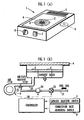
- FIG. 3(a) of the accompanying drawings shows a previously considered gas heater having a combustion chamber which houses a burner 100 therein and a heat-resistant upper panel 101 of glass disposed above the combustion chamber.
- the gas heater heats an object that is placed on the upper panel 101 without exposing flames.
- An air supply/discharge fan 102 supplies combustion air to the burner 100, and a combustion gas from the burner 100 is discharged from an exhaust slot 103.
- FIG. 3(b) of the accompanying drawings shows the previously considered gas heater in vertical cross section with some parts being illustrated in block form.
- a controller 130 controls a gas proportional valve 124 to control the flow rate of a fuel gas that is supplied from a gas supply passage 121 through a nozzle 122 to a mixture pipe 123, according to a target combustion rate which is set for the burner 100 by a combustion rate adjusting switch 104 that adjusts the combustion rate of the burner 100.
- the controller 130 also controls the air supply/discharge fan 102 to control the flow rate of combustion air supplied to the mixture pipe 123.
- the gas supply passage 121 has a main gas valve 125 at its end connected to the mixture pipe 123.
- a porous body 105 is disposed in a combustion gas exhaust passage defined in the burner 100. When the porous body 105 is heated by the heat of the combustion gas, the porous body 105 becomes red hot. When the burner 100 is in operation, it generates heat 111 from its surface due to combustion flames 110 that are produced by the combustion of the fuel gas, and the porous body 105 also generates radiant heat 112 as it becomes red hot. Therefore, the gas burner has a high thermal efficiency.
- EP 0601270-A1 discloses a combustion apparatus provided with a heat recirculating function whereby waste heat generated by a centrally disposed combustion surface can be used to pre-heat porous mats disposed around the combustion burner.
- EP 1225 393 - A1 discloses a combustion apparatus according to the preamble of claim 1, provided with a surface combustion burner disposed around the porous body.
- Preferred embodiments of the present invention seek to provide a gas heater which is capable of suppressing the radiation of heat energy into a space around an object which is heated by the gas heater, depending on the size of the object.
- An embodiment of the present invention is concerned with an improvement over a gas heater for heating an object placed on an upper panel disposed above a combustion chamber of the gas heater, comprising: an air-permeable porous body disposed in said combustion chamber; a combustion burner having a combustion surface disposed in confronting relation to said upper panel; fuel gas supply means for supplying a fuel gas to said combustion burner; an exhaust passage having an end communicating with said combustion chamber through said porous body and an opposite end communicating with an exhaust slot; an air supply/discharge fan for supplying combustion air to said combustion burner and delivering combustion exhaust gases from said combustion burner through said porous body and said exhaust passage to said exhaust slot; characterised by a red-hot area changing means for changing an air-fuel ratio, which represents the ratio of a flow rate of the combustion air supplied by said air supply/discharge fan to said combustion burner to a flow rate of the fuel gas supplied from said fuel gas supply means to said combustion burner, in order to change a red hot area for heating an object placed on said upper panel from an area corresponding to a region above
- the inventor of the present invention has found that the effective heating area or "red-hot area" on the upper panel is changed when the ratio between a flow rate of the fuel gas supplied to the burner and a flow rate of the combustion air supplied to the burner is changed at the time the fuel gas is combusted.
- the effective heating area changing means As the air-fuel ratio is increased by the effective heating area changing means, combustion flames produced by the burner are lifted off the combustion surface of the burner, and attracted to the porous burner. At this time, since the combustion surface of the burner does not become red hot, the heat radiated upwardly of the burner is reduced. However, because the combustion exhaust gases from the burner are drawn into the porous body and heat the porous body, the porous body emits radiant heat. Consequently, the effective heating area on the upper panel is reduced to an area over the porous body.
- the effective heating area changing means comprises means for reducing the effective heating area on the upper panel by setting the air-fuel ratio to a value greater than a predetermined air-fuel ratio which is determined to provide a good combustion efficiency of the burner.
- the porous body is heated by the combustion exhaust gases emitted from the burner and absorbed by the porous body to at least a temperature required to re-combust unburned gases contained in the combustion exhaust gases.
- the combustion state of the burner is made poor, and the burner emits combustion exhaust gases containing unburned gases due to incomplete combustion.
- the unburned gases are absorbed by the porous body which has been heated by the combustion exhaust gases from the burner, and are re-combusted by the porous body, which radiates heat.
- the thermal efficiency of the gas heater as a whole is prevented from being unduly lowered, and the unburned gases are prevented from being discharged from the exhaust slot.
- a gas heater 1 has an annular surface-combustion burner 2 and an air-permeable porous body 3 which are disposed in a combustion chamber and a heat-resistant upper panel 4 of glass disposed above the combustion chamber.
- the gas heater 1 heats an object that is placed on the upper panel 4 without exposing flames.
- the gas heater 1 also has an air supply/ discharge fan 6 for supplying combustion air to the burner 2 and delivering combustion exhaust gases from the burner 2 through the porous body 3 and an exhaust passage (not shown) into an exhaust slot 5, a capacity selector switch 7 for changing effective heating areas of the upper panel 4, and a combustion rate adjusting switch 8 for adjusting the combustion rate of the burner 2.
- FIG. 1(b) shows vertical cross section specific structural details of the gas heater illustrated in FIG. 1(a) .
- the burner 2 is supplied with combustion air from an air supply passage 20 by the air supply/discharge fan 6.
- a fuel gas supplied from a gas supply pipe 21 is injected into the air supply passage 20 from a nozzle 22 mounted on the end of the gas supply pipe 21 which is connected to the air supply passage 20.
- the gas supply pipe 21 and the nozzle 22 make up a fuel gas supply means according to the present invention.
- the gas supply pipe 21 has a main gas valve 23 and a gas proportional valve 24 which are successively disposed in the order named from its upstream end.
- the gas heater 1 is controlled in operation by a controller 30 whose functions include a function as an effective heating area changing means according to the present invention.
- the capacity selector switch 7 and the combustion rate adjusting switch 8 are connected to the controller 30.
- the controller 30 controls a combustion process carried out by the burner 2 depending on user's actions on the capacity selector switch 7 and the combustion rate adjusting switch 8.
- the controller 30 sets an air-fuel ratio, i.e., the ratio of the flow rate of the combustion air supplied by the air supply/discharge fan 6 to the burner 2 to the flow rate of the fuel gas supplied from the nozzle 22 to the burner 22, to a predetermined air-fuel ratio (e.g., 1.3) determined for a good combustion efficiency of the burner 2.
- a predetermined air-fuel ratio e.g., 1.3
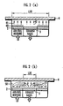
- the upper panel 4 provides an effective heating area which is substantially located within a circle having the diameter (L10 in FIG. 2(a) ) of the burner 2.
- the controller 30 sets the air-fuel ratio to a value (e.g., in a range from 1.7 to 2.0) that is larger than the predetermined air-fuel ratio (1.3).
- a value e.g., in a range from 1.7 to 2.0
- the combustion rate in the burner 2 is lowered.
- the combustion flames 50 produced by the burner 2 are lifted off, i.e., blown away from, the combustion surface of the burner 2, producing blue flames representing incomplete combustion.
- the combustion surface of the burner 2 Since the blue flames are spaced from the combustion surface of the burner 2, the combustion surface of the burner 2 is not heated. Therefore, the combustion surface of the burner 2 does not become red hot, and the upper panel 4 above the burner 2 does not become hot. High-temperature combustion exhaust gases produced from the lifted combustion flames 50 are absorbed by the porous body 3, which is heated by the high-temperature combustion exhaust gases and becomes red hot, discharging heat through the upper panel 4 above the porous body 3. Therefore, the upper panel 4 provides an effective heating area which is substantially located within a circle having the diameter (L20 in FIG. 2(b) ) of the porous body 3. The effective heating area provided by the upper panel 4 at this time is smaller than the effective heating area provided by the upper panel 4 when the capacity selector switch 7 is shifted to the "high capacity" position.
- the cooker who uses the gas heater can select one of the above effective heating areas depending on the size of a cooking utensil to be heated, e.g., a pan.
- a cooking utensil to be heated e.g., a pan.
- the user can select the smaller effective heating area, preventing substantial heat from being radiated from the gas heater into a space around the cooking utensil and hence preventing handles of the cooking utensil from being unduly heated.
- the combustion efficiency of the burner 2 is lowered, and the combustion exhaust gases emitted from the burner 2 contain a large amount of unburned gases due to the incomplete combustion.
- the unburned gases are absorbed by the porous body 3 which has been heated by the combustion exhaust gases from the burner 2 to a high temperature of, e.g., 900°C which corresponds to a temperature required to re-combust the unburned gases. Therefore, the porous body 3 completely combusts the unburned gases and radiates the heat generated by the complete combustion of the unburned gases.
- the thermal efficiency of the gas heater is prevented from being unduly lowered due to the air-rich air-fuel mixture supplied to the burner 2, and the unburned gases are prevented from being discharged from the exhaust slot 5.
- the air-fuel ratio may be changed in one of the following three alternative processes: (1) The flow rate of the combustion air supplied to the burner 2 is set to the same value as when the capacity selector switch 7 is shifted to the "high capacity” position, and the flow rate of the fuel gas supplied to the burner 2 is reduced. (2) The flow rate of the combustion air supplied to the burner 2 is set to a value smaller than the value which is set when the capacity selector switch 7 is shifted to the "high capacity” position, and the flow rate of the fuel gas supplied to the burner 2 is reduced. (3) The flow rate of the fuel gas supplied to the burner 2 is set to the same value as when the capacity selector switch 7 is shifted to the "high capacity” position, and the flow rate of the combustion air supplied to the burner 2 is increased.
- the gas heater can provide on the upper panel 4 two alternative effective heating areas which correspond respectively to the "high capacity” position and the "low capacity” position.
- the gas heater may provide on the upper panel 4 three or more alternative effective heating areas.
- the controller 30 may set successively larger air-fuel ratios than the predetermined air-fuel ratio to lift the combustion flames off the burner 2 by successively larger distances therefrom to provide successively smaller effective heating areas on the upper panel 4.
Landscapes
- Engineering & Computer Science (AREA)
- Chemical & Material Sciences (AREA)
- Combustion & Propulsion (AREA)
- Mechanical Engineering (AREA)
- General Engineering & Computer Science (AREA)
- Gas Burners (AREA)
- Regulation And Control Of Combustion (AREA)
Claims (2)
- Appareil de chauffage au gaz (1) pour chauffer un objet placé sur un panneau supérieur (4) disposé au-dessus d'une chambre de combustion de l'appareil de chauffage au gaz, comprenant :- un corps poreux perméable à l'air (3) disposé dans ladite chambre de combustion ;- un brûleur de combustion (2) ayant une surface de combustion disposée en relation de confrontation avec ledit panneau supérieur, pour lequel ledit brûleur de combustion de surface est disposé autour dudit corps poreux ;- des moyens d'alimentation en gaz combustible (21, 22) pour délivrer un gaz combustible audit brûleur de combustion ;- un passage d'évacuation ayant une extrémité communiquant avec ladite chambre de combustion par l'intermédiaire dudit corps poreux (3) et une extrémité opposée communiquant avec une fente d'évacuation (15) ;- une soufflerie d'alimentation en air / décharge (6) pour alimenter en air de combustion ledit brûleur de combustion (2) et délivrer des gaz d'évacuation de combustion provenant dudit brûleur de combustion, par l'intermédiaire dudit corps poreux (3) et dudit passage d'évacuation, à ladite fente d'évacuation (5) ; caractérisé par- des moyens de changement de zone chauffée au rouge (7) pour changer un rapport air / combustible, qui représente le rapport d'un débit de l'air de combustion, délivré par ladite soufflerie d'alimentation en air / décharge (6) audit brûleur de combustion (2), à un débit du gaz combustible délivré, en provenance desdits moyens d'alimentation en gaz combustible, audit brûleur de combustion, afin de changer une zone chauffée au rouge pour chauffer un objet placé sur ledit panneau supérieur, à partir d'une zone (L20) correspondant à une région au-dessus du corps poreux, en une zone (L10) correspondant à une région au-dessus du corps poreux et de la surface de combustion, en outre caractérisé en ce que lesdits moyens de changement de zone chauffée au rouge peuvent être mis en oeuvre pour accroître le rapport air / combustible, de sorte que des flammes de combustion produites par le brûleur de combustion sont soulevées pour quitter la surface de combustion et être attirées dans le corps poreux, de sorte que la zone chauffée au rouge corresponde à la zone (L20) au-dessus du corps poreux (3).
- Appareil de chauffage au gaz selon la revendication 1, dans lequel lesdits moyens d'ajustement de zone chauffée au rouge (7) comprennent des moyens pour réduire la zone chauffée au rouge (L10 ; L20) sur ledit panneau supérieur (4) en établissant ledit rapport air / combustible à une valeur supérieure à un rapport air / combustible prédéterminé qui est déterminé pour procurer un bon rendement de combustion audit brûleur de combustion (2), dans lequel ledit corps poreux (3) est chauffé par les gaz d'évacuation de combustion émis à partir dudit brûleur (2) et absorbés par ledit corps poreux à au moins une température requise pour rebrûler des gaz non-brûlés contenus dans lesdits gaz d'évacuation de combustion.
Applications Claiming Priority (2)
| Application Number | Priority Date | Filing Date | Title |
|---|---|---|---|
| JP2001339774A JP3684345B2 (ja) | 2001-11-05 | 2001-11-05 | ガスこんろ |
| JP2001339774 | 2001-11-05 |
Publications (2)
| Publication Number | Publication Date |
|---|---|
| EP1308675A1 EP1308675A1 (fr) | 2003-05-07 |
| EP1308675B1 true EP1308675B1 (fr) | 2008-12-31 |
Family
ID=19154072
Family Applications (1)
| Application Number | Title | Priority Date | Filing Date |
|---|---|---|---|
| EP02257652A Expired - Lifetime EP1308675B1 (fr) | 2001-11-05 | 2002-11-05 | Appareil de chauffage au gaz |
Country Status (6)
| Country | Link |
|---|---|
| EP (1) | EP1308675B1 (fr) |
| JP (1) | JP3684345B2 (fr) |
| KR (1) | KR100448602B1 (fr) |
| CN (1) | CN1249380C (fr) |
| DE (1) | DE60230576D1 (fr) |
| ES (1) | ES2316526T3 (fr) |
Families Citing this family (8)
| Publication number | Priority date | Publication date | Assignee | Title |
|---|---|---|---|---|
| JP4547557B2 (ja) * | 2003-12-08 | 2010-09-22 | パロマ工業株式会社 | こんろ |
| KR100681386B1 (ko) * | 2005-01-12 | 2007-02-09 | 주식회사 경동네트웍 | 공연비감지센서를 이용한 연소장치 |
| WO2010018037A1 (fr) * | 2008-07-18 | 2010-02-18 | Nv Bekaert Sa | Isolation améliorée pour brûleur radiant |
| IT1406865B1 (it) * | 2011-01-12 | 2014-03-14 | Worgas Bruciatori Srl | Bruciatore ad elevata stabilita' perimetrale |
| WO2012166697A1 (fr) * | 2011-06-01 | 2012-12-06 | Premark Feg L.L.C. | Procédé de transformation d'agencement de brûleur à gaz découvert en un agencement de brûleur radiant à infrarouge |
| BR112017014146B1 (pt) * | 2014-12-30 | 2021-12-21 | Instituto Tecnológico Metropolitano | Sistema de combustão em leito poroso e de combustão turbulenta |
| CN104864421A (zh) * | 2015-06-02 | 2015-08-26 | 天津大学 | 一种全封闭红外加热炒菜灶 |
| USD833208S1 (en) * | 2017-10-26 | 2018-11-13 | Etekcity Corporation | Electric warmer |
Family Cites Families (7)
| Publication number | Priority date | Publication date | Assignee | Title |
|---|---|---|---|---|
| FR2076174A5 (fr) * | 1970-01-05 | 1971-10-15 | Tappan Cy | |
| JPS6460102A (en) * | 1987-08-31 | 1989-03-07 | Mitsubishi Electric Corp | Antenna system |
| JP2578833B2 (ja) * | 1987-10-14 | 1997-02-05 | 大阪瓦斯株式会社 | 密閉型コンロ |
| JPH0166502U (fr) * | 1987-10-22 | 1989-04-27 | ||
| JP2682361B2 (ja) * | 1992-12-09 | 1997-11-26 | 日本鋼管株式会社 | 排熱回収型燃焼装置 |
| JP3715369B2 (ja) * | 1996-03-18 | 2005-11-09 | 東京瓦斯株式会社 | 炎漏出防止型コンロ |
| JP5989362B2 (ja) * | 2012-03-08 | 2016-09-07 | 第一電子工業株式会社 | コネクタ |
-
2001
- 2001-11-05 JP JP2001339774A patent/JP3684345B2/ja not_active Expired - Fee Related
-
2002
- 2002-07-23 KR KR10-2002-0043158A patent/KR100448602B1/ko not_active Expired - Fee Related
- 2002-11-04 CN CNB021499780A patent/CN1249380C/zh not_active Expired - Fee Related
- 2002-11-05 ES ES02257652T patent/ES2316526T3/es not_active Expired - Lifetime
- 2002-11-05 EP EP02257652A patent/EP1308675B1/fr not_active Expired - Lifetime
- 2002-11-05 DE DE60230576T patent/DE60230576D1/de not_active Expired - Lifetime
Also Published As
| Publication number | Publication date |
|---|---|
| EP1308675A1 (fr) | 2003-05-07 |
| JP3684345B2 (ja) | 2005-08-17 |
| JP2003139329A (ja) | 2003-05-14 |
| ES2316526T3 (es) | 2009-04-16 |
| KR20030038335A (ko) | 2003-05-16 |
| KR100448602B1 (ko) | 2004-09-13 |
| CN1417522A (zh) | 2003-05-14 |
| CN1249380C (zh) | 2006-04-05 |
| DE60230576D1 (de) | 2009-02-12 |
Similar Documents
| Publication | Publication Date | Title |
|---|---|---|
| US6425388B1 (en) | Pizza oven deck | |
| AU739705B2 (en) | Electric cooking oven with infrared gas broiler | |
| CN210227853U (zh) | 窑烤炉 | |
| JPS5912930B2 (ja) | ガスレンジ | |
| EP1308675B1 (fr) | Appareil de chauffage au gaz | |
| CA1302816C (fr) | Appareil de cuisson a gaz | |
| EP1467153B1 (fr) | Fourneau a gaz | |
| EP1316756B1 (fr) | Chauffage de gaz | |
| WO1995025928A2 (fr) | Bruleur fluidique | |
| EP1312867B1 (fr) | Elément chauffant de gas | |
| CN217978936U (zh) | 电气两用的组合灶具 | |
| JP3864853B2 (ja) | 調理器 | |
| US20020157659A1 (en) | Gas broiler | |
| JP2000193211A (ja) | コンロ用バ―ナ | |
| KR200363754Y1 (ko) | 복사열을 이용하는 가스 버너 | |
| JP3886461B2 (ja) | ガスコンロ | |
| CN218328130U (zh) | 一种能调节火焰的燃烧器及燃气炉灶 | |
| CN213155476U (zh) | 一种燃气烤炉 | |
| KR920003238Y1 (ko) | 장작형 난방기 | |
| KR20040025334A (ko) | 상업용 가스밥솥의 버너 | |
| KR20060032359A (ko) | 가스 복사 조리기기 | |
| JPH03210216A (ja) | ガス調理器 | |
| KR20050051244A (ko) | 가스복사버너 | |
| JPH0652124B2 (ja) | ガスバーナ | |
| KR20050051243A (ko) | 가스복사버너 |
Legal Events
| Date | Code | Title | Description |
|---|---|---|---|
| PUAI | Public reference made under article 153(3) epc to a published international application that has entered the european phase |
Free format text: ORIGINAL CODE: 0009012 |
|
| AK | Designated contracting states |
Designated state(s): AT BE BG CH CY CZ DE DK EE ES FI FR GB GR IE IT LI LU MC NL PT SE SK TR |
|
| AX | Request for extension of the european patent |
Extension state: AL LT LV MK RO SI |
|
| 17P | Request for examination filed |
Effective date: 20030731 |
|
| AKX | Designation fees paid |
Designated state(s): DE ES FR GB IT NL |
|
| GRAP | Despatch of communication of intention to grant a patent |
Free format text: ORIGINAL CODE: EPIDOSNIGR1 |
|
| GRAS | Grant fee paid |
Free format text: ORIGINAL CODE: EPIDOSNIGR3 |
|
| GRAA | (expected) grant |
Free format text: ORIGINAL CODE: 0009210 |
|
| AK | Designated contracting states |
Kind code of ref document: B1 Designated state(s): DE ES FR GB IT NL |
|
| REG | Reference to a national code |
Ref country code: GB Ref legal event code: FG4D |
|
| REF | Corresponds to: |
Ref document number: 60230576 Country of ref document: DE Date of ref document: 20090212 Kind code of ref document: P |
|
| RIN2 | Information on inventor provided after grant (corrected) |
Inventor name: YANO KOJI Inventor name: SOBUE TSUTOMU Inventor name: YAMADA, YUTAKA |
|
| REG | Reference to a national code |
Ref country code: ES Ref legal event code: FG2A Ref document number: 2316526 Country of ref document: ES Kind code of ref document: T3 |
|
| PLBE | No opposition filed within time limit |
Free format text: ORIGINAL CODE: 0009261 |
|
| STAA | Information on the status of an ep patent application or granted ep patent |
Free format text: STATUS: NO OPPOSITION FILED WITHIN TIME LIMIT |
|
| 26N | No opposition filed |
Effective date: 20091001 |
|
| PGFP | Annual fee paid to national office [announced via postgrant information from national office to epo] |
Ref country code: DE Payment date: 20121121 Year of fee payment: 11 Ref country code: FR Payment date: 20121130 Year of fee payment: 11 |
|
| PGFP | Annual fee paid to national office [announced via postgrant information from national office to epo] |
Ref country code: IT Payment date: 20121127 Year of fee payment: 11 Ref country code: GB Payment date: 20121120 Year of fee payment: 11 Ref country code: ES Payment date: 20121127 Year of fee payment: 11 |
|
| PGFP | Annual fee paid to national office [announced via postgrant information from national office to epo] |
Ref country code: NL Payment date: 20121120 Year of fee payment: 11 |
|
| REG | Reference to a national code |
Ref country code: NL Ref legal event code: V1 Effective date: 20140601 |
|
| GBPC | Gb: european patent ceased through non-payment of renewal fee |
Effective date: 20131105 |
|
| REG | Reference to a national code |
Ref country code: FR Ref legal event code: ST Effective date: 20140731 |
|
| REG | Reference to a national code |
Ref country code: DE Ref legal event code: R119 Ref document number: 60230576 Country of ref document: DE Effective date: 20140603 |
|
| PG25 | Lapsed in a contracting state [announced via postgrant information from national office to epo] |
Ref country code: DE Free format text: LAPSE BECAUSE OF NON-PAYMENT OF DUE FEES Effective date: 20140603 Ref country code: NL Free format text: LAPSE BECAUSE OF NON-PAYMENT OF DUE FEES Effective date: 20140601 Ref country code: IT Free format text: LAPSE BECAUSE OF NON-PAYMENT OF DUE FEES Effective date: 20131105 |
|
| PG25 | Lapsed in a contracting state [announced via postgrant information from national office to epo] |
Ref country code: GB Free format text: LAPSE BECAUSE OF NON-PAYMENT OF DUE FEES Effective date: 20131105 Ref country code: FR Free format text: LAPSE BECAUSE OF NON-PAYMENT OF DUE FEES Effective date: 20131202 |
|
| REG | Reference to a national code |
Ref country code: ES Ref legal event code: FD2A Effective date: 20150327 |
|
| PG25 | Lapsed in a contracting state [announced via postgrant information from national office to epo] |
Ref country code: ES Free format text: LAPSE BECAUSE OF NON-PAYMENT OF DUE FEES Effective date: 20131106 |