EP1308752A2 - Système de surveillance de l'extérieur d'un véhicule et méthode là-dessous - Google Patents
Système de surveillance de l'extérieur d'un véhicule et méthode là-dessous Download PDFInfo
- Publication number
- EP1308752A2 EP1308752A2 EP02024447A EP02024447A EP1308752A2 EP 1308752 A2 EP1308752 A2 EP 1308752A2 EP 02024447 A EP02024447 A EP 02024447A EP 02024447 A EP02024447 A EP 02024447A EP 1308752 A2 EP1308752 A2 EP 1308752A2
- Authority
- EP
- European Patent Office
- Prior art keywords
- distance data
- dimensional object
- distance
- laser
- image
- Prior art date
- Legal status (The legal status is an assumption and is not a legal conclusion. Google has not performed a legal analysis and makes no representation as to the accuracy of the status listed.)
- Withdrawn
Links
Images


Classifications
-
- G—PHYSICS
- G06—COMPUTING OR CALCULATING; COUNTING
- G06T—IMAGE DATA PROCESSING OR GENERATION, IN GENERAL
- G06T7/00—Image analysis
- G06T7/60—Analysis of geometric attributes
-
- G—PHYSICS
- G01—MEASURING; TESTING
- G01S—RADIO DIRECTION-FINDING; RADIO NAVIGATION; DETERMINING DISTANCE OR VELOCITY BY USE OF RADIO WAVES; LOCATING OR PRESENCE-DETECTING BY USE OF THE REFLECTION OR RERADIATION OF RADIO WAVES; ANALOGOUS ARRANGEMENTS USING OTHER WAVES
- G01S11/00—Systems for determining distance or velocity not using reflection or reradiation
- G01S11/12—Systems for determining distance or velocity not using reflection or reradiation using electromagnetic waves other than radio waves
-
- G—PHYSICS
- G01—MEASURING; TESTING
- G01S—RADIO DIRECTION-FINDING; RADIO NAVIGATION; DETERMINING DISTANCE OR VELOCITY BY USE OF RADIO WAVES; LOCATING OR PRESENCE-DETECTING BY USE OF THE REFLECTION OR RERADIATION OF RADIO WAVES; ANALOGOUS ARRANGEMENTS USING OTHER WAVES
- G01S17/00—Systems using the reflection or reradiation of electromagnetic waves other than radio waves, e.g. lidar systems
- G01S17/86—Combinations of lidar systems with systems other than lidar, radar or sonar, e.g. with direction finders
-
- G—PHYSICS
- G01—MEASURING; TESTING
- G01S—RADIO DIRECTION-FINDING; RADIO NAVIGATION; DETERMINING DISTANCE OR VELOCITY BY USE OF RADIO WAVES; LOCATING OR PRESENCE-DETECTING BY USE OF THE REFLECTION OR RERADIATION OF RADIO WAVES; ANALOGOUS ARRANGEMENTS USING OTHER WAVES
- G01S17/00—Systems using the reflection or reradiation of electromagnetic waves other than radio waves, e.g. lidar systems
- G01S17/88—Lidar systems specially adapted for specific applications
- G01S17/89—Lidar systems specially adapted for specific applications for mapping or imaging
-
- G—PHYSICS
- G01—MEASURING; TESTING
- G01S—RADIO DIRECTION-FINDING; RADIO NAVIGATION; DETERMINING DISTANCE OR VELOCITY BY USE OF RADIO WAVES; LOCATING OR PRESENCE-DETECTING BY USE OF THE REFLECTION OR RERADIATION OF RADIO WAVES; ANALOGOUS ARRANGEMENTS USING OTHER WAVES
- G01S17/00—Systems using the reflection or reradiation of electromagnetic waves other than radio waves, e.g. lidar systems
- G01S17/88—Lidar systems specially adapted for specific applications
- G01S17/93—Lidar systems specially adapted for specific applications for anti-collision purposes
- G01S17/931—Lidar systems specially adapted for specific applications for anti-collision purposes of land vehicles
Definitions
- the present invention relates to a monitor system of vehicle outside for detecting a distance between a vehicle and a three-dimensional object existing in front of the vehicle based on information from an image and an information derived from a laser radar, and to method of monitoring of vehicle outside.
- the advanced safety vehicle includes a TV camera, a laser radar, and like mounted thereon, detects preceding vehicles and obstructs, determines a degree of danger of collision therewith, and gives an alarm to a driver. And the vehicle is stopped by being automatically applied with a brake or automatically increases or decreases its running speed so as to keep a safe distance between the vehicle and a preceding vehicle.
- the measurement errors in the image and the laser radar are caused by the difference between the characteristics of the distance data obtained by the image and the characteristics of the distance data obtained by the laser radar.
- the laser radar mainly detects the reflectors of the vehicle.
- the distance of the vehicle detected by the image has a large measurement error, and the vehicle may be detected as if there is a three-dimensional object at a farther position.
- An object of the present invention which was made in view of circumstances described above, is to provide a monitor system of vehicle outside capable of promptly and accurately recognizing a three-dimensional object existing in front of the vehicle based on the information from an image and the information from a laser radar without executing unnecessary processing, and to provide a method of monitoring of a vehicle outside.
- the monitor system of vehicle outside includes image-measured distance detection means for detecting the distance data between the vehicle and a three-dimensional object existing in front of the vehicle based on the information of an image in front of the vehicle, laser-measured distance detection means for detecting the distance data between the vehicle and the three-dimensional object existing in front of the vehicle based on the information of a laser radar for projecting a laser beam from the vehicle. Further, the monitor system includes three-dimensional object recognition means for recognizing the three-dimensional object existing in front of the vehicle based on the distance data detected by the image-measured distance detection means and the distance data detected by the laser-measured distance detection means.
- the three-dimensional object recognition means coordinates the distance data detected by the image-measured distance detection means with the distance data detected by the laser-measured distance detection means.
- the two sets of the distance data existing in a horizontal direction and detected by the laser-measured distance detection means have a width within a preset value and the difference between the distance values of the two sets of the distance data is within a preset distance value.
- the three-dimensional object recognition means recognizes the three-dimensional object by making the distance data, which exist between the two sets of distance data at the positions farther than the positions of the two sets of the distance data by a predetermined distance and which are detected by the image-measured distance detection means ineffective.
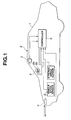
- reference numeral 1 denotes a vehicle (vehicle of interest) 1 such as an automobile, and the like, and a vehicle drive assist apparatus (ADA apparatus) 2 is mounted on the vehicle 1 to decide a possibility of collision and contact of the vehicle 1 with a preceding three-dimensional object and to give an alarm when necessary.
- ADA apparatus vehicle drive assist apparatus
- the ADA apparatus 2 generally has a deviation from lane preventing function, and the like, in addition to the collision/contact preventing function, the embodiment of the present invention will explain only the collision/contact preventing function and the explanation of the other functions will be omitted.
- the ADA apparatus 2 includes a pair of (right and left) CCD cameras 3, 3, each of which uses a solid state image pickup device, for example, a charge coupled device (CCD) and the like as a three-dimensional optical system.
- the right and left CCD cameras 3, 3 are mounted on a ceiling of a passenger compartment on the front side thereof with a predetermined interval, record an object outside of the vehicle 1 three-dimensionally from different fields of view, and input images of recorded objects to a controller 5.
- a laser projection unit 4 is mounted on the upper portion of a bumper structural member of the vehicle 1 and connected to the controller 5.
- the laser projection unit 4 includes a laser head having a function for projecting and receiving a laser beam and the function for scanning the laser beam in a right and left directions.
- the laser beam is projected from the laser projection unit 4 horizontally, and only three-dimensional objects located at positions higher than a road surface are detected therewith.
- the laser beam from the laser projection unit 4 repeats a motion for detecting distances in such a manner that it is projected and received within a predetermined range at predetermined intervals by being scanned in the right and left direction and, the two-dimensional distribution of the three-dimensional objects is measured.
- each CCD camera 3 supplies the images forward of the vehicle 1 within a horizontal range of 26° to the controller 5, whereas the laser projection unit 4 executes a scan in 80 directions at intervals of 0.15°, and supplies the data forward of the vehicle 1 within a horizontal range of 12° in every 0.1 sec. period to the controller 5, as shown in, for example, FIG. 3.
- the vehicle 1 includes a vehicle speed sensor 6 for detecting a vehicle speed V and a steering angle sensor 7 for detecting a steering angle ⁇ .
- the vehicle speed V and the steering angle 6 are supplied to the controller 5.
- the controller 5 is supplied with the images from the CCD cameras 3, the result of the scan executed by the laser projection unit 4, the vehicle speed V, and the steering angle ⁇ and independently determines the distances of a preceding three-dimensional object based on the images from the CCD cameras 3 and the result of the scan executed by the laser projection unit 4, respectively. Then, the controller 5 coordinates the data of these distances and finally determines the distance to the preceding three-dimensional object based on the coordinated data, decides a risk of the collision and a possibility of the contact of the vehicle 1 with the preceding three-dimensional object, and gives an alarm, when necessary by lighting a collision alarm lamp 8a of a combination meter 8.
- the controller 5 determines the state in which the distance to the preceding three-dimensional object is detected based on the images from the CCD cameras 3 and the state in which the distance to the preceding three-dimensional object is detected based on the result of the scan executed by the laser projection unit 4, that is, the controller 5 determines the deterioration of the detecting capabilities of the CCD cameras 3 and the laser projection unit 4. Then, when the detecting capabilities of them are deteriorated, the controller 5 notifies a driver of it by lighting a detected state display lamp 8b of the combination meter 8.
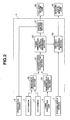
- the controller 5 is arranged to have a function as an outside of a vehicle monitor and composed of an image data processing section 5a, a laser ranging data processing section 5b, a distance data coordinating section 5c, a three-dimensional object detection processing section 5d, a distance data diagnosing section 5e, and a warning control section 5f, as shown in FIG. 2.
- the image data processing section 5a is provided as image-measured distance detection means, equally divides the image from each CCD camera 3 into 128 segments in a right and left direction, and sets an array C zln corresponding to the thus divided image. Then, the image data processing section 5a determines a typical number of dislocated pixels for each segment, calculates the distances to the three-dimensional object by the number of dislocated pixels and stores the distances as distance data measured by the image (hereinafter, referred to as "image-measured distance data”) C zln [0-127]. For example, C zln[3] shows the distance data of a segment No. 3, and when the distance data is ineffective data, it is shown by 999000.
- the laser ranging data processing section 5b is provided as laser-measured distance detection means and calculates the distance to an object by a period of time necessary from a time the laser beam is projected to a time the laser beam is received. Further, the laser ranging data processing section 5b calculates the two-dimensional position of the object (80 sections in total) from the direction in which the laser beam is projected and stores it as distance data measured by the laser beam (hereinafter, referred to as laser-measured distance data) L zln[0-79]. For example, L zln[3] shows the distance data of a segment No. 3, and when the distance data is ineffective data, it is shown by 999000.
- the distance data coordinating section 5c transforms the 80 segments of the laser-measured distance data L zln [0-79] to the coordinate of the 128 segments of the image-measured distance data (laser-measured distance data lzrzln [0-127]), and coordinates the thus transformed laser-measured distance data lzrzln [0-127] with the image-measured distance data C zln[0-127].
- a transformation of the laser-measured distance data L zln [0-79] to the laser-measured distance data lzrzln[0-127] is executed by, for example, the operation of an x-coordinate and a z-coordinate as shown below.
- x-coordinate laser-measured distance data ⁇ sink[k - kv + 50] + x-coordinate of laser head
- z-coordinate laser-measured distance data + z-coordinate of laser head
- sink[k] shows a data table of sin ((k-50) ⁇ 0.155°)
- k (laser segment number where center axis of laser head exits) - (image segment number where center axis of laser beam exists)
- "50" shows a segment No. of center of data table, and 0.155 shows one step of 80 segments of the laser beam.
- the transformed laser-measured distance data lzrzln [0-127]) is coordinated with the image-measured distance data C zln[0-127] as described below. Note that fln in [fln] shows each of 0 - 127 segments.
- the distance data based on an image has a large error when an object is located at a far distant position, whereas it has a small error when the object is located at a near position. Further, when the object is located at a very near position, the preceding object is liable to be captured beyond a rear gate. Further, the distance data based on the laser radar has a relatively small error when the object is located at the far distant position, whereas it has a large error when the object is located at the near position. Accordingly, the data to be finally employed is previously selected as described in the above items 1 to 6 so that accurate distance data can be finally obtained.
- the image-measured distance data C zln[0-127] are stored and output as zln1[0-127]
- the transformed laser-measured distance data lzrzln[0-127] are stored and output as zln2[0-127].
- coordinated final distance data zln[0-127] are output to the three-dimensional object detection processing section 5d. That is, the distance data coordinating section 5c is provided as a final distance setting means.
- the three-dimensional object detection processing section 5d eliminates the singular points at the positions less than 40 m and the singular points at the positions equal to or more than 40 m, further detects the corner points of the three-dimensional object and a corner-shaped three-dimensional object based on the result of previous detection of the three-dimensional object, and recognizes the three-dimensional object by subjecting the final distance data zln[0-127] to a grouping processing. Accordingly, three-dimensional object recognition means is composed of the distance data coordinating section 5c and the three-dimensional object detection processing section 5d.
- the three-dimensional object detection processing section 5d eliminates distant three-dimensional objects, which are located between three-dimensional sections having approximately the same distance from the vehicle 1, as the singular points in such a situation that the three-dimensional objects are complicatedly mixed and the distant three-dimensional objects can be observed from between near three-dimensional objects.
- the three-dimensional object detection processing section 5d sets the final distance data zln[fln], which are located at a position less than 40 m, as a reference point P0 (z0, x0), and determines the point, which satisfies all of the following conditions, as the point having the same distance, and eliminates distant points located between these two points as the singular points. Note that the distance data of the points to be eliminated are substituted by 999000 similarly to ineffective data.
- points P4 and P5 which exist in a hatched region, are recognized as the points located at equal distances with respect to the reference point P0.
- the z-direction and the x-direction of the hatched region are set, for example, as shown below.
- points P1 and P2 located at positions farther than the hatched region are eliminated as the singular points, whereas a point P3 located at the position nearer than the hatched region is not eliminated.
- the singular points of the final distance data zln[fln] located at the position less than 40 m are eliminated regardless of whether the distance data is based on the image or based on the laser radar, thereby data processing is simplified.
- the distance data measured by the laser radar shows the right and left reflectors of the preceding vehicle. Accordingly, the distance data of an image located between the right and left reflectors is eliminated as the singular point.
- the laser radar detects the distance mainly by the reflectors of the preceding vehicle.
- the three-dimensional object can be recognized accurately and promptly by eliminating the distance data, which exists between the distance data measured by the laser radar, of a more distant image as the singular point when it is determined that the distance data is not necessary or that it has a large error.
- the three-dimensional object detection processing section 5d provides a survey area using the corner point of a corner-shaped three-dimensional object detected last time as the center of the survey area and examines the final distance data zln[0-127] from which the singular points detected this time as described above are eliminated to thereby detect whether or not a new corner point exists.
- the three-dimensional object detection processing section 5d groups the data, that is, determines a threshold value, groups zln [fln] in the threshold value, extracts side wall data from the inclination, and the like of the grouped data, and detect the three-dimensional object and a side wall by dividing and coordinating the grouped data.
- the information of the detected three-dimensional object is supplied to the distance data diagnosing section 5e and to the warning control section 5f.
- the distance data diagnosing section 5e determines whether the finally detected three-dimensional object is detected in both the image-measured distance data C zln[0-127] (zln1[0-127]) and the transformed laser-measured distance data lzrzln[0-127] (zln2[0-127]). When the finally detected three-dimensional object is not detected by the image-measured distance data zln1[0-127], the distance data diagnosing section 5e determines that a capability for measuring a distance by the image is deteriorated and notifies the driver of it by lighting the detected state display lamp 8b of the combination meter 8 as prescribed.
- the distance data diagnosing section 5e determines that the capability for measuring the distance by the laser is deteriorated and notifies the driver of it by lighting the detected state display lamp 8b of the combination meter 8 as prescribed.
- the distance measuring capability is determined when the vehicle 1 travels on an approximately straight road at a steering angle of -10° to +10°. This is because when the distance is measured by a laser radar, it is difficult to recognize the three-dimensional object because a laser beam is projected at an inclined angle and cannot be reflected, while a guard rail and a side wall can be recognized when the distance is measured by the image.
- the survey area of the three-dimensional object in which the distance measuring capability is determined is set in an area where the field of view of the laser radar overlaps that of the image, and the three-dimensional object, which exists 40 to 70 m ahead of the vehicle 1 and has a width of 50 cm or more, is used as the three-dimensional object for determining the distance measuring capability.
- the reason why the three-dimensional object existing 40 to 70 m ahead of the vehicle 1 is used resides in that when the three-dimensional object existing farther than the above distances is also used for the determination, the error of the distance data obtained by the image and the error of the distance data obtained by the laser radar are increased.
- the distance measuring capability cannot be determined by the distance data of a forward three-dimensional object locating at a position less than 40 m ahead of the vehicle 1 because the deterioration of the distance measuring capability of the three-dimensional object is very small.
- the reason why the three-dimensional object having the width of 50 cm or more is used resides in that when there are a plurality of the preceding vehicles, the three-dimensional object may erroneously recognized in a vacant space between the three-dimensional objects in the image.
- the distance data diagnosing section 5e determines whether or not the image-measured distance data zln1[0-127] exists with respect to the three-dimensional object, and when the image-measured distance data does not exist, the three-dimensional object is counted to the number of the three-dimensional objects without image n1. Likewise, the distance data diagnosing section 5e determines whether or not the laser-measured distance data zln2[0-127] exists with respect to the three-dimensional object, and when the laser-measured distance data does not exist, the three-dimensional object is counted to the number of the three-dimensional objects without a laser n2.
- the distance data diagnosing section 5e increments an image capability determination timer, whereas when it is less than the detection ratio threshold value k6, the distance data diagnosing section 5e decrements the image capability determination timer.
- the distance data diagnosing section 5e determines that the distance measuring capability of image is deteriorated and lights the detected state display lamp 8b as prescribed.
- the distance data diagnosing section 5e extinguishes the detected state display lamp 8b being lit.
- the distance data diagnosing section 5e increments a laser radar capability determination timer, whereas when it is less than the detection ratio threshold value k5, the distance data diagnosing section 5e decrements the laser radar capability determination timer.
- the distance data diagnosing section 5e determines that the distance measuring capability of the laser radar is deteriorated and lights the detected state display lamp 8b as prescribed.
- the distance data diagnosing section 5e extinguishes the detected state display lamp 8b being lit.
- the deterioration of the distance measuring capabilities of the image and the laser radar is determined depending on whether or not there are the distance data of the image and the laser radar that detect a finally detected three-dimensional object in this embodiment. Accordingly, it is possible to promptly and accurately determine the deterioration of the distance measuring capabilities of the image and the laser radar.
- the warning control section 5f extracts other vehicles, obstructs, and the like existing on the right and left lanes adjacent to the lane of the vehicle 1 based on the three-dimensional object information from the three-dimensional object detection processing section 5d, the vehicle speeds V from the vehicle speed sensor 6, and the like. Then, the warning control section 5f decides the possibility of the collision and contact of the other vehicles, the obstacles, and the like with the vehicle 1 from the positions and sizes of the thus extracted objects, the relative speeds of them to the vehicle 1 determined from the positional changes with time, and the like. As a result, the warning control section 5f gives the alarm when necessary by lighting the collision alarm lamp 8a of the combination meter 8.
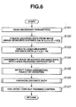
- FIG. 6 is a flowchart showing the overall flow of the forward monitor program.
- S necessary parameters are read at step 101.
- a process goes to S102 and creates the grouping data (image-measured distance data C zln[0-127]) from the image. That is, the image data processing section 5a equally divides the image from each CCD camera 3 into 128 segments in a right and left direction as shown in FIG. 4, and sets an array C zln corresponding to the segments. Then, the image data processing section 5a determines a typical number of dislocated pixels for each segment, calculates the distance to the three-dimensional object from the number of dislocated pixels and stores the distance as image-measured distance data C zln[0-127]. For example, C zln[3] shows the distance data of a segment No. 3, and when the distance data are ineffective data, it is shown by 999000.
- the process goes to S103, and the laser ranging data processing section 5b creates laser-measured distance data L zln[0-79]. That is, the laser ranging data processing section 5b calculates the distance to the object by a period of time necessary from a time a laser beam is projected to a time the laser beam is received. Further, the laser ranging data processing section 5b calculates the two-dimensional position (80 segments in total) of the object from a direction where the laser beam is projected. For example, L zln[3] shows the distance data of the segment No. 3, and when the distance data is ineffective data, it is shown by 999000.
- the distance data coordinating section 5c transforms the 80 segments of the laser-measured distance data L zln[0-79] to the coordinate of the 128 segments of image-measured distance data (laser-measured distance data lzrzln[0-127]).
- the laser-measured distance data L zln[0-79] is transformed to the laser-measured distance data lzrzln[0-127] by, for example, Equations (1) and (2) described above.
- the process goes to S202 and stores the image-measured distance data C zln[0-127] as zln1[0-127] and stores the transformed laser-measured distance data lzrzln[0-127] as zln2[0-127], and then the process goes to S203.
- the process goes to S205 and determines whether or not the laser-measured distance data lzrzln[fln] is located at a long distance position (20 m or more).
- the process goes to S206 and determines whether or not the laser-measured distance data lzrzln[fln] is located at an intermediate distance position (10 m or more to less than 20 m).
- the process goes to S207 and determines whether or not the laser-measured distance data lzrzln[fln] is located at a short distance position (3 m or more to less than 10 m) or at a very short distance position (less than 3 m).
- the process goes to S209 and determines whether or not the image-measured distance data C zln[fln] is effective.
- the process goes to S210 and determines whether or not the difference between the image-measured distance data C zln[fln] and the laser-measured distance data lzrzln[fln] is equal to or less than 2.5 m.
- the process goes to S212 and determines whether or not the coordinate processing is completed to the laser-measured distance data lzrzln[fln] of all the 128 segments from 0 to 127.
- the process escapes from the routine, whereas when the coordinate processing is not completed, the processing steps from S203 to S211 described above are repeated to the following segments.
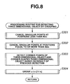
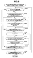
- step S105 After the image-measured distance data is coordinated with the laser-measured distance data at S104 described above, the process goes to step S105 and detects a three-dimensional object by the grouping shown in FIG. 8.
- the three-dimensional object detection processing section 5d eliminates the singular points located at positions less than 40 m at step S301. That is, the distant three-dimensional objects, which are located between the three-dimensional sections having approximately the same distance from the vehicle 1, are eliminated as the singular points in such a situation that the three-dimensional objects are complicatedly mixed and the distant three-dimensional objects are observed from between near three-dimensional objects. As shown in FIG.
- the final distance data zln[fln] which is located at a position less than 40 m, is set as a reference point P0 (z0, x0), and the point, which satisfies all of the following conditions, is determined as a point having the same distance, and the distant points between these two points are eliminated as the singular points.
- the distance data of the points to be eliminated is substituted by 999000 similarly to the ineffective data.
- the singular points of the final distance data zln[fln] located at the position less than 40 m are eliminated regardless of whether the distance data is based on an image or based on a laser radar, thereby data processing is simplified.
- step S302 the process goes to step S302 and eliminates the singular points located at the positions of 40 m or more as shown in FIG. 9 which will be described later.
- the process goes to S303, at which the three-dimensional object detection processing section 5d sets a survey area using the corner point of the corner-shaped three-dimensional object detected last time as the center of the survey area, and examines the final distance data zln[0-127], which is detected this time and from which the singular points are eliminated at S301 and S302, to thereby detect whether or not a new corner point exists.
- the process goes to S304, at which the three-dimensional object detection processing section 5d groups the data, that is, determines a threshold value, groups the final distance data zln[fln] that exists in the threshold value, extracts side wall data from the inclination, and the like of the grouped data, and divides and coordinates the grouped data to thereby detect the three-dimensional object and a side wall.
- the processing step executed at S302 for eliminating the singular points located at the positions of 40 m or more first, it is determined at S401 whether or not the distance data zln[fls] of the segments to be handled is the data of 40 m or more as well as whether or not the laser-measured distance data lzrzln[fls] of the segments is effective.
- [fls] shows the segments of data to be handled, and the data is divided into 128 segments from 0 to 127 in correspondence to S410 that will be described later.
- the process jumps to S410 when the result of the determination at S401 shows at least any one of that the distance data zln[fls] is less than 40 m and that the laser-measured distance data lzrzln[fls] of the segments is ineffective. Then, it is determined at step 410 whether or not the processing of the distance data zln[fls] of all the 128 segments from 0 to 127 to be handled is completed. When the processing is completed, the process escapes from the routine, whereas when it is not completed, the processing steps from S401 are executed again as to the following segments.
- the process goes to S402 and determines a survey area using the laser-measured distance data lzrzln[fls] of the segments as a reference, and the segment is set to the segment zln[fle] of the survey area at the other end thereof in correspondence to the position spaced apart from the data zln[fls] by 2 m in the right direction.
- the process goes to S403 and determines whether or not the difference of the distance to zln[fls] is 0.5 m or less in the survey area of the segments from zln[fls] to zln[fle] (that is,
- the process goes to S406 and determines whether or not the right end segment data zln[f0] corresponding to zln[fls] is set.
- the process jumps to S410 and determines the processing steps of the distance data zln[fls] of all the 128 segments to be handled from 0 to 127 are completed.
- the process escapes from the routine, whereas when they are not completed, the processing steps from S401 are executed again as to the following segments.
- step S407 it is determined whether or not the distance data zln[fln] is located at the position farther than zln[fls] + 0.5 m as well as whether or not the laser-measured distance data lzrzln[fln] thereof is ineffective in the data of the segments from "fls + 1" to "f0 - 1" (segments from "fls" to "f0").
- the laser radar detects the distance mainly by the reflectors of the preceding vehicle. Accordingly, in this embodiment, the three-dimensional object can be recognized accurately and promptly by eliminating the distance data, which exists between the distance data measured by the laser radar, of a more distant image as the singular point when it is determined that the distance data is not necessary or that it has a large error.
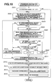
- the process goes to S106 and executes the distance data diagnosis processing shown in FIG. 10.
- step S501 it is determined at step S501 whether or not the vehicle 1 travels on an approximately straight road at the steering angle set to -10° to 10°.
- the steering angle is larger than -10° to 10°, no diagnosis processing is executed, and the process escapes from the routine as it is. This is because when the distance is measured with the laser beam, it is difficult to recognize the three-dimensional object because it is projected at the inclined angle and cannot be reflected thereby, and thus an accurate result of the diagnosis processing cannot be obtained, while a guard rail and the side wall can be recognized when the distance is measured with an image.
- the process goes to S502 and sets the initial value of the total number of the three-dimensional objects to be subjected to determination to n0, the initial value of the number of the three-dimensional objects without image to n1 and the initial value of the number of the three-dimensional objects without the laser radar to n2.
- the process goes to S503 and determines whether or not the three-dimensional object is to be diagnosed. This determination is made depending upon whether or not the three-dimensional object is located at a portion where the field of view of the laser radar overlaps the field of view of the image and depending upon whether or not the three-dimensional object exists 40 to 70 m ahead of the vehicle 1 and has a width of 50 cm or more.
- the process jumps to S510 and determines not to diagnose the three-dimensional object.
- the process goes to S506 and determines whether or not there is the image-measured distance data zln1 corresponding to the three-dimensional object as well as whether or not there is no laser-measured distance data zln2 corresponding to the three-dimensional object.
- the process goes to S508 and determines whether or not there is no image-measured distance data zln1 corresponding to the three-dimensional object as well as whether or not there is the laser-measured distance data zln2 corresponding to the three-dimensional object.
- the process goes to S510 and excludes the three-dimensional object from the subject to be diagnosed.
- the process goes to S511 and determines whether or not the determination is executed to all the three-dimensional objects, and when all the three-dimensional objects are not subjected to the determination, the process returns to S503 and repeats the processing steps described above.
- the process goes to S513 and increments the image capability determination timer when the three-dimensional object non-detection ratio of the image is equal to or larger than the preset detecting ratio threshold value k6, whereas when it is less than the detection ratio threshold value k6, the image capability determination timer is decremented.
- the laser radar capability determination timer is incremented, whereas when it is less than the detection ratio threshold value k5, the laser radar capability determination timer is decremented.
- the process goes to S514 and determines whether or not the value of the image capability determination timer exceeds the preset output threshold value k1.
- the process goes to S515 and lights the detected state display lamp 8b as prescribed by deciding that the distance measuring capability of image is deteriorated.
- the process goes to S515 and extinguishes the detected state display lamp 8b being lit.
- the process goes to S514 and determines whether or not the value of the laser radar capability determination timer exceeds the preset output threshold value k3.
- the process goes to S515 and lights the detected state display lamp 8b as prescribed by deciding that the distance measuring capability of the laser radar is deteriorated.
- the process goes to S515 and extinguishes the detected state display lamp 8b being lit.
- the deterioration of the distance measuring capabilities of the image and the laser radar is determined depending on whether or not there is the distance data of the image and the distance data of the laser radar that have detected the finally detected three-dimensional object. Accordingly, it is possible to promptly and accurately determine the deterioration of the distance measuring capabilities of the image and the laser radar.
- the three-dimensional object is diagnosed simply depending upon whether or not there is the image-measured distance data zln1 or the laser-measured distance data zln2.
- the three-dimensional object can be also simply diagnosed by another method, for example, by comparing the difference between the three-dimensional object to be diagnosed and the image-measured distance data zln1 with the difference between the three-dimensional object to be diagnosed and the laser-measured distance data distance data zln2.
- the process goes to S107 and executes a collision/contact alarm control. That is, other vehicles, obstacles, and the like existing on the right and left lanes adjacent to the lane of the vehicle 1 are extracted on the basis of the information of the three-dimensional objects from the three-dimensional object detection processing section 5d, the vehicle speeds V from the vehicle speed sensor 6, and the like, the possibility of the collision and the contact of them with the vehicle 1 is decided from the sizes of the detected objects, the relative speeds of them to the vehicle 1 determined from the positional changes with the time, and the alarm is given by lighting the collision alarm lamp 8a of the combination meter 8 according to the result of decision, when necessary.
- the three-dimensional object existing in front of the vehicle 1 can be promptly and accurately recognized based on the information from the image and the information from the laser radar without executing unnecessary processing.
Landscapes
- Engineering & Computer Science (AREA)
- Physics & Mathematics (AREA)
- Radar, Positioning & Navigation (AREA)
- Remote Sensing (AREA)
- General Physics & Mathematics (AREA)
- Electromagnetism (AREA)
- Computer Networks & Wireless Communication (AREA)
- Computer Vision & Pattern Recognition (AREA)
- Geometry (AREA)
- Theoretical Computer Science (AREA)
- Optical Radar Systems And Details Thereof (AREA)
- Traffic Control Systems (AREA)
- Length Measuring Devices By Optical Means (AREA)
- Measurement Of Optical Distance (AREA)
- Fittings On The Vehicle Exterior For Carrying Loads, And Devices For Holding Or Mounting Articles (AREA)
- Closed-Circuit Television Systems (AREA)
Applications Claiming Priority (2)
| Application Number | Priority Date | Filing Date | Title |
|---|---|---|---|
| JP2001338094 | 2001-11-02 | ||
| JP2001338094A JP3880837B2 (ja) | 2001-11-02 | 2001-11-02 | 車外監視装置 |
Publications (2)
| Publication Number | Publication Date |
|---|---|
| EP1308752A2 true EP1308752A2 (fr) | 2003-05-07 |
| EP1308752A3 EP1308752A3 (fr) | 2003-11-26 |
Family
ID=19152636
Family Applications (1)
| Application Number | Title | Priority Date | Filing Date |
|---|---|---|---|
| EP02024447A Withdrawn EP1308752A3 (fr) | 2001-11-02 | 2002-10-29 | Système de surveillance de l'extérieur d'un véhicule et méthode là-dessous |
Country Status (3)
| Country | Link |
|---|---|
| US (1) | US6823261B2 (fr) |
| EP (1) | EP1308752A3 (fr) |
| JP (1) | JP3880837B2 (fr) |
Cited By (4)
| Publication number | Priority date | Publication date | Assignee | Title |
|---|---|---|---|---|
| WO2012107067A1 (fr) * | 2011-02-10 | 2012-08-16 | Daimler Ag | Véhicule équipé d'un dispositif de détection d'un environnement du véhicule |
| CN104931956A (zh) * | 2015-06-29 | 2015-09-23 | 中国船舶重工集团公司第七二四研究所 | 一种基于圆概率误差加权的多雷达分组协同定位处理方法 |
| CN111694010A (zh) * | 2020-05-27 | 2020-09-22 | 东南大学 | 一种基于视觉与激光雷达融合的路侧车辆识别方法 |
| CN113496491A (zh) * | 2020-03-19 | 2021-10-12 | 广州汽车集团股份有限公司 | 一种基于多线激光雷达的路面分割方法及装置 |
Families Citing this family (114)
| Publication number | Priority date | Publication date | Assignee | Title |
|---|---|---|---|---|
| US5877897A (en) | 1993-02-26 | 1999-03-02 | Donnelly Corporation | Automatic rearview mirror, vehicle lighting control and vehicle interior monitoring system using a photosensor array |
| US5910854A (en) | 1993-02-26 | 1999-06-08 | Donnelly Corporation | Electrochromic polymeric solid films, manufacturing electrochromic devices using such solid films, and processes for making such solid films and devices |
| US6822563B2 (en) | 1997-09-22 | 2004-11-23 | Donnelly Corporation | Vehicle imaging system with accessory control |
| US5668663A (en) | 1994-05-05 | 1997-09-16 | Donnelly Corporation | Electrochromic mirrors and devices |
| US6891563B2 (en) | 1996-05-22 | 2005-05-10 | Donnelly Corporation | Vehicular vision system |
| US7655894B2 (en) | 1996-03-25 | 2010-02-02 | Donnelly Corporation | Vehicular image sensing system |
| US6172613B1 (en) | 1998-02-18 | 2001-01-09 | Donnelly Corporation | Rearview mirror assembly incorporating vehicle information display |
| US6326613B1 (en) | 1998-01-07 | 2001-12-04 | Donnelly Corporation | Vehicle interior mirror assembly adapted for containing a rain sensor |
| US8294975B2 (en) | 1997-08-25 | 2012-10-23 | Donnelly Corporation | Automotive rearview mirror assembly |
| US6124886A (en) | 1997-08-25 | 2000-09-26 | Donnelly Corporation | Modular rearview mirror assembly |
| US8288711B2 (en) | 1998-01-07 | 2012-10-16 | Donnelly Corporation | Interior rearview mirror system with forwardly-viewing camera and a control |
| US6445287B1 (en) | 2000-02-28 | 2002-09-03 | Donnelly Corporation | Tire inflation assistance monitoring system |
| US6329925B1 (en) | 1999-11-24 | 2001-12-11 | Donnelly Corporation | Rearview mirror assembly with added feature modular display |
| US6477464B2 (en) | 2000-03-09 | 2002-11-05 | Donnelly Corporation | Complete mirror-based global-positioning system (GPS) navigation solution |
| US6693517B2 (en) | 2000-04-21 | 2004-02-17 | Donnelly Corporation | Vehicle mirror assembly communicating wirelessly with vehicle accessories and occupants |
| US7167796B2 (en) | 2000-03-09 | 2007-01-23 | Donnelly Corporation | Vehicle navigation system for use with a telematics system |
| WO2001064481A2 (fr) | 2000-03-02 | 2001-09-07 | Donnelly Corporation | Systeme de miroir video integrant un module accessoire |
| US7195381B2 (en) | 2001-01-23 | 2007-03-27 | Donnelly Corporation | Vehicle interior LED lighting system |
| US7370983B2 (en) | 2000-03-02 | 2008-05-13 | Donnelly Corporation | Interior mirror assembly with display |
| US7255451B2 (en) | 2002-09-20 | 2007-08-14 | Donnelly Corporation | Electro-optic mirror cell |
| US7581859B2 (en) | 2005-09-14 | 2009-09-01 | Donnelly Corp. | Display device for exterior rearview mirror |
| JP2003121547A (ja) * | 2001-10-18 | 2003-04-23 | Fuji Heavy Ind Ltd | 車外監視装置 |
| US6918674B2 (en) | 2002-05-03 | 2005-07-19 | Donnelly Corporation | Vehicle rearview mirror system |
| AU2003225228A1 (en) | 2002-05-03 | 2003-11-17 | Donnelly Corporation | Object detection system for vehicle |
| US7329013B2 (en) | 2002-06-06 | 2008-02-12 | Donnelly Corporation | Interior rearview mirror system with compass |
| WO2003105099A1 (fr) | 2002-06-06 | 2003-12-18 | Donnelly Corporation | Systeme de miroir de courtoisie interieur a boussole |
| JP4176430B2 (ja) * | 2002-09-18 | 2008-11-05 | 富士重工業株式会社 | 車外監視装置、及び、この車外監視装置を備えた走行制御装置 |
| US7310177B2 (en) | 2002-09-20 | 2007-12-18 | Donnelly Corporation | Electro-optic reflective element assembly |
| US7274501B2 (en) | 2002-09-20 | 2007-09-25 | Donnelly Corporation | Mirror reflective element assembly |
| JP3998601B2 (ja) * | 2002-10-09 | 2007-10-31 | 富士通株式会社 | パルスレーダ装置 |
| JP3862015B2 (ja) * | 2002-10-25 | 2006-12-27 | オムロン株式会社 | 車載用レーダ装置 |
| US7289037B2 (en) | 2003-05-19 | 2007-10-30 | Donnelly Corporation | Mirror assembly for vehicle |
| JP4265931B2 (ja) * | 2003-05-22 | 2009-05-20 | 富士重工業株式会社 | 先行車両検出装置 |
| JP2005025692A (ja) * | 2003-07-04 | 2005-01-27 | Suzuki Motor Corp | 車両用情報提供装置 |
| US7046190B2 (en) * | 2003-07-25 | 2006-05-16 | Raytheon Company | Process for phase-derived range measurements |
| US20050024260A1 (en) * | 2003-07-30 | 2005-02-03 | Johnston Gary P. | E-field monitor for broadband pulsed |
| US6906663B2 (en) * | 2003-07-30 | 2005-06-14 | The Boeing Company | E-field monitor for pulsed signals |
| US6882302B1 (en) * | 2003-09-22 | 2005-04-19 | Rockwell Collins | Enhanced adaptive weather thresholds for identification of hazards system and method |
| US7446924B2 (en) | 2003-10-02 | 2008-11-04 | Donnelly Corporation | Mirror reflective element assembly including electronic component |
| US7038615B2 (en) * | 2003-10-10 | 2006-05-02 | Raytheon Company | Efficient technique for estimating elevation angle when using a broad beam for search in a radar |
| US6977610B2 (en) * | 2003-10-10 | 2005-12-20 | Raytheon Company | Multiple radar combining for increased range, radar sensitivity and angle accuracy |
| US7308341B2 (en) | 2003-10-14 | 2007-12-11 | Donnelly Corporation | Vehicle communication system |
| JP4763250B2 (ja) * | 2004-04-09 | 2011-08-31 | 株式会社デンソー | 物体検出装置 |
| US7526103B2 (en) | 2004-04-15 | 2009-04-28 | Donnelly Corporation | Imaging system for vehicle |
| US7561720B2 (en) * | 2004-04-30 | 2009-07-14 | Visteon Global Technologies, Inc. | Single camera system and method for range and lateral position measurement of a preceding vehicle |
| US7881496B2 (en) | 2004-09-30 | 2011-02-01 | Donnelly Corporation | Vision system for vehicle |
| EP1839290B1 (fr) | 2004-12-01 | 2013-08-21 | Zorg Industries (Hong Kong) Limited | Systeme integre pour vehicule permettant d'eviter des chocs a faible vitesse |
| DE102005002636A1 (de) * | 2005-01-12 | 2006-08-10 | Valeo Schalter Und Sensoren Gmbh | Verfahren und System zur Verarbeitung von Videodaten eines Kamerasystems |
| US7561721B2 (en) * | 2005-02-02 | 2009-07-14 | Visteon Global Technologies, Inc. | System and method for range measurement of a preceding vehicle |
| EP1883855B1 (fr) | 2005-05-16 | 2011-07-20 | Donnelly Corporation | Ensemble de retroviseur de vehicule comportant des informations sur l'element reflecteur |
| WO2006123615A1 (fr) * | 2005-05-19 | 2006-11-23 | Olympus Corporation | Appareil, procede et programme de mesure de la distance |
| US20070031008A1 (en) * | 2005-08-02 | 2007-02-08 | Visteon Global Technologies, Inc. | System and method for range measurement of a preceding vehicle |
| US7706978B2 (en) * | 2005-09-02 | 2010-04-27 | Delphi Technologies, Inc. | Method for estimating unknown parameters for a vehicle object detection system |
| CN101535087B (zh) | 2005-11-01 | 2013-05-15 | 唐纳利公司 | 具有显示装置的内部后视镜 |
| DE102005056265A1 (de) | 2005-11-14 | 2007-05-16 | Pilz Gmbh & Co Kg | Vorrichtung und Verfahren zum Überwachen eines Raumbereichs, insbesondere zum Absichern eines Gefahrenbereichs einer automatisiert arbeitenden Anlage |
| US7623681B2 (en) * | 2005-12-07 | 2009-11-24 | Visteon Global Technologies, Inc. | System and method for range measurement of a preceding vehicle |
| JP5577038B2 (ja) | 2006-03-09 | 2014-08-20 | ジェンテックス コーポレイション | 高輝度ディスプレイを含む車両リアビューアセンブリ |
| WO2008024639A2 (fr) | 2006-08-11 | 2008-02-28 | Donnelly Corporation | Système de commande automatique de phare de véhicule |
| US20090005948A1 (en) * | 2007-06-28 | 2009-01-01 | Faroog Abdel-Kareem Ibrahim | Low speed follow operation and control strategy |
| JP2009047498A (ja) * | 2007-08-17 | 2009-03-05 | Fujifilm Corp | 立体撮像装置および立体撮像装置の制御方法並びにプログラム |
| JP2009047495A (ja) * | 2007-08-17 | 2009-03-05 | Fujifilm Corp | 立体撮像装置および立体撮像装置の制御方法並びにプログラム |
| JP5590774B2 (ja) * | 2008-03-28 | 2014-09-17 | トヨタ自動車株式会社 | 物体検出装置 |
| US8154418B2 (en) | 2008-03-31 | 2012-04-10 | Magna Mirrors Of America, Inc. | Interior rearview mirror system |
| JP4557041B2 (ja) * | 2008-04-18 | 2010-10-06 | 株式会社デンソー | 車両用画像処理装置 |
| JP5283967B2 (ja) * | 2008-05-14 | 2013-09-04 | 日立オートモティブシステムズ株式会社 | 車載用物体検知装置 |
| US8755997B2 (en) * | 2008-07-30 | 2014-06-17 | Honeywell International Inc. | Laser ranging process for road and obstacle detection in navigating an autonomous vehicle |
| US8452078B2 (en) * | 2008-10-15 | 2013-05-28 | Toyota Motor Engineering & Manufacturing North America | System and method for object recognition and classification using a three-dimensional system with adaptive feature detectors |
| US9487144B2 (en) | 2008-10-16 | 2016-11-08 | Magna Mirrors Of America, Inc. | Interior mirror assembly with display |
| US8364334B2 (en) * | 2008-10-30 | 2013-01-29 | Honeywell International Inc. | System and method for navigating an autonomous vehicle using laser detection and ranging |
| US8044781B2 (en) | 2008-11-10 | 2011-10-25 | Volkswagen Ag | System and method for displaying a 3D vehicle surrounding with adjustable point of view including a distance sensor |
| US8687898B2 (en) * | 2010-02-01 | 2014-04-01 | Toyota Motor Engineering & Manufacturing North America | System and method for object recognition based on three-dimensional adaptive feature detectors |
| JP2012183867A (ja) * | 2011-03-03 | 2012-09-27 | Fuji Heavy Ind Ltd | 車両の運転支援装置 |
| JP5580233B2 (ja) * | 2011-03-22 | 2014-08-27 | 富士重工業株式会社 | 車外監視装置および車外監視方法 |
| US8799201B2 (en) | 2011-07-25 | 2014-08-05 | Toyota Motor Engineering & Manufacturing North America, Inc. | Method and system for tracking objects |
| US10457209B2 (en) | 2012-02-22 | 2019-10-29 | Magna Electronics Inc. | Vehicle vision system with multi-paned view |
| US9319637B2 (en) | 2012-03-27 | 2016-04-19 | Magna Electronics Inc. | Vehicle vision system with lens pollution detection |
| US8879139B2 (en) | 2012-04-24 | 2014-11-04 | Gentex Corporation | Display mirror assembly |
| US9707896B2 (en) | 2012-10-15 | 2017-07-18 | Magna Electronics Inc. | Vehicle camera lens dirt protection via air flow |
| JP2014145731A (ja) * | 2013-01-30 | 2014-08-14 | Toyota Motor Corp | 物標検出装置及び物標検出方法 |
| US9445057B2 (en) | 2013-02-20 | 2016-09-13 | Magna Electronics Inc. | Vehicle vision system with dirt detection |
| WO2014150188A1 (fr) | 2013-03-15 | 2014-09-25 | Gentex Corporation | Ensemble de miroir d'affichage |
| JP6197388B2 (ja) * | 2013-06-11 | 2017-09-20 | 富士通株式会社 | 距離測定装置、距離測定方法、およびプログラム |
| JP2016534915A (ja) | 2013-09-24 | 2016-11-10 | ジェンテックス コーポレイション | 表示ミラーアセンブリ |
| US9835642B2 (en) * | 2013-11-08 | 2017-12-05 | The Johns Hopkins University | High speed image processing device |
| US9511715B2 (en) | 2014-01-31 | 2016-12-06 | Gentex Corporation | Backlighting assembly for display for reducing cross-hatching |
| EP3119643B1 (fr) | 2014-03-21 | 2018-05-23 | Gentex Corporation | Ensemble miroir d'affichage trimodal |
| EP3126195B1 (fr) | 2014-04-01 | 2019-06-05 | Gentex Corporation | Ensemble miroir d'affichage automatique |
| WO2016044746A1 (fr) | 2014-09-19 | 2016-03-24 | Gentex Corporation | Ensemble rétroviseur |
| US9694752B2 (en) | 2014-11-07 | 2017-07-04 | Gentex Corporation | Full display mirror actuator |
| KR101977685B1 (ko) | 2014-11-13 | 2019-05-13 | 젠텍스 코포레이션 | 디스플레이를 갖춘 후방 미러 시스템 |
| CN107107825B (zh) | 2014-12-03 | 2020-08-21 | 金泰克斯公司 | 用于车辆的显示镜组件 |
| USD746744S1 (en) | 2014-12-05 | 2016-01-05 | Gentex Corporation | Rearview device |
| US9744907B2 (en) | 2014-12-29 | 2017-08-29 | Gentex Corporation | Vehicle vision system having adjustable displayed field of view |
| US9720278B2 (en) | 2015-01-22 | 2017-08-01 | Gentex Corporation | Low cost optical film stack |
| JP2018513810A (ja) | 2015-04-20 | 2018-05-31 | ジェンテックス コーポレイション | 装飾を備えた後方視認アセンブリ |
| US10112540B2 (en) | 2015-05-18 | 2018-10-30 | Gentex Corporation | Full display rearview device |
| KR102135427B1 (ko) | 2015-06-22 | 2020-07-17 | 젠텍스 코포레이션 | 진폭-변조된 광의 깜박임을 보정하기 위해 스트리밍된 비디오 이미지를 처리하는 시스템 및 방법 |
| EP3368374B1 (fr) | 2015-10-30 | 2023-12-27 | Gentex Corporation | Manette à bascule |
| USD797627S1 (en) | 2015-10-30 | 2017-09-19 | Gentex Corporation | Rearview mirror device |
| USD798207S1 (en) | 2015-10-30 | 2017-09-26 | Gentex Corporation | Rearview mirror assembly |
| US9994156B2 (en) | 2015-10-30 | 2018-06-12 | Gentex Corporation | Rearview device |
| USD800618S1 (en) | 2015-11-02 | 2017-10-24 | Gentex Corporation | Toggle paddle for a rear view device |
| USD845851S1 (en) | 2016-03-31 | 2019-04-16 | Gentex Corporation | Rearview device |
| USD817238S1 (en) | 2016-04-29 | 2018-05-08 | Gentex Corporation | Rearview device |
| US10025138B2 (en) | 2016-06-06 | 2018-07-17 | Gentex Corporation | Illuminating display with light gathering structure |
| CN106249251B (zh) * | 2016-08-31 | 2019-08-30 | 深圳市速腾聚创科技有限公司 | 三维激光雷达系统 |
| USD809984S1 (en) | 2016-12-07 | 2018-02-13 | Gentex Corporation | Rearview assembly |
| USD854473S1 (en) | 2016-12-16 | 2019-07-23 | Gentex Corporation | Rearview assembly |
| WO2018125898A1 (fr) | 2016-12-30 | 2018-07-05 | Gentex Corporation | Miroir à affichage complet avec vue d'observateur à la demande |
| EP3595931A1 (fr) | 2017-03-17 | 2020-01-22 | Gentex Corporation | Système de caméra arrière à double affichage |
| KR102050632B1 (ko) * | 2017-08-02 | 2019-12-03 | 주식회사 에스오에스랩 | 다채널 라이다 센서 모듈 |
| DE102018122263B4 (de) * | 2018-09-12 | 2021-03-18 | Sick Ag | Autonomes Fahrzeug |
| JP7298350B2 (ja) * | 2019-07-08 | 2023-06-27 | 株式会社リコー | 測距装置、情報処理装置、測距方法、車載装置、移動体、測距システム |
| JP7766227B2 (ja) | 2021-08-20 | 2025-11-10 | ジェンテックス コーポレイション | 照明アセンブリ及び照明アセンブリを有する照射システム |
Family Cites Families (14)
| Publication number | Priority date | Publication date | Assignee | Title |
|---|---|---|---|---|
| JPH05265547A (ja) * | 1992-03-23 | 1993-10-15 | Fuji Heavy Ind Ltd | 車輌用車外監視装置 |
| JP3263699B2 (ja) * | 1992-12-22 | 2002-03-04 | 三菱電機株式会社 | 走行環境監視装置 |
| JPH06221815A (ja) * | 1993-01-25 | 1994-08-12 | Daihatsu Motor Co Ltd | スキャンレーザレーダによる先行車両認識方法 |
| JP3367170B2 (ja) * | 1993-11-05 | 2003-01-14 | 株式会社豊田中央研究所 | 障害物検出装置 |
| JP3212218B2 (ja) * | 1994-05-26 | 2001-09-25 | 三菱電機株式会社 | 車両用障害物検出装置 |
| JP3401913B2 (ja) * | 1994-05-26 | 2003-04-28 | 株式会社デンソー | 車両用障害物認識装置 |
| JP3240835B2 (ja) * | 1994-06-09 | 2001-12-25 | 株式会社日立製作所 | 車両用距離計測装置 |
| JP3866328B2 (ja) * | 1996-06-06 | 2007-01-10 | 富士重工業株式会社 | 車両周辺立体物認識装置 |
| JP3805832B2 (ja) * | 1996-07-10 | 2006-08-09 | 富士重工業株式会社 | 車両用運転支援装置 |
| JP3866349B2 (ja) * | 1996-12-27 | 2007-01-10 | 富士重工業株式会社 | 車両の衝突防止装置 |
| JP3337197B2 (ja) * | 1997-04-04 | 2002-10-21 | 富士重工業株式会社 | 車外監視装置 |
| JP3669205B2 (ja) * | 1999-05-17 | 2005-07-06 | 日産自動車株式会社 | 障害物認識装置 |
| JP2003121547A (ja) * | 2001-10-18 | 2003-04-23 | Fuji Heavy Ind Ltd | 車外監視装置 |
| JP3880841B2 (ja) * | 2001-11-15 | 2007-02-14 | 富士重工業株式会社 | 車外監視装置 |
-
2001
- 2001-11-02 JP JP2001338094A patent/JP3880837B2/ja not_active Expired - Fee Related
-
2002
- 2002-10-29 EP EP02024447A patent/EP1308752A3/fr not_active Withdrawn
- 2002-11-01 US US10/285,504 patent/US6823261B2/en not_active Expired - Lifetime
Cited By (7)
| Publication number | Priority date | Publication date | Assignee | Title |
|---|---|---|---|---|
| WO2012107067A1 (fr) * | 2011-02-10 | 2012-08-16 | Daimler Ag | Véhicule équipé d'un dispositif de détection d'un environnement du véhicule |
| CN104931956A (zh) * | 2015-06-29 | 2015-09-23 | 中国船舶重工集团公司第七二四研究所 | 一种基于圆概率误差加权的多雷达分组协同定位处理方法 |
| CN104931956B (zh) * | 2015-06-29 | 2017-04-05 | 中国船舶重工集团公司第七二四研究所 | 一种基于圆概率误差加权的多雷达分组协同定位处理方法 |
| CN113496491A (zh) * | 2020-03-19 | 2021-10-12 | 广州汽车集团股份有限公司 | 一种基于多线激光雷达的路面分割方法及装置 |
| CN113496491B (zh) * | 2020-03-19 | 2023-12-15 | 广州汽车集团股份有限公司 | 一种基于多线激光雷达的路面分割方法及装置 |
| CN111694010A (zh) * | 2020-05-27 | 2020-09-22 | 东南大学 | 一种基于视觉与激光雷达融合的路侧车辆识别方法 |
| CN111694010B (zh) * | 2020-05-27 | 2022-03-25 | 东南大学 | 一种基于视觉与激光雷达融合的路侧车辆识别方法 |
Also Published As
| Publication number | Publication date |
|---|---|
| JP2003139858A (ja) | 2003-05-14 |
| US6823261B2 (en) | 2004-11-23 |
| US20030088361A1 (en) | 2003-05-08 |
| EP1308752A3 (fr) | 2003-11-26 |
| JP3880837B2 (ja) | 2007-02-14 |
Similar Documents
| Publication | Publication Date | Title |
|---|---|---|
| EP1308752A2 (fr) | Système de surveillance de l'extérieur d'un véhicule et méthode là-dessous | |
| EP1480057B1 (fr) | Système de surveillance de l'extérieur d'un véhicule et méthode là-dessous | |
| EP1312937A2 (fr) | Dispositif et procédé de surveillance pour l'extérieur d'un véhicule | |
| CN106909152B (zh) | 一种车用环境感知系统及汽车 | |
| CN103847667B (zh) | 车辆的驾驶辅助控制装置 | |
| JP3671825B2 (ja) | 車間距離推定装置 | |
| US6744380B2 (en) | Apparatus for monitoring area adjacent to vehicle | |
| US6169572B1 (en) | Object recognizing apparatus for vehicle and the method thereof | |
| US5617085A (en) | Method and apparatus for monitoring the surroundings of a vehicle and for detecting failure of the monitoring apparatus | |
| US9223311B2 (en) | Vehicle driving support control apparatus | |
| CN109219546B (zh) | 停车辅助装置以及停车辅助方法 | |
| KR100679542B1 (ko) | 레이더의 주사방법 | |
| JPH10283461A (ja) | 車外監視装置 | |
| JP2000136905A (ja) | 物体端の位置計測装置および移動体の通行判断装置 | |
| JP5262907B2 (ja) | 車両渋滞検出装置 | |
| JP3372190B2 (ja) | 車両の衝突防止装置 | |
| EP3453582A1 (fr) | Appareil d'aide à la conduite | |
| JPH10283593A (ja) | 車両の衝突防止装置 | |
| JP2003030792A (ja) | 物体種別判別装置及び物体種別判別方法 | |
| JP2002303671A (ja) | 物体種別判別装置 | |
| JP4376147B2 (ja) | 障害物認識方法及び障害物認識装置 | |
| JP3838020B2 (ja) | 障害物検出装置 | |
| JPH05113482A (ja) | 車載用追突防止装置 | |
| JP4036159B2 (ja) | 車両用相対速度演算装置 | |
| JP7602345B2 (ja) | 画像処理装置および画像処理方法 |
Legal Events
| Date | Code | Title | Description |
|---|---|---|---|
| PUAI | Public reference made under article 153(3) epc to a published international application that has entered the european phase |
Free format text: ORIGINAL CODE: 0009012 |
|
| AK | Designated contracting states |
Designated state(s): AT BE BG CH CY CZ DE DK EE ES FI FR GB GR IE IT LI LU MC NL PT SE SK TR |
|
| AX | Request for extension of the european patent |
Extension state: AL LT LV MK RO SI |
|
| PUAL | Search report despatched |
Free format text: ORIGINAL CODE: 0009013 |
|
| AK | Designated contracting states |
Kind code of ref document: A3 Designated state(s): AT BE BG CH CY CZ DE DK EE ES FI FR GB GR IE IT LI LU MC NL PT SE SK TR |
|
| AX | Request for extension of the european patent |
Extension state: AL LT LV MK RO SI |
|
| 17P | Request for examination filed |
Effective date: 20031210 |
|
| 17Q | First examination report despatched |
Effective date: 20040205 |
|
| AKX | Designation fees paid |
Designated state(s): DE FR GB |
|
| STAA | Information on the status of an ep patent application or granted ep patent |
Free format text: STATUS: THE APPLICATION IS DEEMED TO BE WITHDRAWN |
|
| 18D | Application deemed to be withdrawn |
Effective date: 20040817 |