EP1309183A2 - Verfahren und Vorrichtung zur Detektion der Parität von aufeinandervolgenden Halbbildern eines Zeilensprungvideosignals - Google Patents
Verfahren und Vorrichtung zur Detektion der Parität von aufeinandervolgenden Halbbildern eines Zeilensprungvideosignals Download PDFInfo
- Publication number
- EP1309183A2 EP1309183A2 EP02292647A EP02292647A EP1309183A2 EP 1309183 A2 EP1309183 A2 EP 1309183A2 EP 02292647 A EP02292647 A EP 02292647A EP 02292647 A EP02292647 A EP 02292647A EP 1309183 A2 EP1309183 A2 EP 1309183A2
- Authority
- EP
- European Patent Office
- Prior art keywords
- parity
- value
- counter
- signal
- parity bit
- Prior art date
- Legal status (The legal status is an assumption and is not a legal conclusion. Google has not performed a legal analysis and makes no representation as to the accuracy of the status listed.)
- Ceased
Links
Images


Classifications
-
- H—ELECTRICITY
- H04—ELECTRIC COMMUNICATION TECHNIQUE
- H04N—PICTORIAL COMMUNICATION, e.g. TELEVISION
- H04N5/00—Details of television systems
- H04N5/04—Synchronising
- H04N5/08—Separation of synchronising signals from picture signals
- H04N5/10—Separation of line synchronising signal from frame synchronising signal or vice versa
Definitions
- the invention relates to the processing of an interlaced video signal, and more particularly the detection of the parity of the frames successive signals of this video signal.
- Frame parity is what allows lines to be interleaved while viewing.
- Line 1 thus starts at the top left of the display and line 313 (for a scan frequency of 50 Hz) or the line 266.5 (for a sweep frequency of 60 Hz) starts at top and middle of the screen.
- the frame parity changes with each frame.
- tops vertical synchronization pulses
- this parity bit is 0 for lines 1 to 312 and 1 for lines 313 to 625.
- this bit is worth 0 for lines 4 to 265 and 1 for lines 266 to 3.
- the invention aims to provide a more satisfactory solution to this parity detection problem especially in applications for digital transmission of video signals.
- the invention therefore proposes a method for detecting parity of successive frames of an interlaced video signal, process in which determines respectively the successive values of the phase signal horizontal, a predetermined whole number n of video lines after successive occurrences of synchronization pulses vertical.
- the phase is noted horizontal not at the time of the vertical synchronization top but a whole number of lines later.
- This number n must be sufficient for the phase locked loop to be able to restore a correct horizontal phase relationship with the input signal.
- the comparison then regains all the reliability it had lost in reason for a possible phase jump at the end of the frame which may occur especially when the source of the video signal is a VCR.
- this predetermined whole number n of lines should not not be too important. Indeed, if the video source is a if it is not playing normally, it may then produce, in addition to the systematic phase jump at the end of the frame, several other phase jumps spaced a few dozen lines apart hardly, which risks modifying the phase again before it is made the statement.
- an arbitrary parity bit which is a signal binary toggling at each start of frame.
- the indication of the parity of the current frame is the current value of the arbitrary parity bit or the current value complemented by this arbitrary parity bit according to the sign of the current value of the parity counter.
- the initialization of the signed parity counter at the value 0 gives almost no inertia to the system at startup, compared to a high value initialization which, if proved that it did not correspond to reality, would lead to waiting a certain number of cycles before the counter takes the correct one sign.
- the inertia which is obtained when the counter has reached a stop value is an advantage for the reliability of the parity indication provided, even if the detection suffers some errors.
- the invention also relates to a detection device parity of successive frames of an interlaced video signal.
- the counter parity has a positive count stop value and a value counting stop negative.
- the control means do not modify not the value of the counter in the presence of a new command from decrement, while when the counter reaches its value positive of counting stop, the control means do not modify not the counter value in the presence of a new command increment.
- the control means advantageously reset the parity counter value at 0 each time synchronization is lost vertical.
- the accounting means that will count the number predetermined lines, include a counter incremented to the rhythm a clock signal, the end of accounting signal being issued when the counter reaches a count value corresponding to the product of said predetermined whole number of lines video n by the average duration of a video line contained in the filter loop of a digital phase locked loop used for horizontal synchronization.
- the invention also relates to an integrated circuit comprising a detection device as defined above.
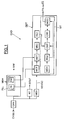
- the reference CVBS designates a video signal analog interleaving from a video source.
- the CVD video circuit which receives the CVBS analog signal, and which can for example be produced in the form of an integrated circuit on a silicon wafer, on the one hand comprises means for horizontal synchronization MSH, which can be of structure and operation known per se. More specifically, these means of horizontal synchronization include a loop PLL phase locked digital output signal SRF reference from an OSC controllable loop oscillator. As is conventional in the matter, this SRF reference signal is the output signal of the horizontal synchronization means MSH, and goes be synchronized with the video signal. In other words, after synchronization and in steady state, the transitions of the SRF signal correspond to horizontal synchronization pulses contained in the video signal.
- the SRF signal is also looped back to the comparator of PLL loop phase.
- the OSC oscillator is controlled, via the filter FB loop (for example of the integral proportional type), by a error signal representative of the phase difference between the video signal CVBS digitized and SRF signal.
- the sampling frequency applied in the means of horizontal synchronization MSH is for example of the order of 27 Mhz corresponding to a sampling clock whose edges amounts are spaced 37 nanoseconds apart.
- the OSC oscillator is then, for example, a cyclic counter incremented at the rate of the signal sampling clock and whose final count value nominal is for example equal to 1727, which corresponds to a video line length of 64 microseconds.
- the value final counting of this cyclic counter can vary around the nominal value so that synchronization on the CVBS video signal.
- the CVD video circuit includes DDT detection means, suitable for detecting the parity of the successive frames of the video signal.
- DDT means which will be discussed in more detail below on structure and function, in particular receive a VSYNC signal representative of the occurrence of a synchronization pulse vertical.
- This VSYNC signal is emitted by means of vertical synchronization MSV of conventional structure and known per se.
- MSV means receive the CVBS video signal digitized after passage in an analogical digital converter CAN.
- the reference SOUT designates the video signal digitized and delayed by a delay corresponding to a video line after passing through RT delay means. This allows to take into account for the delay in developing the VSYNC signal and making coincide with the elaborated parity indication, with the video output SOUT.
- FIG. 2 We will now also refer to FIG. 2 for describe the structure and operation of the detection means DDT.
- an LV video line located for example in the middle of the frame, begins with a horizontal synchronization pulse (synchronization top horizontal) TSH.
- This TSH pulse extends for example over 4.7 microseconds and at a level that is lower than the SE black level.
- the CVBS signal comprises a series of video lines forming a pre-equalization.
- the impulses of these lines video are shorter and more numerous than TSH pulses.
- the CVBS signal comprises several LVV video lines indicating the change of frame. Specifically, each line LVV has two pulses extending respectively over approximately 30 microseconds. The detection of these LVV video lines will allow the vertical synchronization means MSV to deliver the signal VSYNC.
- MCT accounting means will be triggered (step 20, figure 2).
- These MCT accounting means will record a predetermined number n of video lines, for example 16 video lines.
- these MCT accounting means can have a counter incremented to the rhythm of the clock signal sampling.
- the end of accounting signal is issued when the counter reaches a count value corresponding to the product of the number n by the average duration of a video line, duration which is for example contained in the loop filter FB of the loop to PLL digital phase lock.
- MDT determination means When the counter has delivered its end of count signal, MDT determination means will then determine the value of the horizontal phase of the video signal. To do so, MDT means will examine the value of the cyclic counter forming the oscillator of OSC loop to determine if the horizontal phase is between 1/4 and 3/4 or in the other half. More specifically, in this case, the MDT means will examine whether the value of the counter forming the OSC oscillator is between 0 and 1/4 of the counting limit or between 3/4 of the counting limit and the counting limit on the one hand, or between 1/4 of the counting limit and 3/4 of the counting limit counting on the other hand.
- means of update MMJ will update the value of a parity bit F contained in a first register RG1.
- FIG. 3 we will now refer more particularly to FIG. 3 to describe an embodiment of the method according to the invention allowing delivery by MT processing means (FIG. 1), an indication of the parity of the current frame.
- this indication of the parity of the current frame is the current value of an arbitrary parity bit FA or else the complemented current value FA of this arbitrary parity bit.
- control means MCD will deliver either the arbitrary parity bit FA (step 32) or the parity bit FA (step 31) as a function of the sign of the content of a CTP parity counter.
- the parity bit FA is delivered. While if the counter sign is negative it is the complemented bit FA that is issued.
- MCH means will modify (step 33) the value of the arbitrary parity bit FA contained in a second register RG2, and this for each occurrence of a new frame, that is to say at each occurrence of the signal VSYNC.
- CMP comparison means will then compare (step 35) the value of the arbitrary parity bit FA contained in the second register RG2 with the value of the parity bit F contained in the register RG1 and corresponding to the previous frame. If the two parity bits FA and F are identical (step 36) the control means MCD will increment the CTP parity counter (step 38).
- control means will decrement the CTP counter (step 37).
- the first register RG1 is updated (step 34) after n video lines, as shown above. At that time, the first register RG1 contains the value of the parity bit F associated with the frame current and which will be used for comparison with the parity bit FA during the next frame.
- the parity which is then sent in the digital stream at the output of the DDT device is no longer the detected parity but either the arbitrary parity FA (if the counter is positive) or the reverse FA of this arbitrary parity (if the counter is negative), this arbitrary parity being more reliable than the detected parity.
- the invention is compatible with synchronization horizontal such as that described in the French patent application n ° 01 13905.
- the detection of each horizontal synchronization pulse has a video signal sampling, low-pass signal filtering sampled SN, a thresholding of the filtered signal SNF so as not to leave only pulses whose level is less than one threshold, and a selection according to a selection criterion predetermined, among the residual pulses located inside an observation window centered on a signal transition reference, of that (IMPS) which corresponds to said pulse of horizontal synchronization.
- one analyzes all the tops generated after thresholding and we classify them according to their likelihood level.
- the top with the maximum of likelihood is then selected to update the order of the loop oscillator.
- the selection criterion can include, for example, a criterion of dimension compared to an average dimension (average width) of a horizontal synchronization pulse.
- the selection criterion may include a position criterion relative to the expected position of the synchronization pulse horizontal.
- the expected position of the horizontal synchronization pulse is that of the transition from reference signal.
- the selection criterion can combine the two criteria previously mentioned, i.e. the position criterion and the sizing criteria.
- the weighting can change depending on the applications for adapt in particular to the different types of video source as well as to the quality of this video signal.
- the video source is for example a video recorder, which most likely leads to a phase jump at the end of the frame, we will then promote the width of the synchronization pulses relative to their position.
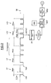
- CVD video circuit according to the invention can include on the same silicon chip, the means of MSH horizontal synchronization illustrated in Figure 4.
- the analog-to-digital ADC converter is tracked an LPF low pass filter.
- the cutoff frequency of this low pass filter is typically between 200 kHz and 2 MHz, and preferably between 500 kHz and 1 MHz. Such a filter allows to eliminate a good part of the noise and of the sub-carrier of chrominance.
- the filtered SNF sampled signal is then delivered to MSE thresholding means. These carry out a thresholding of the signal of so as to eliminate any part of the SNF signal whose level is above of a threshold.
- This threshold is for example of the order of 50% of the average amplitude measured from a horizontal synchronization top.
- the digital signal SNS therefore includes residual pulses which are considered to be potential horizontal synchronization pulses.
- MSL selection means will then select a IMPS pulse which will be considered as the pulse of horizontal synchronization.
- This IMPS pulse will then be delivered to the PLL phase locked loop comprising the CMPH phase comparator followed by the FB loop filter and the controllable oscillator OSC delivering the reference signal SRF.
- This SRF signal is also looped back to the comparator of CMPH phase and also on the selection means in order to allow selection according to a predetermined criterion.
- the oscillator is therefore controlled via the loop filter FB, by the error signal ERR representative of the deviation phase between the selected IMPS pulse and a transition from SRF signal.
Landscapes
- Engineering & Computer Science (AREA)
- Multimedia (AREA)
- Signal Processing (AREA)
- Synchronizing For Television (AREA)
- Television Systems (AREA)
Applications Claiming Priority (2)
| Application Number | Priority Date | Filing Date | Title |
|---|---|---|---|
| FR0114058 | 2001-10-30 | ||
| FR0114058A FR2831755A1 (fr) | 2001-10-30 | 2001-10-30 | Procede et dispositif de detection de la parite des trames successives d'un signal video entrelace |
Publications (2)
| Publication Number | Publication Date |
|---|---|
| EP1309183A2 true EP1309183A2 (de) | 2003-05-07 |
| EP1309183A3 EP1309183A3 (de) | 2004-02-04 |
Family
ID=8868901
Family Applications (1)
| Application Number | Title | Priority Date | Filing Date |
|---|---|---|---|
| EP02292647A Ceased EP1309183A3 (de) | 2001-10-30 | 2002-10-24 | Verfahren und Vorrichtung zur Detektion der Parität von aufeinandervolgenden Halbbildern eines Zeilensprungvideosignals |
Country Status (3)
| Country | Link |
|---|---|
| US (1) | US7023489B2 (de) |
| EP (1) | EP1309183A3 (de) |
| FR (1) | FR2831755A1 (de) |
Families Citing this family (2)
| Publication number | Priority date | Publication date | Assignee | Title |
|---|---|---|---|---|
| US7701512B1 (en) * | 2003-05-20 | 2010-04-20 | Pixelworks, Inc. | System and method for improved horizontal and vertical sync pulse detection and processing |
| EP1681878A1 (de) * | 2005-01-12 | 2006-07-19 | Thomson Licensing | Zeitbasiskorrekturschaltung für ein Digitalvideosignal |
Family Cites Families (13)
| Publication number | Priority date | Publication date | Assignee | Title |
|---|---|---|---|---|
| US4553185A (en) * | 1968-03-18 | 1985-11-12 | Ampex Corporation | Method and apparatus for recording and reproducing television or other broad band signals with an altered time base effect |
| US4575770A (en) * | 1983-12-05 | 1986-03-11 | Rca Corporation | Video disc data systems for interactive applications |
| DE3443925C1 (de) * | 1984-12-01 | 1986-01-30 | Philips Patentverwaltung Gmbh, 2000 Hamburg | Schaltungsanordnung zum Unterscheiden der beiden Halbbilder in einem Fernsehsignal |
| US4827341A (en) * | 1986-12-16 | 1989-05-02 | Fuji Photo Equipment Co., Ltd. | Synchronizing signal generating circuit |
| EP0309610B1 (de) * | 1987-10-02 | 1993-01-07 | Deutsche ITT Industries GmbH | Digitale Erzeugung von Vertikalsynchron- und Halbbild-Identifikationssignalen |
| DE3905669C2 (de) * | 1989-02-24 | 1996-03-07 | Broadcast Television Syst | Schaltungsanordnung zur Ableitung von Synchronsignalen aus einem digitalen Videosignal |
| US5025496A (en) * | 1990-05-07 | 1991-06-18 | Rca Licensing Corporation | Odd/even field detector for video signals |
| JP2746741B2 (ja) * | 1990-09-28 | 1998-05-06 | シャープ株式会社 | フィールド決定回路 |
| KR950005054B1 (ko) * | 1991-12-31 | 1995-05-17 | 삼성전자주식회사 | 기수/우수의 필드 검출장치 |
| US5619275A (en) * | 1992-09-01 | 1997-04-08 | Thomson Consumer Electronics, Inc. | TV line and field detection apparatus with good noise immunity |
| JPH06245098A (ja) * | 1993-02-16 | 1994-09-02 | Sharp Corp | フィールド決定回路 |
| KR0170730B1 (ko) * | 1996-01-12 | 1999-03-20 | 김광호 | 필드 동기신호 검출회로 및 그 방법 |
| KR100219626B1 (ko) * | 1997-01-31 | 1999-09-01 | 윤종용 | 필드 판별신호 발생회로 및 그 방법 |
-
2001
- 2001-10-30 FR FR0114058A patent/FR2831755A1/fr active Pending
-
2002
- 2002-10-24 EP EP02292647A patent/EP1309183A3/de not_active Ceased
- 2002-10-29 US US10/283,029 patent/US7023489B2/en not_active Expired - Fee Related
Also Published As
| Publication number | Publication date |
|---|---|
| US7023489B2 (en) | 2006-04-04 |
| FR2831755A1 (fr) | 2003-05-02 |
| EP1309183A3 (de) | 2004-02-04 |
| US20030081148A1 (en) | 2003-05-01 |
Similar Documents
| Publication | Publication Date | Title |
|---|---|---|
| EP0421897B1 (de) | Vorrichtung zum Extrahieren von digitalen Daten aus einem Video-Signal | |
| EP0702862B1 (de) | Verfahren zur verbesserung der rauschunempfindlichkeit eines phasenregelkreises und einrichtung, die ein solches verfahren verwendet | |
| EP1868383A1 (de) | Bewegungsphasendetektion einer Videohalbbildersequenz | |
| EP0159924A1 (de) | Digitaler "DIDON"-Demodulator | |
| FR2482814A1 (fr) | Procede et dispositif pour coder et decoder des signaux video par inversion repetitive de la polarite de ces signaux | |
| EP0459911B1 (de) | Verfahren zum Vermindern von Niederfrequenz-Zitterkomponenten in einem digitalen Daten-Übertragungssystem | |
| EP0282106B1 (de) | System zur Synchronisierung auf einem halbdigitalen Signal | |
| EP0115234A1 (de) | Verfahren und Schaltung zur Frequenz- und Phasenverkopplung eines örtlichen Oszillators im Fernsehen | |
| EP0323935B1 (de) | Schaltung zur Erkennung eines Videorecordersignals | |
| EP0029780A1 (de) | Anlage zum Prüfen eines Fernseh-Videotext-Empfängers | |
| FR2514221A1 (fr) | Circuit de synchronisation servant a deduire et a traiter un signal de synchronisation present dans un signal video incident | |
| EP1309183A2 (de) | Verfahren und Vorrichtung zur Detektion der Parität von aufeinandervolgenden Halbbildern eines Zeilensprungvideosignals | |
| EP0732845B1 (de) | Verfahren und Vorrichtung zur Synchronisierung eines digitalen Videosignals | |
| EP1309184A1 (de) | Verfahren und Vorrichtung zum Synchronisierung eines Referenzsignales mit einem Videosignal | |
| FR2515462A1 (fr) | Tourne-videodisque ayant un generateur perfectionne de signaux de temporisation verticale | |
| EP0594512B1 (de) | Schaltung zur Erkennung von Fernsehstandards | |
| EP0415494B1 (de) | Verfahren und Vorrichtung zur Bildverarbeitung von verbesserter Bewegungseinschätzung | |
| EP0148098A2 (de) | Schaltung zur Regeneration von periodischen Signalen | |
| FR2538196A1 (fr) | Appareil et procede de lecture de code numerique | |
| EP0905946A1 (de) | Reglung der Abtastung von Biphasensignale | |
| FR2859329A1 (fr) | Procede et dispositif de traitement du decalage frequentiel de la frequence porteuse d'un signal module avec une modulation monoporteuse continue en quadrature | |
| EP1964272B1 (de) | Synchrone digitaldatenübertragungsschnittstelle | |
| FR2920942A1 (fr) | Synchronisation d'equipements independante du standard du signal de synchronisation | |
| FR2832281A1 (fr) | Procede et dispositif de commande du fonctionnement d'un circuit de synchronisation video, en particulier pour la detection de la nature de la source video, par exemple un magnetoscope | |
| FR2856873A1 (fr) | Systeme de reception d'un signal video |
Legal Events
| Date | Code | Title | Description |
|---|---|---|---|
| PUAI | Public reference made under article 153(3) epc to a published international application that has entered the european phase |
Free format text: ORIGINAL CODE: 0009012 |
|
| AK | Designated contracting states |
Designated state(s): AT BE BG CH CY CZ DE DK EE ES FI FR GB GR IE IT LI LU MC NL PT SE SK TR |
|
| AX | Request for extension of the european patent |
Extension state: AL LT LV MK RO SI |
|
| PUAL | Search report despatched |
Free format text: ORIGINAL CODE: 0009013 |
|
| AK | Designated contracting states |
Kind code of ref document: A3 Designated state(s): AT BE BG CH CY CZ DE DK EE ES FI FR GB GR IE IT LI LU MC NL PT SE SK TR |
|
| AX | Request for extension of the european patent |
Extension state: AL LT LV MK RO SI |
|
| 17P | Request for examination filed |
Effective date: 20040713 |
|
| AKX | Designation fees paid |
Designated state(s): DE FR GB IT |
|
| 17Q | First examination report despatched |
Effective date: 20050118 |
|
| STAA | Information on the status of an ep patent application or granted ep patent |
Free format text: STATUS: THE APPLICATION HAS BEEN REFUSED |
|
| 18R | Application refused |
Effective date: 20080307 |