EP1309501B1 - Container pour le transport de feuilles de verre - Google Patents
Container pour le transport de feuilles de verre Download PDFInfo
- Publication number
- EP1309501B1 EP1309501B1 EP01969577A EP01969577A EP1309501B1 EP 1309501 B1 EP1309501 B1 EP 1309501B1 EP 01969577 A EP01969577 A EP 01969577A EP 01969577 A EP01969577 A EP 01969577A EP 1309501 B1 EP1309501 B1 EP 1309501B1
- Authority
- EP
- European Patent Office
- Prior art keywords
- sheets
- bar
- strap
- container
- backrest
- Prior art date
- Legal status (The legal status is an assumption and is not a legal conclusion. Google has not performed a legal analysis and makes no representation as to the accuracy of the status listed.)
- Expired - Lifetime
Links
- 239000011521 glass Substances 0.000 title claims abstract description 27
- 230000000903 blocking effect Effects 0.000 abstract description 2
- 230000006641 stabilisation Effects 0.000 abstract description 2
- 125000006850 spacer group Chemical group 0.000 description 15
- 238000007373 indentation Methods 0.000 description 4
- 239000000463 material Substances 0.000 description 4
- 238000000034 method Methods 0.000 description 4
- 238000012423 maintenance Methods 0.000 description 3
- 229920002994 synthetic fiber Polymers 0.000 description 3
- 230000000712 assembly Effects 0.000 description 2
- 238000000429 assembly Methods 0.000 description 2
- 238000010276 construction Methods 0.000 description 2
- 230000000284 resting effect Effects 0.000 description 2
- 230000035939 shock Effects 0.000 description 2
- 239000002699 waste material Substances 0.000 description 2
- 239000004743 Polypropylene Substances 0.000 description 1
- 239000004793 Polystyrene Substances 0.000 description 1
- 241001639412 Verres Species 0.000 description 1
- 238000005299 abrasion Methods 0.000 description 1
- 230000006978 adaptation Effects 0.000 description 1
- 230000033228 biological regulation Effects 0.000 description 1
- 238000006243 chemical reaction Methods 0.000 description 1
- 230000006835 compression Effects 0.000 description 1
- 238000007906 compression Methods 0.000 description 1
- 239000005356 container glass Substances 0.000 description 1
- 238000006073 displacement reaction Methods 0.000 description 1
- 239000004794 expanded polystyrene Substances 0.000 description 1
- 230000033001 locomotion Effects 0.000 description 1
- 230000014759 maintenance of location Effects 0.000 description 1
- 239000002184 metal Substances 0.000 description 1
- 238000012986 modification Methods 0.000 description 1
- 230000004048 modification Effects 0.000 description 1
- 238000004806 packaging method and process Methods 0.000 description 1
- -1 polypropylene Polymers 0.000 description 1
- 229920001155 polypropylene Polymers 0.000 description 1
- 229920002223 polystyrene Polymers 0.000 description 1
- 238000004321 preservation Methods 0.000 description 1
- 238000011160 research Methods 0.000 description 1
- 238000011105 stabilization Methods 0.000 description 1
- 230000009897 systematic effect Effects 0.000 description 1
- 230000029305 taxis Effects 0.000 description 1
- 238000012546 transfer Methods 0.000 description 1
- 238000013519 translation Methods 0.000 description 1
Images


Classifications
-
- B—PERFORMING OPERATIONS; TRANSPORTING
- B65—CONVEYING; PACKING; STORING; HANDLING THIN OR FILAMENTARY MATERIAL
- B65D—CONTAINERS FOR STORAGE OR TRANSPORT OF ARTICLES OR MATERIALS, e.g. BAGS, BARRELS, BOTTLES, BOXES, CANS, CARTONS, CRATES, DRUMS, JARS, TANKS, HOPPERS, FORWARDING CONTAINERS; ACCESSORIES, CLOSURES, OR FITTINGS THEREFOR; PACKAGING ELEMENTS; PACKAGES
- B65D85/00—Containers, packaging elements or packages, specially adapted for particular articles or materials
- B65D85/30—Containers, packaging elements or packages, specially adapted for particular articles or materials for articles particularly sensitive to damage by shock or pressure
- B65D85/48—Containers, packaging elements or packages, specially adapted for particular articles or materials for articles particularly sensitive to damage by shock or pressure for glass sheets
-
- Y—GENERAL TAGGING OF NEW TECHNOLOGICAL DEVELOPMENTS; GENERAL TAGGING OF CROSS-SECTIONAL TECHNOLOGIES SPANNING OVER SEVERAL SECTIONS OF THE IPC; TECHNICAL SUBJECTS COVERED BY FORMER USPC CROSS-REFERENCE ART COLLECTIONS [XRACs] AND DIGESTS
- Y02—TECHNOLOGIES OR APPLICATIONS FOR MITIGATION OR ADAPTATION AGAINST CLIMATE CHANGE
- Y02W—CLIMATE CHANGE MITIGATION TECHNOLOGIES RELATED TO WASTEWATER TREATMENT OR WASTE MANAGEMENT
- Y02W30/00—Technologies for solid waste management
- Y02W30/50—Reuse, recycling or recovery technologies
- Y02W30/80—Packaging reuse or recycling, e.g. of multilayer packaging
Definitions
- the present invention relates to containers used for transport and storage of glass sheets.
- the sheets must be held firmly so that the lots formed remain stable during handling and shocks related to transport.
- the sheets are arranged substantially vertical on rack elements, which keep them separate from each other others at their bottom.
- These assemblies also include systems in position, which must necessarily be adjustable to adapt to a certain diversity of shapes and dimensions, the same systems of transport that can be used for different glazing. Given the use of these containers, it is indeed necessary to be able to use them for products that are periodically changed, and / or a wide variety of products.
- the containers usually include moving parts which are held tight against the glass sheets by means of elements of type "straps", also called “straps".
- traps also called “straps”.
- the inventors therefore aimed to offer containers for transporting glass sheets which no longer require the use of non-glass products reusable, or at least limit the use of such products as much as possible, while retaining the capacity of these containers to easily receive products from various shapes and sizes.
- the inventors tried to remove all wedges usually made of blocks of more or less compressible material, such as that expanded synthetic materials, especially polystyrenes very widely used for all packaging uses.
- the inventors have developed means of fixing batches of glass sheets which allow simple and inexpensive adaptation to differences in shape and volume of batches arranged in containers.
- a container of the type comprising means for fixing comprising at least one bar held against the batch of sheets by the tension of a strap (or strap), and by the strap itself, the distance between the backrest and the point of passage of the strap on the bar is adjustable along the bar to match the size of the lot placed on the container.
- the adjustment of the strap crossing point distance is by example obtained using a telescopic bar.
- the waypoint is in this case arranged at the end of the bar. It is the deployment of the telescopic bar which allows you to adjust the bar to the length best suited to the dimensions of the batch of leaves.
- This embodiment of the invention does indeed achieve the goal research. However, it requires a complete modification of the bars used at the current time. For this reason the inventors have also proposed an implementation work which makes it possible to preserve the existing bars. In this second type of embodiment, the length of the bar remains unchanged, and the waypoint is adjustable along the length of this bar.
- the structure of used straps are modified so that a significant part of them remains in permanently attached to the container structure.
- the invention also proposes that the strap used for blocking the glass sheets is only placed on the part of the bar attachment which is furthest from the container folder.
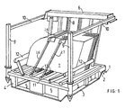
- Figure 1 shows schematically a transport container glass sheets.
- the container of Figure 1 comprises a base, or floor, of form substantially rectangular.
- This floor is formed by two frames, upper 2 and lower 3, made up of beams.
- the two frames are fixed to each other by spacer elements 4 arranged at the corners of the frames and in the middle of the sides.
- the geometry of the base 1 is such that it releases openings 5 allowing riding on a forklift.
- Uprights 9, and crosspieces high 10 complete the definition of the volume of this container. Glass sheets stacked rest on the crosspieces 11 fixed to the frame of the floor. In the example presented the glass sheets are automobile side windows.
- the same types containers are used for windshields or any other sheet of glass.
- lateral locking elements are also shown in the form of two bars 12, whose position is adjustable to adapt to the shape and dimensions stacked leaves.
- the glass sheets In the traditional mode represented, the glass sheets, on their side resting on the floor, are engaged in the indentations of the racks 13 arranged on two crosspieces 11. In the upper part the leaves are usually separated by spacers formed, for example, by jumpers 17 placed on the leaves themselves.
- the crosspieces 11 and the racks 13 are produced in materials such that on contact, the glass sheets are not likely to be damaged. These are for example metal profiles coated with a strip of rigid synthetic material.
- brelage bars 14 and 15 Maintaining the leaves at the top is obtained by by means of so-called brelage bars 14 and 15. These bars are engaged in the uprights 8, which are part of the file, slidingly to allow their height positioning corresponding to the dimensions of the stack of sheets concerned.
- the bars 14 and 15 rest on the jumpers / spacers arranged in line on the upper edge of the leaves. In this way there is no direct contact of bars 14 and 15 with the leaves. Spacers, which are made of synthetic material resilient, maintain, without risk of damaging the leaves.
- Straps 16 and 17 are stretched over bars 14 and 15, which they keep firmly applied to the top of the stack of sheets. These straps are rigid enough to, when tightened, not loosen under the vibrations or other mechanical stresses specific to this type of use. Straps of this type are well known, and for example consist of strips of reinforced polypropylene.
- the timing elements have been omitted glass sheets on the front of the stack. These wedging elements are made necessary when the bars exceed the depth of the stack.
- the shims is practically systematic taking into account the fact that the length of bars 14 and 15 not being adjustable, it does not generally correspond not to the depth of the stack.
- the pressure on the top of the stacking is usually insufficient to keep the sheets in the direction of depth, and the straps are not in contact with the front face of the stack.
- FIG. 2 shows schematically the assembly method prior.
- this figure shows the location of the strap 16, and its commitment to the different elements of the assembly made up.
- the glass sheets provided with jumpers 17, are engaged in the indentations of the rack 13 carried by the cross member 11.
- the backrest upright 8 is slightly inclined relative to the vertical, which allows to transfer a significant part of the forces exerted in a horizontal direction, on the amount 8, and consequently limits the necessary support on the front face of stacking.
- the jumper carried by the sheet closest to the back rests on the upright 8, and prevents direct contact with the glass sheet, contact which would scratch and abrasion generator. Likewise, the riders in contact with each other others fulfill the same function with respect to the leaves between them.
- the braching bar 14 is held in position on the jumpers, on the one hand by the sliding engagement of its end in the upright 8, and on the other part, by the pressure exerted by the strap 16.
- the latter forms a loop.
- She passes successively on the rods fixed respectively on the bar 14 (18, 19), on the backrest upright 8 (20), and on a ring 21 arranged at the end of the cross-member 11.
- These are for example round rods which allow the strap to slide freely, so that it is held in position, and well stretched over its entire length.
- the strap is traditionally stretched and welded on itself as shown in 22.
- the lashing bar 14 greatly exceeds the depth of stacking of leaves.
- the two strands of the strap 16 located on the front of the container are then at a distance from the sheets and cannot participate in the keeping them in position.
- the interposition of a wedge 23 of thickness slightly greater than the distance between the front face of the stack and the strap, comes compensate for the absence of direct maintenance.
- the wedge is necessarily placed opposite the upper part of stacking. Apart from the inconvenience for the recipient of having these materials constituting non-recycled products, the use of a shim is not fully satisfactory. Maintaining its position is not perfectly guaranteed. It is only ensured by the pressure exerted by the strap. Shocks or vibrations during handling or transport can cause displacement of the wedge. This may even lead to the release of the wedge and therefore a loss of stability of the stack.
- the embodiment corresponding to the invention shown in FIG. 3 makes it possible to resolve these difficulties, by obtaining the stabilization of stacking in the depth direction by means of the strap itself, which is stable in position and in tension. Furthermore, this embodiment eliminates the use of wedges.
- the strap 16 passes through an element 24, such as a ring, element movable in translation on the lashing bar 14.
- the strap still passes as above on the rods 18, 19, 20 and the ring 21. It possibly passes over a rod fixed under the bar of wire 14 on the side of the backrest amount 8. The latter avoids any traction important on the rider in contact with the upright 8. This rod may not be necessary.
- the strap can rest directly on the last rider.
- FIG. 4 shows in detail the bar 14 carrying the movable element 24.
- a ring 24 of generally rectangular shape, and of circular section is engaged on bar 14.
- the dimensions of this ring are slightly larger to those of the section of the bar 14 so that the ring 24 can slide freely and without excessive lateral play.
- the strap 16 above the bar 14 is supported on the ring 24 and the plate on the bar. It passes over the rod 18 and descends towards the rod 21 fixed on the cross member 11. It then rises to pass through the ring 24.
- the tension of the strap presses the lower side 26 of the ring on the spacer 17.
- the presence of the ring 24 allows the strap to be held under the bar 14. Direct passage of the latter on the stirrup 17 would not guarantee a proper positioning.
- the strap was applied directly to the spacer 17, the effort would be exerted essentially in a vertical direction.
- the horizontal component would be limited.
- the lower side 26 of ring 24 transforms part of the vertical component into horizontal component, favoring the desired maintenance.
- the end of the bar located on the side of the backrest has a slide 19a, which superimposed on the rod 19. This slide constituted by a cylindrical wall attached to the end of the bar 14 improves the sliding of the strap when it is tightened.
- Figure 5 shows the relative position of the ring 24, the bar 14 and the spacer 17, corresponding to the configuration in FIG. 4.
- the part 26 of the ring 24 is wider than that corresponding to the width necessary to slide on the bar 14.
- the extension of the part 26 allows a better distribution of the pressure exerted on the top of the spacer 17.
- the section of the part 26 is also advantageously more important to promote the horizontal component of the reaction on the spacer, as it was indicated above.
- FIGS. 4 and 5 it can also be seen that the part 26 of the ring 24 rests on the part of the spacer 17 located above the sheet of glass that carries this spacer. In this provision, the compression exerted on this part of the spacer cannot damage the glass sheet.
- the drawing of the spacer also shows in FIG. 5, the existence of a groove at its upper part.
- This groove 27 is of sufficient width so that the bar 14 can be inserted. In this way the spacers remain suitably aligned with each other. This alignment is the necessary condition so that the distances between the sheets are well preserved.
- Figure 5 again shows the location of the strap relative to the other elements.
- the upper strand is arranged above the bar 14.
- the strand lower pass in the groove 27, under the bar 14.
- the end of the bar 14 carries a sleeve 28 ,. in which the strap passes in the direction of the cross member 11 and the ring 21.
- the sleeve is integral with the bar 14.
- the sleeve 28 protects the strap against pinching and accidental tears in the strap which could result, at the locations where this strap is most exposed.
- the lashing bar 14 is held against the upper part of the stack by the tension of the passing strap on the one hand in the ring 21 and on the other hand on the rod 20 secured to the upright 8.
- the amount 8 can have several rods of the same type arranged at a distance from each other on the height of the upright 8. To limit the length of the strap used, we then choose the rod closest to the bar 14 located at below the latter.
- Attaching the strap to the upright 8 requires the use of a relatively long strap.
- the invention also alternatively proposes to replace the single strap which is placed discarded after use, by a two-part strap. Based on the finding that the length of the strap varies to a limited extent, whatever the dimensions of the proposed stack of sheets, the inventors propose to leave a loop of the minimum length necessary to fit practically all stacks, and to associate an adjustment loop, which is only discarded after use.
- Figure 6 illustrates this particular form.
- the overall construction is of the same type as for the example previous.
- the strap 16 forms a loop whose end on the front face carries a junction ring 33.
- This strap is of such dimensions as for larger stacks, ring 33 is raised until it comes close to the chute 28.
- the end of the strap descends further along the face of the stack. Tightening takes place with a second strap element 34, which passes through the ring 33 and, as previously in ring 21.
- FIG 7. Another example of construction according to the invention, making it possible to reduce the volume of the straps used is shown in figure 7.
- the strap passes only over the tying bar 14, the adjustable element 24, and the ring 21 fixed to the cross member 11. This avoids fixing to the backrest upright 8.
- the strap is passed over the rods 29 and 30, fixed on the bar 14.
- openings are practiced opposite rods 29 and 30 in the lower and upper walls of the bar 14.
- the width of the strap, and that of the bar 14, are chosen to so that the strap can pass through the opening without deformation.
- the location of rods 29 and 30 and the corresponding openings on the bar 14 is chosen to allow the positioning of the ring 24, in the configurations corresponding to the shallowest stacks encountered in the convenient.
- the bar In all assemblies of bars 14 and straps 16, the bar must be held firmly over the entire depth of the stack. He is in particular necessary that the bar 14 maintains its support on the spacers arranged on all sheets, including those close to the file.
- FIG. 8 shows the method of fixing the bar 14 to the upright 8.
- a log 31 slides in the upright 8 resting on the two side walls of the two U- shaped profiles constituting the upright 8.
- Elements 35 fixed to the log 31 limit the longitudinal play of the bar 14 after it has been set to the appropriate height.
- the strap 16 passes over the log 31 and then into the upright 8 to go to a rod 32 secured to the upright 8 and then goes back up to come on the jumper 17.
- Element 37 movable in height in the profile 36, extends over the entire length of the bar 14
- the element 37 is pushed back towards the stirrups 17 by the set of springs 38 housed in the closed off.
- the movement of the element 37 in the profile 36 is sufficient to cover the distance separating two positions corresponding to two successive indentations of the folder.
Landscapes
- Engineering & Computer Science (AREA)
- Mechanical Engineering (AREA)
- Packaging Frangible Articles (AREA)
- Buffer Packaging (AREA)
- Packaging Of Annular Or Rod-Shaped Articles, Wearing Apparel, Cassettes, Or The Like (AREA)
- Glass Compositions (AREA)
- Re-Forming, After-Treatment, Cutting And Transporting Of Glass Products (AREA)
Description
- la figure 1 est une vue schématique en perspective d'un container de transport de feuilles de verre;
- la figure 2 est une vue schématique de côté, présentant l'emplacement de la sangle dans le mode traditionnel;
- la figure 3 est analogue à la précédente pour un mode réalisation selon l'invention;
- la figure 4 présente un détail agrandi, de la barre de brelage de la figure 3 ;
- la figure 5 montre en vue de face les dispositions respectives de certains éléments mis en oeuvre selon l'invention;
- la figure 6 analogue aux figures 2 et 3, présente un mode de réalisation avec sangle "courte";
- la figure 7 présente un autre mode de réalisation du type de celui de la figure 6;
- la figure 8 présente un détail du mode de fixation de la sangle sur le dossier du container;
- la figure 9 présente un mode de réalisation de barre de brelage dont la hauteur est variable.
Claims (8)
- Container pour le transport et le stockage de lots de feuilles de verre (7) comprenant un plancher muni de moyens (13) de séparation des feuilles, un dossier sensiblement vertical, ou légèrement incliné, des moyens de blocage latéral (12) adaptables aux dimensions latérales des feuilles, et des barres de brelage (14, 15) disposées à la partie supérieure du lot de feuilles, une extrémité de ces barres étant engagée de manière coulissante dans des montants (8) constituant le dossier du container, lesdites barres de brelage étant plaquées contre le lot de feuilles par des sangles (16, 17) passant sur des points d'attache (20, 21) solidaires de la structure du container, caractérisé en ce que les sangles passent sur les barres de brelage, et en ce que pour maintenir le lot de feuilles dans la profondeur du container, la distance entre le dossier et le point de passage de chaque sangle sur chaque barre de brelage, du côté opposé au dossier, est réglable pour s'ajuster à la profondeur du lot de feuilles.
- Container selon la revendication 1, dans lequel la distance entre le dossier et le point de passage de la sangle sur la barre de brelage est réglé par le jeu d'un assemblage télescopique de la barre.
- Container selon la revendication 1, dans lequel la position du point de passage de la sangle sur la barre est réglée par coulissement d'un anneau (24) sur la barre, anneau dans lequel passe la sangle.
- Container selon la revendication 3, dans lequel les feuilles de verre étant espacées les unes des autres à leur partie supérieure par des cavaliers (17) alignés sous la barre de brelage, l'anneau coulissant sur la barre est pressé contre le cavalier de la feuille de verre la plus distante du dossier, par tension de la sangle.
- Container selon la revendication 4, dans lequel la forme et les dimensions de l'anneau sont choisies pour qu'il s'appuie sur la partie du cavalier située au dessus de la feuille de verre.
- Container selon l'une des revendications précédentes, dans lequel la sangle se compose de deux éléments constituant deux boucles réunies par un anneau (33) une boucle étant fixée au dossier et s'étendant au moins le long de la barre de brelage, l'autre boucle (34) s'étendant sur une partie au moins de la hauteur du lot de feuilles depuis le point de fixation (21) au socle.
- Container selon la revendication 6, dans lequel la boucle de sangle fixée au dossier reste solidaire du container, et est réutilisée avec lui, seule la seconde boucle de sangle étant rompue pour retirer les feuilles du container.
- Container selon l'une des revendications 1 à 5 dans lequel la sangle maintenant la barre de brelage contre le lot de feuilles de verre, s'étend seulement sur une partie de la longueur de la barre, longueur correspondant à l'amplitude maximum des variations de profondeur des lots de feuilles de verre, le maintien de la barre à son extrémité coopérant avec le dossier étant obtenu par des moyens solidaires du dossier assurant une série de positions prédéterminées à distance limitée les unes des autres, les positions intermédiaires étant assurées par modulation de la hauteur de la barre de brelage.
Applications Claiming Priority (3)
| Application Number | Priority Date | Filing Date | Title |
|---|---|---|---|
| BE2000/0499A BE1013640A6 (fr) | 2000-08-08 | 2000-08-08 | Container pour le transport de feuilles de verre. |
| BE200000499 | 2000-08-08 | ||
| PCT/EP2001/009139 WO2002012091A1 (fr) | 2000-08-08 | 2001-08-06 | Container pour le transport de feuilles de verre |
Publications (2)
| Publication Number | Publication Date |
|---|---|
| EP1309501A1 EP1309501A1 (fr) | 2003-05-14 |
| EP1309501B1 true EP1309501B1 (fr) | 2004-10-20 |
Family
ID=3896624
Family Applications (1)
| Application Number | Title | Priority Date | Filing Date |
|---|---|---|---|
| EP01969577A Expired - Lifetime EP1309501B1 (fr) | 2000-08-08 | 2001-08-06 | Container pour le transport de feuilles de verre |
Country Status (6)
| Country | Link |
|---|---|
| EP (1) | EP1309501B1 (fr) |
| AT (1) | ATE280105T1 (fr) |
| AU (1) | AU2001289790A1 (fr) |
| BE (1) | BE1013640A6 (fr) |
| DE (1) | DE60106628T2 (fr) |
| WO (1) | WO2002012091A1 (fr) |
Cited By (1)
| Publication number | Priority date | Publication date | Assignee | Title |
|---|---|---|---|---|
| DE202013011439U1 (de) | 2013-12-20 | 2014-02-04 | Schenker Cargo Oy | Transportvorrichtung für scheibenförmige Gegestände |
Families Citing this family (1)
| Publication number | Priority date | Publication date | Assignee | Title |
|---|---|---|---|---|
| WO2010060469A1 (fr) * | 2008-11-26 | 2010-06-03 | Agc Flat Glass Europe Sa | Conteneur pour le transport et/ou le stockage de feuilles d'un matériau rigide |
Family Cites Families (3)
| Publication number | Priority date | Publication date | Assignee | Title |
|---|---|---|---|---|
| DE167693C (fr) * | ||||
| DE1205898B (de) * | 1961-02-15 | 1965-11-25 | Detag | Transportvorrichtung fuer gebogene Glasscheiben |
| DE3843187C1 (fr) * | 1988-12-22 | 1990-06-13 | Vegla Vereinigte Glaswerke Gmbh, 5100 Aachen, De |
-
2000
- 2000-08-08 BE BE2000/0499A patent/BE1013640A6/fr not_active IP Right Cessation
-
2001
- 2001-08-06 AU AU2001289790A patent/AU2001289790A1/en not_active Abandoned
- 2001-08-06 AT AT01969577T patent/ATE280105T1/de not_active IP Right Cessation
- 2001-08-06 WO PCT/EP2001/009139 patent/WO2002012091A1/fr not_active Ceased
- 2001-08-06 DE DE2001606628 patent/DE60106628T2/de not_active Expired - Lifetime
- 2001-08-06 EP EP01969577A patent/EP1309501B1/fr not_active Expired - Lifetime
Cited By (1)
| Publication number | Priority date | Publication date | Assignee | Title |
|---|---|---|---|---|
| DE202013011439U1 (de) | 2013-12-20 | 2014-02-04 | Schenker Cargo Oy | Transportvorrichtung für scheibenförmige Gegestände |
Also Published As
| Publication number | Publication date |
|---|---|
| DE60106628D1 (de) | 2004-11-25 |
| ATE280105T1 (de) | 2004-11-15 |
| WO2002012091A1 (fr) | 2002-02-14 |
| EP1309501A1 (fr) | 2003-05-14 |
| BE1013640A6 (fr) | 2002-05-07 |
| DE60106628T2 (de) | 2005-11-10 |
| AU2001289790A1 (en) | 2002-02-18 |
Similar Documents
| Publication | Publication Date | Title |
|---|---|---|
| LU83495A1 (fr) | Dispositif de manutention d'articles en feuilles | |
| FR3032441A1 (fr) | Procede et systeme de dechargement de colis | |
| FR3021985A1 (fr) | Dispositif de raccordement a stabilite amelioree | |
| FR2711112A1 (fr) | Dispositif de positionnement de bobine et procédé d'emballage utilisant ce dispositif. | |
| FR2968290A1 (fr) | Unite de chargement et de transport de pieces et son application au chargement de pieces en tole embouties pour vehicules automobiles | |
| FR2503095A1 (fr) | Dispositif pour le conditionnement des articles de grande longueur, notamment des bandes transporteuses | |
| BE1013640A6 (fr) | Container pour le transport de feuilles de verre. | |
| FR2967982A1 (fr) | Moyens de maintien d'un chargement dans un contenant de transport | |
| FR2727671A1 (fr) | Boite articulee de transport de pieces detachees | |
| EP1955967B1 (fr) | Emballage pour des produits sensiblement parallélépipédiques | |
| EP0216690B1 (fr) | Dispositif de manutention d'articles en feuilles | |
| FR2548633A1 (fr) | Elements intercalaires destines a la manutention et a la separation d'articles en feuilles | |
| BE1016103A4 (fr) | Organe de ceinturage d'un paquet de feuilles rigides, dispositif pour la manutention de paquets de feuilles rigides et palette de feuilles rigides. | |
| EP0595744B1 (fr) | Palette démontable et gerbable, en particulier pour produits en feuilles | |
| EP0939018B1 (fr) | Dispositif de calage automatique de pièces cylindriques ou parallélépipédiques et wagon utilisant un tel dispositif | |
| WO2010060469A1 (fr) | Conteneur pour le transport et/ou le stockage de feuilles d'un matériau rigide | |
| BE1013176A3 (fr) | Conteneur pour le transport de feuilles de materiaux rigides. | |
| WO2016009009A1 (fr) | Rehausse pour palette | |
| BE1012496A3 (fr) | Conteneur pour le transport d'articles en feuilles d'un materiau fragile. | |
| FR2577202A1 (fr) | Casier pour le conditionnement d'un lot d'objets, notamment d'objets lourds et volumineux tels que des bouteilles de gaz liquefie | |
| FR2904608A1 (fr) | Ensemble de manutention adapte au transport de plaques de platre | |
| FR2741051A1 (fr) | Dispositif pour l'entreposage et le transport de palettes, et surface de chargement de vehicule munie de tels dispositifs | |
| EP1932718A1 (fr) | Dispositif support pour le transport d'un catamaran | |
| EP2424773B1 (fr) | Dispositif d'immobilisation en position verticale d'une motocyclette | |
| FR2922797A1 (fr) | Procede et dispositif de montage et demontage d'un systeme de suspension |
Legal Events
| Date | Code | Title | Description |
|---|---|---|---|
| PUAI | Public reference made under article 153(3) epc to a published international application that has entered the european phase |
Free format text: ORIGINAL CODE: 0009012 |
|
| 17P | Request for examination filed |
Effective date: 20030310 |
|
| AK | Designated contracting states |
Designated state(s): AT BE CH CY DE DK ES FI FR GB GR IE IT LI LU MC NL PT SE TR |
|
| AX | Request for extension of the european patent |
Extension state: AL LT LV MK RO SI |
|
| GRAP | Despatch of communication of intention to grant a patent |
Free format text: ORIGINAL CODE: EPIDOSNIGR1 |
|
| GRAP | Despatch of communication of intention to grant a patent |
Free format text: ORIGINAL CODE: EPIDOSNIGR1 |
|
| GRAS | Grant fee paid |
Free format text: ORIGINAL CODE: EPIDOSNIGR3 |
|
| GRAA | (expected) grant |
Free format text: ORIGINAL CODE: 0009210 |
|
| AK | Designated contracting states |
Kind code of ref document: B1 Designated state(s): AT BE CH CY DE DK ES FI FR GB GR IE IT LI LU MC NL PT SE TR |
|
| PG25 | Lapsed in a contracting state [announced via postgrant information from national office to epo] |
Ref country code: TR Free format text: LAPSE BECAUSE OF FAILURE TO SUBMIT A TRANSLATION OF THE DESCRIPTION OR TO PAY THE FEE WITHIN THE PRESCRIBED TIME-LIMIT Effective date: 20041020 Ref country code: NL Free format text: LAPSE BECAUSE OF FAILURE TO SUBMIT A TRANSLATION OF THE DESCRIPTION OR TO PAY THE FEE WITHIN THE PRESCRIBED TIME-LIMIT Effective date: 20041020 Ref country code: AT Free format text: LAPSE BECAUSE OF FAILURE TO SUBMIT A TRANSLATION OF THE DESCRIPTION OR TO PAY THE FEE WITHIN THE PRESCRIBED TIME-LIMIT Effective date: 20041020 Ref country code: IE Free format text: LAPSE BECAUSE OF FAILURE TO SUBMIT A TRANSLATION OF THE DESCRIPTION OR TO PAY THE FEE WITHIN THE PRESCRIBED TIME-LIMIT Effective date: 20041020 Ref country code: FI Free format text: LAPSE BECAUSE OF FAILURE TO SUBMIT A TRANSLATION OF THE DESCRIPTION OR TO PAY THE FEE WITHIN THE PRESCRIBED TIME-LIMIT Effective date: 20041020 |
|
| REG | Reference to a national code |
Ref country code: GB Ref legal event code: FG4D Free format text: NOT ENGLISH |
|
| REG | Reference to a national code |
Ref country code: CH Ref legal event code: EP |
|
| REG | Reference to a national code |
Ref country code: IE Ref legal event code: FG4D Free format text: FRENCH |
|
| REF | Corresponds to: |
Ref document number: 60106628 Country of ref document: DE Date of ref document: 20041125 Kind code of ref document: P |
|
| PG25 | Lapsed in a contracting state [announced via postgrant information from national office to epo] |
Ref country code: SE Free format text: LAPSE BECAUSE OF FAILURE TO SUBMIT A TRANSLATION OF THE DESCRIPTION OR TO PAY THE FEE WITHIN THE PRESCRIBED TIME-LIMIT Effective date: 20050120 Ref country code: DK Free format text: LAPSE BECAUSE OF FAILURE TO SUBMIT A TRANSLATION OF THE DESCRIPTION OR TO PAY THE FEE WITHIN THE PRESCRIBED TIME-LIMIT Effective date: 20050120 Ref country code: GR Free format text: LAPSE BECAUSE OF FAILURE TO SUBMIT A TRANSLATION OF THE DESCRIPTION OR TO PAY THE FEE WITHIN THE PRESCRIBED TIME-LIMIT Effective date: 20050120 |
|
| PG25 | Lapsed in a contracting state [announced via postgrant information from national office to epo] |
Ref country code: ES Free format text: LAPSE BECAUSE OF FAILURE TO SUBMIT A TRANSLATION OF THE DESCRIPTION OR TO PAY THE FEE WITHIN THE PRESCRIBED TIME-LIMIT Effective date: 20050131 |
|
| GBT | Gb: translation of ep patent filed (gb section 77(6)(a)/1977) |
Effective date: 20050111 |
|
| LTIE | Lt: invalidation of european patent or patent extension |
Effective date: 20041020 |
|
| NLV1 | Nl: lapsed or annulled due to failure to fulfill the requirements of art. 29p and 29m of the patents act | ||
| REG | Reference to a national code |
Ref country code: IE Ref legal event code: FD4D |
|
| PG25 | Lapsed in a contracting state [announced via postgrant information from national office to epo] |
Ref country code: CY Free format text: LAPSE BECAUSE OF FAILURE TO SUBMIT A TRANSLATION OF THE DESCRIPTION OR TO PAY THE FEE WITHIN THE PRESCRIBED TIME-LIMIT Effective date: 20050806 Ref country code: LU Free format text: LAPSE BECAUSE OF NON-PAYMENT OF DUE FEES Effective date: 20050806 |
|
| PLBE | No opposition filed within time limit |
Free format text: ORIGINAL CODE: 0009261 |
|
| STAA | Information on the status of an ep patent application or granted ep patent |
Free format text: STATUS: NO OPPOSITION FILED WITHIN TIME LIMIT |
|
| PG25 | Lapsed in a contracting state [announced via postgrant information from national office to epo] |
Ref country code: CH Free format text: LAPSE BECAUSE OF NON-PAYMENT OF DUE FEES Effective date: 20050831 Ref country code: LI Free format text: LAPSE BECAUSE OF NON-PAYMENT OF DUE FEES Effective date: 20050831 Ref country code: MC Free format text: LAPSE BECAUSE OF NON-PAYMENT OF DUE FEES Effective date: 20050831 |
|
| 26N | No opposition filed |
Effective date: 20050721 |
|
| REG | Reference to a national code |
Ref country code: CH Ref legal event code: PL |
|
| PG25 | Lapsed in a contracting state [announced via postgrant information from national office to epo] |
Ref country code: PT Free format text: LAPSE BECAUSE OF NON-PAYMENT OF DUE FEES Effective date: 20050320 |
|
| PGFP | Annual fee paid to national office [announced via postgrant information from national office to epo] |
Ref country code: GB Payment date: 20130731 Year of fee payment: 13 |
|
| PGFP | Annual fee paid to national office [announced via postgrant information from national office to epo] |
Ref country code: IT Payment date: 20130807 Year of fee payment: 13 |
|
| PGFP | Annual fee paid to national office [announced via postgrant information from national office to epo] |
Ref country code: BE Payment date: 20130819 Year of fee payment: 13 |
|
| GBPC | Gb: european patent ceased through non-payment of renewal fee |
Effective date: 20140806 |
|
| PG25 | Lapsed in a contracting state [announced via postgrant information from national office to epo] |
Ref country code: BE Free format text: LAPSE BECAUSE OF NON-PAYMENT OF DUE FEES Effective date: 20140831 Ref country code: IT Free format text: LAPSE BECAUSE OF NON-PAYMENT OF DUE FEES Effective date: 20140806 |
|
| PG25 | Lapsed in a contracting state [announced via postgrant information from national office to epo] |
Ref country code: GB Free format text: LAPSE BECAUSE OF NON-PAYMENT OF DUE FEES Effective date: 20140806 |
|
| REG | Reference to a national code |
Ref country code: FR Ref legal event code: PLFP Year of fee payment: 16 |
|
| REG | Reference to a national code |
Ref country code: FR Ref legal event code: PLFP Year of fee payment: 17 |
|
| PGFP | Annual fee paid to national office [announced via postgrant information from national office to epo] |
Ref country code: DE Payment date: 20170801 Year of fee payment: 17 Ref country code: FR Payment date: 20170714 Year of fee payment: 17 |
|
| REG | Reference to a national code |
Ref country code: DE Ref legal event code: R119 Ref document number: 60106628 Country of ref document: DE |
|
| PG25 | Lapsed in a contracting state [announced via postgrant information from national office to epo] |
Ref country code: DE Free format text: LAPSE BECAUSE OF NON-PAYMENT OF DUE FEES Effective date: 20190301 |
|
| PG25 | Lapsed in a contracting state [announced via postgrant information from national office to epo] |
Ref country code: FR Free format text: LAPSE BECAUSE OF NON-PAYMENT OF DUE FEES Effective date: 20180831 |