EP1310035B1 - Dispositif supraconducteur muni d'une unite de refroidissement pour refroidir un enroulement supraconducteur en rotation - Google Patents
Dispositif supraconducteur muni d'une unite de refroidissement pour refroidir un enroulement supraconducteur en rotation Download PDFInfo
- Publication number
- EP1310035B1 EP1310035B1 EP01956420A EP01956420A EP1310035B1 EP 1310035 B1 EP1310035 B1 EP 1310035B1 EP 01956420 A EP01956420 A EP 01956420A EP 01956420 A EP01956420 A EP 01956420A EP 1310035 B1 EP1310035 B1 EP 1310035B1
- Authority
- EP
- European Patent Office
- Prior art keywords
- winding
- heat
- rotor
- cooling
- cooling head
- Prior art date
- Legal status (The legal status is an assumption and is not a legal conclusion. Google has not performed a legal analysis and makes no representation as to the accuracy of the status listed.)
- Expired - Lifetime
Links
Images


Classifications
-
- H—ELECTRICITY
- H02—GENERATION; CONVERSION OR DISTRIBUTION OF ELECTRIC POWER
- H02K—DYNAMO-ELECTRIC MACHINES
- H02K9/00—Arrangements for cooling or ventilating
-
- H—ELECTRICITY
- H02—GENERATION; CONVERSION OR DISTRIBUTION OF ELECTRIC POWER
- H02K—DYNAMO-ELECTRIC MACHINES
- H02K55/00—Dynamo-electric machines having windings operating at cryogenic temperatures
- H02K55/02—Dynamo-electric machines having windings operating at cryogenic temperatures of the synchronous type
- H02K55/04—Dynamo-electric machines having windings operating at cryogenic temperatures of the synchronous type with rotating field windings
-
- F—MECHANICAL ENGINEERING; LIGHTING; HEATING; WEAPONS; BLASTING
- F25—REFRIGERATION OR COOLING; COMBINED HEATING AND REFRIGERATION SYSTEMS; HEAT PUMP SYSTEMS; MANUFACTURE OR STORAGE OF ICE; LIQUEFACTION SOLIDIFICATION OF GASES
- F25D—REFRIGERATORS; COLD ROOMS; ICE-BOXES; COOLING OR FREEZING APPARATUS NOT OTHERWISE PROVIDED FOR
- F25D19/00—Arrangement or mounting of refrigeration units with respect to devices or objects to be refrigerated, e.g. infrared detectors
- F25D19/006—Thermal coupling structure or interface
-
- H—ELECTRICITY
- H02—GENERATION; CONVERSION OR DISTRIBUTION OF ELECTRIC POWER
- H02K—DYNAMO-ELECTRIC MACHINES
- H02K9/00—Arrangements for cooling or ventilating
- H02K9/22—Arrangements for cooling or ventilating by solid heat conducting material embedded in, or arranged in contact with, the stator or rotor, e.g. heat bridges
- H02K9/225—Heat pipes
-
- Y—GENERAL TAGGING OF NEW TECHNOLOGICAL DEVELOPMENTS; GENERAL TAGGING OF CROSS-SECTIONAL TECHNOLOGIES SPANNING OVER SEVERAL SECTIONS OF THE IPC; TECHNICAL SUBJECTS COVERED BY FORMER USPC CROSS-REFERENCE ART COLLECTIONS [XRACs] AND DIGESTS
- Y02—TECHNOLOGIES OR APPLICATIONS FOR MITIGATION OR ADAPTATION AGAINST CLIMATE CHANGE
- Y02E—REDUCTION OF GREENHOUSE GAS [GHG] EMISSIONS, RELATED TO ENERGY GENERATION, TRANSMISSION OR DISTRIBUTION
- Y02E40/00—Technologies for an efficient electrical power generation, transmission or distribution
- Y02E40/60—Superconducting electric elements or equipment; Power systems integrating superconducting elements or equipment
Definitions
- the invention relates to a superconducting device with a rotor rotatably mounted about a rotation axis, which has at least one superconducting winding whose conductors are arranged in a thermally conductive winding carrier, and with a refrigeration unit having at least one thermally coupled to the winding cold head.
- a superconducting device with a rotor rotatably mounted about a rotation axis, which has at least one superconducting winding whose conductors are arranged in a thermally conductive winding carrier, and with a refrigeration unit having at least one thermally coupled to the winding cold head.
- cooling with LN 2 is uneconomical because of the high conductor losses.
- Other liquefied gases such as hydrogen with a boiling point of 20.4 K or neon with a boiling point of 27.1 K, are excreted because of their hazardousness or lack of availability.
- cooling units in the form of cryocoolers with closed He-compressed gas circulation are preferably used for cooling windings with HTS conductors, in the temperature range mentioned.
- cryocoolers are in particular of the Gifford-McMahon or Stirling type or are designed as so-called pulse tube coolers.
- Such refrigeration units also have the advantage that the cooling capacity is virtually available at the touch of a button and the user is spared the handling of cryogenic liquids.
- a superconducting device such as a magnetic coil or a transformer winding is indirectly cooled only by heat conduction to a cold head of a refrigerator (cf., for example, " Proc. 16th Int. Cryog. Engng. Conf. (ICEC 16) ", Kitakyushu, JP, May 20-24, 1996, Elsevier Science, 1997, pages 1109-1129 ).
- a corresponding cooling technique is also provided for the removable from the aforementioned US-A-font superconducting rotor of an electric machine.
- the rotor contains a rotating winding of HTS conductors, which must be kept at a desired operating temperature between 30 and 40 K by means of a refrigeration unit designed as a Stirling or Gifford-McMahon or pulse tube refrigerator.
- the refrigeration unit contains in a special embodiment a co-rotating, not further described in the Scripture cold head whose colder side is thermally coupled to the winding indirectly via heat-conducting elements.
- the refrigeration unit of the known machine includes a compressor unit located outside of its rotor, which comprises the cold head via a rotating, unspecified coupling a corresponding Transfer unit supplies the required working gas.
- the clutch also supplies via two slip rings and a valve gear of the refrigeration unit, which is integrated in the cold head, with the necessary electrical energy.
- This concept requires that at least two gas connections must be coaxially guided in the transfer unit and at least two electrical slip rings must be provided.
- the accessibility of the co-rotating parts of the refrigeration unit and in particular of the valve drive in the rotor of the machine is hindered, since with necessary maintenance, the rotor housing must be opened.
- WO-A-0013296 discloses a superconducting device having the features of the preamble of claim 1.
- Object of the present invention is, starting from this prior art, the device with the features mentioned in such a way that with her a safe and economical operation of the refrigeration unit both at a standstill and during rotation of the rotor in a temperature range below 77 K at comparatively Guaranteed reduced equipment costs.
- the entire refrigeration unit with its possibly moving parts is fixedly arranged outside the rotor and thus easily accessible at all times.
- the provision of the cooling capacity or the heat transfer takes place from a fixed cooling finger in the form of the heat transfer cylinder, which is connected to the cold head good heat-conducting, by gas flow of the contact gas to the rotating coil carrier.
- no forced circulation of the contact gas is used; but the rotation of the rotor together with centrifugal forces in the contact gas ensures a convection of the gas.
- a cooling from room temperature to low temperature or a maintenance of the low temperature conditions in the rotor due to adjusting convection in the contact gas is possible even at standstill of the rotor. This is a consequence of the selected geometry of the structure of heat transfer cylinder in the cylindrical cavity while maintaining the annular gap.
- the heat transfer or the provision of cooling capacity is particularly simple and economical in this structure, especially since only a relatively simple sealing of the annular gap is required.
- the annular gap is particularly easy to seal when the cavity is closed on one side by the winding support is and on the cold head side facing a sealing device is provided with co-rotating parts.
- a sealing device is provided with co-rotating parts.
- at least one seal from the group of ferrofluid seal, labyrinth seal, gap seal comes into question as a sealing device.
- cryocoolers are provided in particular with closed He-compressed gas circuit, since they have a simple structure and are particularly suitable for an indirect cooling technique as in the superconducting device according to the invention.
- regenerative cryocooler cooler have a regenerator or regenerative duty cycle according to the usual classification of the cryocooler (see, for example, the aforementioned Proceedings Volume, pages 33-44 ).
- the cold head can be designed in multiple stages. With its first stage parts of a power supply or a thermal radiation shield are then set to a relatively higher intermediate temperature. With a correspondingly designed cold head, it is thus possible in a simple manner also to hold fixed parts of a superconducting device at a temperature level that is favorable for effective cooling.
- the winding to be cooled and thus its superconducting material by means of the cold head at a temperature below 77 K in the case of use of HTS material is preferably between 20 and 50 K to keep.
- known HTS materials have a critical current density sufficient for conventional applications in this temperature range to be observed with a relatively limited cooling effort.
- the required cooling capacity is readily applied to the superconducting device according to the invention. It is located in the area, for example a few 10 W at 20 K to 30 K for a size-matched synchronous machine of about 1 to 20 MW of mechanical power.
- the embodiments of superconducting devices according to the invention can in each case in particular be a synchronous motor or a generator.
- the superconducting device comprises a rotating, superconducting winding, which in principle allows use of LTS material or HTS material.
- the latter material is selected for the following embodiments.
- the winding may consist of a coil or even a system of coils in a 2-, 4- or multipolar arrangement.
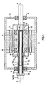
- FIG. 1 which is based on known embodiments of such machines (see, for example, the aforementioned US-A-font).
- the device generally designated 2 comprises a fixed, located at room temperature outer housing 3 with a stator winding 4.
- a rotor 5 is rotatably mounted about an axis of rotation A in bearings 6.
- the rotor has a vacuum vessel 7, in which, for example, hollow-cylindrical, torque-transmitting suspension elements 8 a winding support 9 is mounted with a HTS winding 10.
- this winding support is concentric to the axis of rotation A extending in the axial direction, cylindrical cavity 12 is present.
- the winding support is designed vacuum-tight with respect to this cavity.
- the hollow space advantageously extends axially into a region outside of the outer housing 3.
- a vacuum-tight neck tube 13 which leads from the region of the winding carrier to the outside and serves on its warmer side facing away from the winding carrier, with an expansion bellows 14 for a length compensation Is provided.
- the superconducting device 2 also has, for indirect cooling of the winding 10 via heat-conducting elements, a refrigeration unit 15, of which only one cold head 16 is shown.
- the refrigeration unit can in particular be a cryocooler of the Gifford-McMahon type.
- a pulse tube refrigerator or split Stirling cooler is selected as a regenerative cryocooler.
- the cold head 16 and thus all essential, other parts of the refrigeration unit 15 are outside the rotor 5 and the outer housing 3.
- additional parts such as warm pressure equalization tank, Gukapillaren, pressure relief valves to protect the system against overpressure during warming are not shown in the figure, but generally known.
- the cold part of the illustrated cold head 16 should be connected in good heat-conducting manner with an in particular cylindrical heat transfer body 18.
- This heat transfer body protrudes through the neck tube 13 into the cavity 12 of the winding support 9, with respect to the wall 13a of the neck tube and the wall 9a of the cavity, a hollow cylindrical annular gap 19 is maintained.
- This annular gap has a significantly larger cross-section in the region of the winding carrier than in the region of the neck tube.
- the cavity 12 of the winding support 9 is closed on the side facing away from the cold head 16 by the winding support itself. Since the cavity extends over the neck tube 13 through the outer housing 3 outwardly into the region of the cold head 16, a sealing of the annular gap is advantageously possible there.
- a sealing device 20 which is not detailed in the figure, is provided with at least one seal, which may be a ferrofluid seal and / or a labyrinth seal and / or a gap seal.
- the annular gap 19 is filled with a contact gas 21, preferably helium or for temperatures above 30 K operating temperature, for example, neon.
- the pressure is for example between 10 and 1000 mbar.
- a thermal contact between the heat transfer body 18 and the cavity 12 bounding wall of the winding body 9 is created.
- the Wicklungskorper should be sufficiently thermally conductive, ie, it has good heat-conducting parts between the wall 9a and the winding 10.
- the winding via the winding body 9, the contact gas 21 and the heat transfer body 18 is coupled in a simple manner thermally to the cold head 16 of the refrigeration unit.
- the heat exchange surfaces with respect to the contact gas 21 may optionally be provided with increasing measures, for example ribbing in the circumferential direction on the wall 9a or the opposite outside of the heat transfer body 18.
- Suitable materials for the cylindrical heat transfer body 18 are thermally highly conductive metals such as Al or Cu in question. If there are larger fields in the interior of the engine or its outer housing 3, which would lead to an impermissible eddy current heating, countermeasures are advantageous to take.
- the heat transfer body 18 may consist of a non-conductive material such as a ceramic, for example of Al 2 O 3 or AlN or monocrystalline sapphire material. He can also electrically isolated from each other and glued together compressed, consist essentially one-dimensional axially extending elements. Such elements may be tapes, sheets, wires such as copper enameled wires or braided strands.
- FIG. 2 the heat transfer between the heat transfer body 18 and the inside of the winding support 9 is illustrated during rotation: heat from the sufficiently thermally conductive winding support 9 reaches its inner, the cavity 12 delimiting wall with about 10 to 70 K depending on the HTS material used. There, a heat transfer to the co-rotating in the boundary layer contact gas 21, wherein the contact gas is heated. Due to the lower density of the warm gas and the lower centrifugal force, there is a buoyancy in the direction of the rotor axis A. There, the gas impinges on the colder heat transfer body 18 and gives off heat with cooling. At the same time it becomes denser and is thus conveyed outwards again due to the larger centrifugal force. The corresponding convection vortices 23 indicated in the figure run in the circumferential direction. In the figure, the self-adjusting heat flow is also indicated by arrowed lines 24.
- FIG. 3 is a cross section through the in FIG. 2 illustrated rotor 5 along a section line III-III 'illustrated in the case that it is in a standstill or in the cooling mode, thus being given no centrifugal force.
- the illustrated convection vortices or cells 25 are formed in the axial direction, which allow cooling from room temperature or cold holding in the stand-by mode of the rotor.
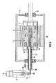
- superconducting device 28 differs from the superconducting device 2 after FIG. 1 essentially only by the design of the central heat transfer body.
- heat transfer body divided into two axially successively arranged parts, wherein a solid part 31 adjacent to the cold head 16 and only slightly protrudes into the interior of the outer housing 3.
- the heat transfer body is substantially hollow inside, for example designed as a thin-walled VA, or brass, or Cu or Al vessel and for heat transport as a heat pipe 32 after the "heat pipe” or "thermosiphon” Designed.
- the heat pipe 32 is filled with a heat transfer gas 33 such as Ne.
- heat is conveyed by evaporation and condensation of the heat transport gas, for example when using neon at 27 K, wherein the condensation takes place at the interface 34 between the solid part 31 and the heat pipe 32.
- the condensation takes place at the interface 34 between the solid part 31 and the heat pipe 32.
- this can be in a conventional manner with internals in the form of a wick, for example, equipped with a stainless steel wire sponge.
- the superconducting device 28 according to FIG. 4
- the heat transfer by means of the contact gas 21 between the winding support wall 9a and the massive, thermally connected to the cold head 16 of the refrigeration device part 31 of the heat transfer body is not directly or directly.
- the heat transfer gas 33 is introduced into the heat transfer path, so that an indirect (indirect) cooling of the contact gas 21 is provided by the cold solid part 31 here.
- FIG. 5 A refinement of the superconducting device according to FIG. 4 with such indirect cooling of the contact gas goes out FIG. 5 out.
- this designated 35 superconducting device of the cold head 16 of a refrigeration unit from the hollow shaft is pulled laterally, for example, by 0.5 m to several meters.
- a heat pipe 36 provided in the region of the winding 10 is filled with a heat transport gas 33 such as Ne after the head-pipe principle. It is laterally up to a sealing device 38 outside the outer housing. 3 extended over a vacuum-insulated support tube 37.
- This support tube, together with a concentrically arranged additional tube, forms a thin gas gap 42 through which the contact gas 21 reaches the sealing device 38, so that the sealing of the annular gap 19 receiving the contact gas 21 takes place there as well.
- a thin, passing through the sealing device 38, fixed connection line 39 is provided.
- This vacuum-insulated connecting line leads to the outside to a condenser 40, which is in thermal contact with a cold head 16 of a refrigeration unit via a heat transfer body 41.
- a support bearing 44 can be provided to avoid vibrations of the relatively long, rigidly connected to the heat pipe 36 support tube 37.
Landscapes
- Engineering & Computer Science (AREA)
- Power Engineering (AREA)
- Superconductive Dynamoelectric Machines (AREA)
- Motor Or Generator Cooling System (AREA)
- Containers, Films, And Cooling For Superconductive Devices (AREA)
Claims (13)
- Dispositif (2) supraconducteur- comprenant un rotor (5) qui est monté tournant autour d'un axe (A) de rotation et qui a au moins un enroulement (10) supraconducteur, dont les conducteurs sont disposés dans un support (9) d'enroulement réalisé de manière à conduire la chaleur,
et- comprenant un groupe (15) frigorifique qui a au moins une tête (16) froide qui est couplée thermiquement à l'enroulement (10), qui se trouve de manière fixe à l'extérieur du rotor (5) et qui est reliée rigidement et d'une manière conductrice de la chaleur à un corps (18, 30) de transmission de la chaleur, notamment cylindrique, qui pénètre dans le rotor (5),caractériséa) en ce que le support (9) d'enroulement est équipé d'une cavité (12) cylindrique, centrale, s'étendant dans la direction de l'axe,b) en ce que le corps (18, 30) de transmission de la chaleur pénètre dans la cavité (12) du support (9) de l'enroulement en maintenant un intervalle (19) annulaire cylindrique creux jusque dans la partie de l'enroulement (10),
ainsi quec) en ce que l'intervalle (19) annulaire est rempli au moins dans la partie du support (9) de l'enroulement d'un gaz (21) de contact pour la transmission de la chaleur entre le support (9) de l'enroulement et le corps (18, 30) de transmission de la chaleur et est rendu étanche au gaz. - Dispositif suivant la revendication 1, caractérisé en ce que la cavité (12) est fermée d'un côté par le support (9) de l'enroulement et l'intervalle (19) annulaire est rendue étanche du côté tourné vers la tête (16, 30) froide par un dispositif (20, 30) d'étanchéité ayant des parties qui tournent en même temps.
- Dispositif suivant la revendication 2, caractérisé en ce que le dispositif d'étanchéité a au moins une étanchéité choisie dans le groupe d'une étanchéité ferrofluidique, d'une étanchéité à labyrinthe et d'une étanchéité à fente.
- Dispositif suivant l'une des revendications précédentes, caractérisé en ce que le corps (30) de transmission de la chaleur est réalisé, au moins dans la partie du support (9) de l'enroulement, en tube (32, 36) caloporteur à la manière d'un heat-pipe, qui est rempli d'un gaz (37) de transport de la chaleur prévu pour la liaison thermique entre la tête (16) froide et le gaz (21) de contact se trouvant dans l'intervalle (19) annulaire dans la partie du corps (9) de l'enroulement.
- Dispositif suivant la revendication 4, caractérisé en ce que le corps (30) de transmission de la chaleur a une partie (31) pleine pénétrant dans le rotor et le tube (32) caloporteur.
- Dispositif suivant la revendication 4, caractérisé en ce que le tube (36) caloporteur prend, au moins dans le rotor, toute la longueur axiale du corps de transmission de la chaleur et à l'extérieur du rotor il est prévu, entre la tête (16) froide et le tube (36) caloporteur, un conduit (39) de liaison pour le gaz (33) de transport de la chaleur.
- Dispositif suivant la revendication 6, caractérisé en ce que le gaz (33) de transport de la chaleur est couplé thermiquement à la tête (16) froide par un condenseur (40) dans le conduit (39) de liaison.
- Dispositif suivant l'une des revendications précédentes, caractérisé en ce que le groupe (15) frigorifique a au moins un cryorefroidisseur, notamment régénératif.
- Dispositif suivant la revendication 8, caractérisé en ce que le cryorefroidisseur est un refroidisseur à tube pulsé ou un refroidisseur Split-Stirling ou un refroidisseur Gifford-McMahon.
- Dispositif suivant l'une des revendications précédentes, caractérisé par une constitution en plusieurs étages de la tête froidie.
- Dispositif suivant la revendication 10, caractérisé en ce que la tête froide a deux étages froids, le premier étage étant relié thermiquement à une entrée de courant ou à un écran de rayonnement et le deuxième étage étant relié thermiquement et rigidement au corps de transmission de la chaleur.
- Dispositif suivant l'une des revendications précédentes, caractérisé en ce que l'enroulement supraconducteur peut être maintenu au moyen de la tête froide à une température inférieure à 77 K.
- Dispositif suivant l'une des revendications précédentes, caractérisé en ce que les conducteurs de l'enroulement comportent du matériau supraconducteur métallique à basse Tc ou du matériau supraconducteur en oxyde métallique à haute Tc.
Applications Claiming Priority (3)
| Application Number | Priority Date | Filing Date | Title |
|---|---|---|---|
| DE10039964 | 2000-08-16 | ||
| DE10039964A DE10039964A1 (de) | 2000-08-16 | 2000-08-16 | Supraleitungseinrichtung mit einer Kälteeinheit zur Kühlung einer rotierenden, supraleitenden Wicklung |
| PCT/DE2001/002977 WO2002015370A1 (fr) | 2000-08-16 | 2001-08-03 | Dispositif supraconducteur muni d'une unite de refroidissement pour refroidir un enroulement supraconducteur en rotation |
Publications (2)
| Publication Number | Publication Date |
|---|---|
| EP1310035A1 EP1310035A1 (fr) | 2003-05-14 |
| EP1310035B1 true EP1310035B1 (fr) | 2008-12-03 |
Family
ID=7652578
Family Applications (1)
| Application Number | Title | Priority Date | Filing Date |
|---|---|---|---|
| EP01956420A Expired - Lifetime EP1310035B1 (fr) | 2000-08-16 | 2001-08-03 | Dispositif supraconducteur muni d'une unite de refroidissement pour refroidir un enroulement supraconducteur en rotation |
Country Status (6)
| Country | Link |
|---|---|
| US (1) | US7285881B2 (fr) |
| EP (1) | EP1310035B1 (fr) |
| JP (1) | JP3834288B2 (fr) |
| AT (1) | ATE416507T1 (fr) |
| DE (2) | DE10039964A1 (fr) |
| WO (1) | WO2002015370A1 (fr) |
Families Citing this family (33)
| Publication number | Priority date | Publication date | Assignee | Title |
|---|---|---|---|---|
| US7272938B2 (en) | 2002-03-14 | 2007-09-25 | Siemens Aktiengesellschaft | Superconducting device with a cold head of a refrigeration unit with a thermosyphon effect thermally coupled to a rotating superconducting winding |
| DE10211568B4 (de) * | 2002-03-15 | 2004-01-29 | Siemens Ag | Kälteanlage für zu kühlende Teile einer Einrichtung |
| DE10231434A1 (de) | 2002-05-15 | 2003-12-04 | Siemens Ag | Einrichtung der Supraleitungstechnik mit thermisch an eine rotierende supraleitende Wicklung angekoppeltem Kaltkopf einer Kälteeinheit |
| DE10221639B4 (de) * | 2002-05-15 | 2004-06-03 | Siemens Ag | Einrichtung der Supraleitungstechnik mit einem supraleitenden Magneten und einer Kälteeinheit |
| DE10250200A1 (de) * | 2002-10-28 | 2004-05-13 | Siemens Ag | Ladegenerator für Gleichstrom-Bordnetze von Wasser-, Land- und Luftfahrzeugen, insbesondere von Unterwasserschiffen |
| DE10321463A1 (de) * | 2003-05-13 | 2004-12-16 | Siemens Ag | Supraleitende Maschineneinrichtung mit einer supraleitenden Wicklung und einer Thermosyphon-Kühlung |
| DE10335040B4 (de) * | 2003-08-01 | 2009-09-03 | Siemens Ag | Elektrische Maschine mit ferromagnetischem Polkern ihres Rotors |
| DE102005004858A1 (de) * | 2005-02-02 | 2006-08-10 | Siemens Ag | Maschineneinrichtung mit Thermosyphon-Kühlung ihrer supraleitenden Rotorwicklung |
| DE102005005283A1 (de) * | 2005-02-04 | 2006-08-17 | Siemens Ag | Maschinenanlage mit Thermosyphon-Kühlung ihrer supraleitenden Rotorwicklung |
| DE102005028414B4 (de) * | 2005-06-20 | 2011-12-08 | Siemens Aktiengesellschaft | Einrichtung zur Erzeugung eines gepulsten Magnetfelds |
| US20070007844A1 (en) * | 2005-07-08 | 2007-01-11 | Levitronics, Inc. | Self-sustaining electric-power generator utilizing electrons of low inertial mass to magnify inductive energy |
| DE102006046688B3 (de) * | 2006-09-29 | 2008-01-24 | Siemens Ag | Kälteanlage mit einem warmen und einem kalten Verbindungselement und einem mit den Verbindungselementen verbundenen Wärmerohr |
| DE102007017795A1 (de) | 2007-04-16 | 2008-10-30 | Siemens Ag | Maschineneinrichtung |
| DE102009022960A1 (de) * | 2009-05-28 | 2010-12-02 | Siemens Aktiengesellschaft | Kühlung supraleitender Maschinen |
| US20110042967A1 (en) * | 2009-08-19 | 2011-02-24 | Winter Curt B | Electric generator driven by combustion engine and having fluid cooling |
| US9407126B2 (en) * | 2009-12-30 | 2016-08-02 | Fundacion Tecnalia Research & Innovation | Direct-drive superconducting synchronous generator for a wind turbine |
| US20120112571A1 (en) * | 2010-11-09 | 2012-05-10 | General Electric Company | Encapsulated stator assembly |
| US8332004B2 (en) | 2010-12-23 | 2012-12-11 | General Electric Company | System and method for magnetization of rare-earth permanent magnets |
| DE102011079968B4 (de) * | 2011-07-28 | 2014-10-09 | Siemens Aktiengesellschaft | Kühleinrichtung mit dochtartigem Material zum Transport von Kühlmittel |
| KR101273642B1 (ko) * | 2012-03-07 | 2013-06-17 | 현대중공업 주식회사 | 전도 냉각 방식 초전도 회전기 |
| US9331552B2 (en) * | 2013-06-13 | 2016-05-03 | Tesla Motors, Inc. | Rotor assembly with heat pipe cooling system |
| JP2017058079A (ja) * | 2015-09-17 | 2017-03-23 | 株式会社東芝 | 極低温冷凍機用蓄冷材、極低温蓄冷器、蓄冷型極低温冷凍機及び蓄冷型極低温冷凍機を備えたシステム |
| CN107240980B (zh) * | 2017-06-26 | 2024-04-12 | 浙江嘉熙科技股份有限公司 | 热超导传热轴、具有热超导传热轴的电动机及制备方法 |
| US10704693B2 (en) * | 2018-03-30 | 2020-07-07 | Varian Semiconductor Equipment Associates, Inc. | Cryogenic ferrofluid sealed rotary union |
| EP3588749A1 (fr) * | 2018-06-29 | 2020-01-01 | Celeroton AG | Machine électrique |
| CN111023877B (zh) * | 2019-12-09 | 2025-06-17 | 南方科技大学 | 一种磁流体旋转换热器 |
| FR3106943B1 (fr) | 2020-02-05 | 2023-05-26 | Leviathan Dynamics | Dispositif de refroidissement de rotor et machine tournante le comportant |
| CN111900807B (zh) * | 2020-07-21 | 2023-11-17 | 福建清诚科技有限公司 | 一种智能穿戴设备 |
| CN114803524A (zh) * | 2021-01-19 | 2022-07-29 | 中国航天科工飞航技术研究院(中国航天海鹰机电技术研究院) | 用于低温环境下超导磁体的支撑杆结构及超导磁体 |
| CN114301216A (zh) * | 2021-12-22 | 2022-04-08 | 东部超导科技(苏州)有限公司 | 一种散热组件及内置有该散热组件的超导电机 |
| CN115333329B (zh) * | 2022-06-23 | 2023-04-07 | 北京航天试验技术研究所 | 双蒸发冷凝循环的氢能飞机高温超导电机冷却装置及方法 |
| CN115664119B (zh) * | 2022-12-09 | 2023-03-10 | 大庆市晟威机械制造有限公司 | 一种基于热管散热的永磁电动机 |
| FR3166770A1 (fr) * | 2024-09-20 | 2026-03-27 | Airbus (S.A.S.) | Système de bobine pour un moteur supraconducteur |
Family Cites Families (41)
| Publication number | Priority date | Publication date | Assignee | Title |
|---|---|---|---|---|
| US3000322A (en) * | 1957-08-27 | 1961-09-19 | Fostoria Corp | Motor driven pump |
| FR2218681B1 (fr) * | 1973-02-21 | 1977-07-29 | Anvar | |
| US4039870A (en) * | 1975-07-17 | 1977-08-02 | Westinghouse Electric Corporation | Integrated annular supporting structure and damper shield for superconducting rotor assembly of dynamoelectric machine |
| DE2605593C3 (de) * | 1976-02-12 | 1982-03-18 | Kraftwerk Union AG, 4330 Mülheim | Supraleitende Erregerwicklung für den Läufer eines Turbogenerators |
| JPS5320508A (en) * | 1976-08-11 | 1978-02-24 | Hitachi Ltd | Super conducting rotor |
| US4117357A (en) * | 1977-04-15 | 1978-09-26 | Electric Power Research Institute, Inc. | Flexible coupling for rotor elements of a superconducting generator |
| US4250418A (en) * | 1978-05-11 | 1981-02-10 | Electric Power Research Institute, Inc. | Superconducting generator and method |
| JPS5553173A (en) * | 1978-10-16 | 1980-04-18 | Hitachi Ltd | Superconductive rotor |
| JPS5728540A (en) * | 1980-07-23 | 1982-02-16 | Hitachi Ltd | Refrigerant feed and exhaust device for superconductive generator |
| JPS5797340A (en) * | 1980-12-08 | 1982-06-17 | Hitachi Ltd | Liquid helium feeder for superconductive rotary machine |
| JPS5829367A (ja) * | 1981-08-14 | 1983-02-21 | Hitachi Ltd | 超電導回転子 |
| JPS5879465A (ja) * | 1981-10-31 | 1983-05-13 | Hitachi Ltd | 超電導回転子の冷媒給排装置 |
| JPS58144569A (ja) * | 1982-02-19 | 1983-08-27 | Hitachi Ltd | 超電導回転子 |
| US4914328A (en) * | 1984-01-11 | 1990-04-03 | Electric Power Research Institute | Electrical machine with a superconducting rotor having an improved warm damper shield and method of making same |
| US4583014A (en) * | 1984-09-26 | 1986-04-15 | Westinghouse Electric Corp. | Dynamoelectric machine with a rotor having a superconducting field winding and damper winding |
| JPH01129766A (ja) | 1987-11-16 | 1989-05-23 | Hitachi Ltd | 超電導回転子 |
| JPH01144356A (ja) * | 1987-11-30 | 1989-06-06 | Toshiba Corp | 超電導回転電機 |
| JP2638658B2 (ja) | 1990-03-28 | 1997-08-06 | 超電導発電関連機器・材料技術研究組合 | 超電導回転電機 |
| EP0495681A2 (fr) * | 1991-01-17 | 1992-07-22 | Yoshihiro Ohnishi | Machine tournante à superconducteurs |
| JP2635228B2 (ja) * | 1991-03-15 | 1997-07-30 | 超電導発電関連機器・材料技術研究組合 | 超電導回転電機の回転子 |
| JPH06303760A (ja) * | 1993-04-12 | 1994-10-28 | Chodendo Hatsuden Kanren Kiki Zairyo Gijutsu Kenkyu Kumiai | 超電導回転電機の回転子 |
| US5482919A (en) * | 1993-09-15 | 1996-01-09 | American Superconductor Corporation | Superconducting rotor |
| WO1996000462A1 (fr) * | 1994-06-23 | 1996-01-04 | Elin Motoren Gesellschaft M.B.H | Systeme de refroidissement pour moteur |
| JPH0866003A (ja) * | 1994-08-11 | 1996-03-08 | Chodendo Hatsuden Kanren Kiki Zairyo Gijutsu Kenkyu Kumiai | 超電導回転電機 |
| DE19604805C2 (de) | 1996-02-09 | 2001-03-08 | Siemens Ag | Anlage der Supraleitungstechnik mit einer indirekt zu kühlenden supraleitenden Einrichtung und einer Stromzuführungsvorrichtung |
| US5774032A (en) * | 1996-08-23 | 1998-06-30 | General Electric Company | Cooling arrangement for a superconducting coil |
| US5880547A (en) * | 1997-07-17 | 1999-03-09 | Reliance Electric Industrial Company | Internal torque tube for superconducting motor |
| US6169352B1 (en) * | 1997-07-21 | 2001-01-02 | University Of Chicago | Trapped field internal dipole superconducting motor generator |
| JP3853515B2 (ja) | 1998-05-07 | 2006-12-06 | 関西電力株式会社 | 高温超電導回転電機の界磁巻線 |
| GB2339975A (en) * | 1998-07-27 | 2000-02-09 | Asea Brown Boveri | Rotating electric machine stator |
| US6376943B1 (en) * | 1998-08-26 | 2002-04-23 | American Superconductor Corporation | Superconductor rotor cooling system |
| US6351045B1 (en) * | 1999-09-30 | 2002-02-26 | Reliance Electric Technologies, Llc | Croyogenic rotary transfer coupling for superconducting electromechanical machine |
| US6489701B1 (en) * | 1999-10-12 | 2002-12-03 | American Superconductor Corporation | Superconducting rotating machines |
| EP1325239B1 (fr) * | 2000-10-09 | 2004-04-14 | Siemens Aktiengesellschaft | Dispositif comportant un rotor et des paliers magnetiques pour le logement sans contact du rotor |
| DE10057664A1 (de) * | 2000-11-21 | 2002-05-29 | Siemens Ag | Supraleitungseinrichtung mit einem thermisch an eine rotierende,supraleitende Wicklung angekoppelten Kaltkopf einer Kälteeinheit |
| US6727633B2 (en) * | 2001-05-15 | 2004-04-27 | General Electric Company | High temperature super-conducting synchronous rotor coil support with tension rods and method for assembly of the coil support |
| US6727609B2 (en) * | 2001-08-08 | 2004-04-27 | Hamilton Sundstrand Corporation | Cooling of a rotor for a rotary electric machine |
| US7272938B2 (en) * | 2002-03-14 | 2007-09-25 | Siemens Aktiengesellschaft | Superconducting device with a cold head of a refrigeration unit with a thermosyphon effect thermally coupled to a rotating superconducting winding |
| US6794792B2 (en) * | 2002-11-13 | 2004-09-21 | General Electric Company | Cold structural enclosure for multi-pole rotor having super-conducting field coil windings. |
| US7548000B2 (en) * | 2004-10-18 | 2009-06-16 | General Electric Company | Multilayer radiation shield |
| US7312544B2 (en) * | 2005-02-15 | 2007-12-25 | General Electric Company | Fluid transfer device and method for conveying fluid to a rotating member |
-
2000
- 2000-08-16 DE DE10039964A patent/DE10039964A1/de not_active Withdrawn
-
2001
- 2001-08-03 EP EP01956420A patent/EP1310035B1/fr not_active Expired - Lifetime
- 2001-08-03 JP JP2002520386A patent/JP3834288B2/ja not_active Expired - Fee Related
- 2001-08-03 US US10/344,943 patent/US7285881B2/en not_active Expired - Fee Related
- 2001-08-03 DE DE50114548T patent/DE50114548D1/de not_active Expired - Lifetime
- 2001-08-03 AT AT01956420T patent/ATE416507T1/de not_active IP Right Cessation
- 2001-08-03 WO PCT/DE2001/002977 patent/WO2002015370A1/fr not_active Ceased
Also Published As
| Publication number | Publication date |
|---|---|
| ATE416507T1 (de) | 2008-12-15 |
| DE10039964A1 (de) | 2002-03-07 |
| DE50114548D1 (de) | 2009-01-15 |
| US7285881B2 (en) | 2007-10-23 |
| EP1310035A1 (fr) | 2003-05-14 |
| JP3834288B2 (ja) | 2006-10-18 |
| WO2002015370A8 (fr) | 2002-05-16 |
| WO2002015370A1 (fr) | 2002-02-21 |
| US20060158059A1 (en) | 2006-07-20 |
| JP2004507200A (ja) | 2004-03-04 |
Similar Documents
| Publication | Publication Date | Title |
|---|---|---|
| EP1310035B1 (fr) | Dispositif supraconducteur muni d'une unite de refroidissement pour refroidir un enroulement supraconducteur en rotation | |
| EP1336236B1 (fr) | Dispositif supraconducteur muni d'une tete de refroidissement d'une unite de refroidissement, thermiquement couplee a un enroulement supraconducteur rotatif | |
| EP1325239B1 (fr) | Dispositif comportant un rotor et des paliers magnetiques pour le logement sans contact du rotor | |
| EP1313959B1 (fr) | Palier magnetique destine a soutenir un arbre rotatif au moyen d'un materiau supraconducteur a tc elevee | |
| EP1504516B1 (fr) | Dispositif de supraconductivite a unite de refroidissement dotee d'une tete de refroidissement thermiquement couplee a une bobine supraconductrice rotative | |
| EP1636894B1 (fr) | Systeme a moteur supraconducteur presentant un bobinage supraconducteur et un refroidissement par thermosiphon | |
| EP1206667B1 (fr) | Dispositif supraconducteur comportant une unite refrigerante pour un enroulement supraconducteur rotatif | |
| EP3491724B1 (fr) | Rotor comprenant un ensemble bobine et un support d'enroulements | |
| EP2786472B2 (fr) | Machine électrique | |
| WO2006082194A1 (fr) | Installation motrice a refroidissement par thermosiphon de son enroulement rotorique supraconductrice | |
| EP1670128A2 (fr) | Système et procédé de refroidissement d'une machine de rotation supraconductrice | |
| DE102010001378A1 (de) | Supraleitende Vorrichtung | |
| WO2003079522A1 (fr) | Dispositif supraconducteur comprenant une tete a froid d'une unite de refroidissement a effet thermosiphon, cette tete a froid etant thermiquement reliee a un enroulement supraconducteur rotatif | |
| EP1536153A1 (fr) | Palier magnétique avec un supraconducteur logé dans une boíte annulaire vide | |
| DE102005004858A1 (de) | Maschineneinrichtung mit Thermosyphon-Kühlung ihrer supraleitenden Rotorwicklung | |
| WO2020038909A1 (fr) | Rotor comprenant un enroulement supraconducteur pour le fonctionnement en mode électrique permanent | |
| EP3205005A2 (fr) | Machine électrique | |
| DE10211363A1 (de) | Supraleitungseinrichtung mit einem thermisch an eine rotierende, supraleitende Wicklung angekoppelten Kaltkopf einer Kälteeinheit mit Thermosyphoneffekt | |
| US4238700A (en) | Electrical machine having an improved cooling system for a rotary superconductive winding | |
| DE10106552A1 (de) | Maschine mit einer in einem Wicklungsträger angeordneten supraleitenden Wicklung sowie mit Mitteln zur Halterung des Wicklungsträgers | |
| DE102009009127A1 (de) | Spule für ein supraleitendes Magnetlager | |
| DE19938985A1 (de) | Einrichtung der Supraleitungstechnik mit einer rotierenden, supraleitenden Wicklung | |
| DE102013213242A1 (de) | Spuleneinrichtung mit Spule und Kühlvorrichtung sowie Verfahren zur Kühlung einer Spule |
Legal Events
| Date | Code | Title | Description |
|---|---|---|---|
| PUAI | Public reference made under article 153(3) epc to a published international application that has entered the european phase |
Free format text: ORIGINAL CODE: 0009012 |
|
| 17P | Request for examination filed |
Effective date: 20030113 |
|
| AK | Designated contracting states |
Designated state(s): AT BE CH CY DE DK ES FI FR GB GR IE IT LI LU MC NL PT SE TR |
|
| GRAP | Despatch of communication of intention to grant a patent |
Free format text: ORIGINAL CODE: EPIDOSNIGR1 |
|
| RTI1 | Title (correction) |
Free format text: SUPERCONDUCTOR DEVICE COMPRISING A COOLING UNIT FOR COOLING A ROTATING SUPRACONDUCTIVE COIL |
|
| GRAS | Grant fee paid |
Free format text: ORIGINAL CODE: EPIDOSNIGR3 |
|
| GRAS | Grant fee paid |
Free format text: ORIGINAL CODE: EPIDOSNIGR3 |
|
| GRAA | (expected) grant |
Free format text: ORIGINAL CODE: 0009210 |
|
| AK | Designated contracting states |
Kind code of ref document: B1 Designated state(s): AT BE CH CY DE DK ES FI FR GB GR IE IT LI LU MC NL PT SE TR |
|
| REG | Reference to a national code |
Ref country code: GB Ref legal event code: FG4D Free format text: NOT ENGLISH |
|
| REG | Reference to a national code |
Ref country code: CH Ref legal event code: EP |
|
| REG | Reference to a national code |
Ref country code: IE Ref legal event code: FG4D Free format text: LANGUAGE OF EP DOCUMENT: GERMAN |
|
| REF | Corresponds to: |
Ref document number: 50114548 Country of ref document: DE Date of ref document: 20090115 Kind code of ref document: P |
|
| PG25 | Lapsed in a contracting state [announced via postgrant information from national office to epo] |
Ref country code: ES Free format text: LAPSE BECAUSE OF FAILURE TO SUBMIT A TRANSLATION OF THE DESCRIPTION OR TO PAY THE FEE WITHIN THE PRESCRIBED TIME-LIMIT Effective date: 20090314 |
|
| NLV1 | Nl: lapsed or annulled due to failure to fulfill the requirements of art. 29p and 29m of the patents act | ||
| PG25 | Lapsed in a contracting state [announced via postgrant information from national office to epo] |
Ref country code: NL Free format text: LAPSE BECAUSE OF FAILURE TO SUBMIT A TRANSLATION OF THE DESCRIPTION OR TO PAY THE FEE WITHIN THE PRESCRIBED TIME-LIMIT Effective date: 20081203 Ref country code: FI Free format text: LAPSE BECAUSE OF FAILURE TO SUBMIT A TRANSLATION OF THE DESCRIPTION OR TO PAY THE FEE WITHIN THE PRESCRIBED TIME-LIMIT Effective date: 20081203 |
|
| REG | Reference to a national code |
Ref country code: IE Ref legal event code: FD4D |
|
| PG25 | Lapsed in a contracting state [announced via postgrant information from national office to epo] |
Ref country code: IE Free format text: LAPSE BECAUSE OF FAILURE TO SUBMIT A TRANSLATION OF THE DESCRIPTION OR TO PAY THE FEE WITHIN THE PRESCRIBED TIME-LIMIT Effective date: 20081203 |
|
| PG25 | Lapsed in a contracting state [announced via postgrant information from national office to epo] |
Ref country code: PT Free format text: LAPSE BECAUSE OF FAILURE TO SUBMIT A TRANSLATION OF THE DESCRIPTION OR TO PAY THE FEE WITHIN THE PRESCRIBED TIME-LIMIT Effective date: 20090504 Ref country code: SE Free format text: LAPSE BECAUSE OF FAILURE TO SUBMIT A TRANSLATION OF THE DESCRIPTION OR TO PAY THE FEE WITHIN THE PRESCRIBED TIME-LIMIT Effective date: 20090303 |
|
| PLBE | No opposition filed within time limit |
Free format text: ORIGINAL CODE: 0009261 |
|
| STAA | Information on the status of an ep patent application or granted ep patent |
Free format text: STATUS: NO OPPOSITION FILED WITHIN TIME LIMIT |
|
| PG25 | Lapsed in a contracting state [announced via postgrant information from national office to epo] |
Ref country code: DK Free format text: LAPSE BECAUSE OF FAILURE TO SUBMIT A TRANSLATION OF THE DESCRIPTION OR TO PAY THE FEE WITHIN THE PRESCRIBED TIME-LIMIT Effective date: 20081203 |
|
| 26N | No opposition filed |
Effective date: 20090904 |
|
| BERE | Be: lapsed |
Owner name: SIEMENS A.G. Effective date: 20090831 |
|
| PG25 | Lapsed in a contracting state [announced via postgrant information from national office to epo] |
Ref country code: MC Free format text: LAPSE BECAUSE OF NON-PAYMENT OF DUE FEES Effective date: 20090831 |
|
| REG | Reference to a national code |
Ref country code: CH Ref legal event code: PL |
|
| PG25 | Lapsed in a contracting state [announced via postgrant information from national office to epo] |
Ref country code: LI Free format text: LAPSE BECAUSE OF NON-PAYMENT OF DUE FEES Effective date: 20090831 Ref country code: CH Free format text: LAPSE BECAUSE OF NON-PAYMENT OF DUE FEES Effective date: 20090831 |
|
| PG25 | Lapsed in a contracting state [announced via postgrant information from national office to epo] |
Ref country code: BE Free format text: LAPSE BECAUSE OF NON-PAYMENT OF DUE FEES Effective date: 20090831 |
|
| PG25 | Lapsed in a contracting state [announced via postgrant information from national office to epo] |
Ref country code: GR Free format text: LAPSE BECAUSE OF FAILURE TO SUBMIT A TRANSLATION OF THE DESCRIPTION OR TO PAY THE FEE WITHIN THE PRESCRIBED TIME-LIMIT Effective date: 20090304 |
|
| PG25 | Lapsed in a contracting state [announced via postgrant information from national office to epo] |
Ref country code: AT Free format text: LAPSE BECAUSE OF NON-PAYMENT OF DUE FEES Effective date: 20090803 |
|
| PG25 | Lapsed in a contracting state [announced via postgrant information from national office to epo] |
Ref country code: LU Free format text: LAPSE BECAUSE OF NON-PAYMENT OF DUE FEES Effective date: 20090803 |
|
| PG25 | Lapsed in a contracting state [announced via postgrant information from national office to epo] |
Ref country code: TR Free format text: LAPSE BECAUSE OF FAILURE TO SUBMIT A TRANSLATION OF THE DESCRIPTION OR TO PAY THE FEE WITHIN THE PRESCRIBED TIME-LIMIT Effective date: 20081203 |
|
| PG25 | Lapsed in a contracting state [announced via postgrant information from national office to epo] |
Ref country code: CY Free format text: LAPSE BECAUSE OF FAILURE TO SUBMIT A TRANSLATION OF THE DESCRIPTION OR TO PAY THE FEE WITHIN THE PRESCRIBED TIME-LIMIT Effective date: 20081203 |
|
| PGFP | Annual fee paid to national office [announced via postgrant information from national office to epo] |
Ref country code: DE Payment date: 20151016 Year of fee payment: 15 |
|
| REG | Reference to a national code |
Ref country code: FR Ref legal event code: PLFP Year of fee payment: 16 |
|
| PGFP | Annual fee paid to national office [announced via postgrant information from national office to epo] |
Ref country code: IT Payment date: 20160830 Year of fee payment: 16 Ref country code: GB Payment date: 20160811 Year of fee payment: 16 |
|
| PGFP | Annual fee paid to national office [announced via postgrant information from national office to epo] |
Ref country code: FR Payment date: 20160823 Year of fee payment: 16 |
|
| REG | Reference to a national code |
Ref country code: DE Ref legal event code: R119 Ref document number: 50114548 Country of ref document: DE |
|
| PG25 | Lapsed in a contracting state [announced via postgrant information from national office to epo] |
Ref country code: DE Free format text: LAPSE BECAUSE OF NON-PAYMENT OF DUE FEES Effective date: 20170301 |
|
| GBPC | Gb: european patent ceased through non-payment of renewal fee |
Effective date: 20170803 |
|
| REG | Reference to a national code |
Ref country code: FR Ref legal event code: ST Effective date: 20180430 |
|
| PG25 | Lapsed in a contracting state [announced via postgrant information from national office to epo] |
Ref country code: GB Free format text: LAPSE BECAUSE OF NON-PAYMENT OF DUE FEES Effective date: 20170803 |
|
| PG25 | Lapsed in a contracting state [announced via postgrant information from national office to epo] |
Ref country code: FR Free format text: LAPSE BECAUSE OF NON-PAYMENT OF DUE FEES Effective date: 20170831 Ref country code: IT Free format text: LAPSE BECAUSE OF NON-PAYMENT OF DUE FEES Effective date: 20170803 |