EP1310189B1 - Arbeitstischsystem - Google Patents
Arbeitstischsystem Download PDFInfo
- Publication number
- EP1310189B1 EP1310189B1 EP02024741A EP02024741A EP1310189B1 EP 1310189 B1 EP1310189 B1 EP 1310189B1 EP 02024741 A EP02024741 A EP 02024741A EP 02024741 A EP02024741 A EP 02024741A EP 1310189 B1 EP1310189 B1 EP 1310189B1
- Authority
- EP
- European Patent Office
- Prior art keywords
- leg
- panels
- desk system
- top board
- panel
- Prior art date
- Legal status (The legal status is an assumption and is not a legal conclusion. Google has not performed a legal analysis and makes no representation as to the accuracy of the status listed.)
- Expired - Lifetime
Links
- 239000002344 surface layer Substances 0.000 description 7
- 239000004744 fabric Substances 0.000 description 6
- 239000000835 fiber Substances 0.000 description 6
- 239000002131 composite material Substances 0.000 description 3
- 239000000945 filler Substances 0.000 description 3
- 238000012986 modification Methods 0.000 description 3
- 230000004048 modification Effects 0.000 description 3
- 235000017166 Bambusa arundinacea Nutrition 0.000 description 2
- 235000017491 Bambusa tulda Nutrition 0.000 description 2
- 241001330002 Bambuseae Species 0.000 description 2
- 229920000742 Cotton Polymers 0.000 description 2
- 235000015334 Phyllostachys viridis Nutrition 0.000 description 2
- 241001417523 Plesiopidae Species 0.000 description 2
- 238000010521 absorption reaction Methods 0.000 description 2
- 239000011425 bamboo Substances 0.000 description 2
- 230000006835 compression Effects 0.000 description 2
- 238000007906 compression Methods 0.000 description 2
- 238000010276 construction Methods 0.000 description 2
- 238000009434 installation Methods 0.000 description 2
- 239000010410 layer Substances 0.000 description 2
- 229910052751 metal Inorganic materials 0.000 description 2
- 239000002184 metal Substances 0.000 description 2
- 238000000034 method Methods 0.000 description 2
- 239000011347 resin Substances 0.000 description 2
- 229920005989 resin Polymers 0.000 description 2
- 238000005728 strengthening Methods 0.000 description 2
- 229910000831 Steel Inorganic materials 0.000 description 1
- 229910052782 aluminium Inorganic materials 0.000 description 1
- XAGFODPZIPBFFR-UHFFFAOYSA-N aluminium Chemical compound [Al] XAGFODPZIPBFFR-UHFFFAOYSA-N 0.000 description 1
- 230000010485 coping Effects 0.000 description 1
- 238000004512 die casting Methods 0.000 description 1
- 238000007731 hot pressing Methods 0.000 description 1
- 238000003780 insertion Methods 0.000 description 1
- 230000037431 insertion Effects 0.000 description 1
- 238000005304 joining Methods 0.000 description 1
- 230000014759 maintenance of location Effects 0.000 description 1
- 239000000203 mixture Substances 0.000 description 1
- 238000012856 packing Methods 0.000 description 1
- 238000000059 patterning Methods 0.000 description 1
- 238000003825 pressing Methods 0.000 description 1
- 239000007787 solid Substances 0.000 description 1
- 238000003892 spreading Methods 0.000 description 1
- 239000010959 steel Substances 0.000 description 1
- 235000013311 vegetables Nutrition 0.000 description 1
Images






Classifications
-
- A—HUMAN NECESSITIES
- A47—FURNITURE; DOMESTIC ARTICLES OR APPLIANCES; COFFEE MILLS; SPICE MILLS; SUCTION CLEANERS IN GENERAL
- A47B—TABLES; DESKS; OFFICE FURNITURE; CABINETS; DRAWERS; GENERAL DETAILS OF FURNITURE
- A47B17/00—Writing-tables
- A47B17/02—Writing-tables with vertically-adjustable parts
-
- A—HUMAN NECESSITIES
- A47—FURNITURE; DOMESTIC ARTICLES OR APPLIANCES; COFFEE MILLS; SPICE MILLS; SUCTION CLEANERS IN GENERAL
- A47B—TABLES; DESKS; OFFICE FURNITURE; CABINETS; DRAWERS; GENERAL DETAILS OF FURNITURE
- A47B1/00—Extensible tables
Definitions
- the present invention relates to a desk system and, more particularly, to a desk system having a high degree of freedom of arranging top boards in various layouts according to conditions and purposes for uses as desk systems and capable of being easily assembled and recombined.
- Fig. 23 shows a representative conventional built-up work desk capable of being assembled in an optimum combination, taking into consideration the number of persons that will engage in the work to be carried out on the work desk and the purpose of the work.
- the work desk is assembled by extending beams b between legs a set up on the floor and fastening top boards c to the beams b with screws.
- a circular beam b' having the shape of a circular arc in a plan view is extended between the middle legs a , and a sectorial top board c' is fastened to the circular beam b' .
- This conventional built-up work desk needs beams of shapes conforming to a desired layout and, when the layout is changed, needs parts conforming to a new layout.
- the parts of the conventional built-up work desk cannot commonly be used for forming work desks of different layouts, and hence the built-up work desk is inevitably costly.
- fastening members such as bolts, are necessary for fastening the beams b to the legs a and fastening the top boards c to the beams b , assembling the built-up work desk needs much time and labor. From DE 91 10 690U a desk system according to the first part of claim 1 is known.
- Another object of the present invention is to provide a desk system facilitating installing screen panels for separating adjacent desk sections and/or opposite desk sections of the desk system, and laying cables for supplying power to office automation equipment through the desk sections.
- a desk system capable of being assembled in a desired form comprises the features of claim 1.
- the desk system can be formed in a desired form regardless of the plane shape of the top boards, the top boards can be easily rearranged without using any additional parts and using the common parts when the purpose of the desk system is changed. Since the top boards are supported by the top board support members on the leg panels, the height of the top boards from the leg panels can be adjusted simply by adjusting the height of the top board support members from the leg panels, regardless of the construction of the top boards.
- Spaces for receiving cables and support rods of screen panels may be formed between the longitudinally adjacent top boards extended between the leg panels and supported on the top board support members and/or between the laterally adjacent top boards.
- the desk system may further comprise screen panels provided with support rods to be fixedly inserted in holes formed in top walls of the leg panels.
- Desk sections for individual persons of the desk system can be separated by the screen panels.
- Each of the leg panels has a frame of a metal defining the shape of the leg panel, and a pair of side panels attached to the opposite sides of the frame.
- one of the side panels is detachable from the frame.
- the legs of the top plate support members and the support rods of the screen panels attached to the leg panels can be completely concealed for an improved appearance.
- the desk system can be disassembled and reassembled simply by removing the side panels.
- each top board support member is a structure having a shape resembling the inverted letter U in a front elevation and has a pair of legs and a cross beam connecting the upper ends of the pair of legs or a structure having a shape resembling the letter T in a front elevation and has a single leg and a cross beam connected to the upper end of the leg.
- the upper surface of the cross beam of the top board support member serves as a top board support surface, and the upper wall of the leg panel is provided with openings through which the legs or the leg of the top board support member is inserted in the leg panel and moved for height adjustment.
- upper end parts of the legs of the top board support member are bent perpendicularly and the cross beam is extended between the free ends of perpendicularly bent upper end parts, the top board is fastened to the upper surface of the cross beam, and a gap for wiring is formed between the adjacent top boards. Even when the top board support members for supporting the adjacent top boards are mounted on the single leg panel, the gap for wiring can be formed between the adjacent top boards.
- Cables can be easily neatly arranged under the top boards in the cable trough, and all the necessary wires and cables can be arranged under the top boards.
- the longitudinal beams extended between the leg panels and forming the cable trough serve as strengthening members that strengthen the desk system.
- Screen panel holding members may be attached to the longitudinal beams having opposite ends fastened to the leg panels, and the support rods of the screen panels may be set upright on the screen panel holding members.
- the screen panel holding member has an oblique surface of an inclination equal to the inclination of the longitudinal beam attached to the leg panels when the upper truncated part of the leg panel has a bevel surface, a holding projection that engages in an opening formed in the longitudinal beam is formed in an upper end part of the oblique surface, a threaded hole is formed in a lower end part of the oblique surface, and a hole for receiving a support rod for supporting the screen panel is formed in the upper surface of the screen panel holding member.
- An upper end part of the support rod for supporting the screen panel may be inserted in a vertical hole formed in the screen panel, and a height adjustment device for adjusting the height of the screen panel may be mounted on the support rod to adjust the height of the screen panel.
- the screen panel is formed by forming a fiber panel of regenerated vegetable fibers, such as regenerated bamboo fibers, and a solidifying reclaimed resin, spreading a filler sheet, such as a cotton sheet, over a surface of the fiber panel, covering the filler sheet with a fabric, subjecting the assembly of the fiber panel, the filler sheet and the fabric to hot-pressing to obtain a composite panel, and attaching a frame to the composite panel.
- regenerated vegetable fibers such as regenerated bamboo fibers
- a solidifying reclaimed resin spreading a filler sheet, such as a cotton sheet, over a surface of the fiber panel, covering the filler sheet with a fabric, subjecting the assembly of the fiber panel, the filler sheet and the fabric to hot-pressing to obtain a composite panel, and attaching a frame to the composite panel.
- a specific pattern may be formed in the fabric of the screen panel by pressing the fabric with a patterning die.
- the desk system may be provided with double-faced screen panel formed by joining the two composite panels back-to-back with the fabrics facing out to form a build-up panel, and attaching a frame to the built-up panel.
- an opposed-desk type desk system according to the present invention comprises leg panels 1, top boards 2, top board support members 3 for fixedly supporting the top boards 2 on the leg panels 2; beams 4 connecting the leg panels 1 and forming a cable trough, and screen panels 5.
- the leg panels 1 are paired by installing the two leg panels 1 laterally contiguously in a symmetrical shape.
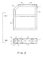
- Each leg panel 1 has a predetermined thickness and is formed in a vertically elongate rectangular shape. Opposed upper corners of the pair of leg panels 1 are truncated to form cut corners 1A defined by bevel surfaces 1a inclined at about 45° to a horizontal plane. When the pair of leg panels 1 are installed as shown in Fig. 1, the bevel surfaces 1a form a V-shaped groove. An upper corner of each leg panel 1 may be cut, instead of being truncated as shown in Fig. 3, to form a cut corner 1A defined by an L-shaped surface 1'a as shown in Fig. 4(A) or a round surface 1"a as shown in Fig. 4(B).
- the leg panel 1 has a steel frame 6, side panels 7 detachably attached to the opposite sides of the frame 6, a decorative panel 7a attached to the top surface 1b of the horizontal upper member of the frame 6, and a plate 7b attached to the outer surface of a vertical frame member extending from the lower end of the bevel surface 1a.
- Two pairs of openings 8 for receiving the pairs of leg parts 3a of the top board support members 3, and openings 9 for receiving support rods 10 for supporting the screen panels 5 are formed in the top surface 1b of the horizontal upper member of the frame 6.
- the leg panel 1 is provided with openings (or windows) 1h in its side panel 7. Cables are inserted through the openings 1h into the hollow leg panel 1.
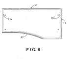
- the top board 2 shown in Fig. 6 is a strong, lightweight structure having a flat structure formed by sandwiching a honeycomb core between upper and lower panels, and a decorative frame 11 attached to the side surfaces of the flat structure.
- the edge 2a of a part in front of which a person is stationed for work of the top board 2 is formed in a shape conforming to the layout of the desk system.
- the top board 2 is chosen from a plurality of kinds of top boards 2 respectively having different shapes.
- the top board support member 3 is formed of aluminum by die casting.
- the top board support member 3 has the shape of the inverted letter U in a front elevation as shown in Figs. 1, 7, 8 and 9.
- the top board support member 3 has a pair of vertical leg parts 3a, horizontal arm parts 3b horizontally extending from the upper ends of the leg parts 3a, respectively, and a cross beam 3c joined to the extremities of the horizontal arm parts 3b.
- a plurality of holes 3d, three holes 3d in this embodiment, are formed in a longitudinal arrangement in each of the leg parts 3a.
- the leg parts 3a are inserted in the openings 8 formed in the top surface 1b of the leg panel 1, a screw is screwed through one of the holes 3d of each leg parts 3a in a threaded hole formed in the frame 6 of the leg panel 1 to support the top board 2 at a desired height.
- the cross beam 3c is provided with threaded holes 12. Screws are screwed through openings formed in the top board 2 in the threaded holes 12 to fasten the top board 2 to the cross beam. It is preferable, with a view to reducing time and labor necessary for assembling the desk system, to provided the cross beam 3c with a threaded hole 13 near one end of the cross bar 3c and a hole 12 near the other end of the cross beam 3c, to screw a headed screw in the threaded hole 13, to form a locking hole 13a having a round part that permits the passage of the head of the headed screw in the bottom wall of the top board 2, to engage the head of the headed bolt in the locking hole 13a of the top board 2, and to screw a screw through the hole 12 in a threaded hole formed in the top board 2.
- top boards 2 are fastened to the top board support members 3 such that gaps 130 for extending cables for supplying power to OA machines are formed between the laterally adjacent top boards 2 and between the longitudinally adjacent top boards 2.
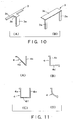
- a top board support member 3 shown in Fig. 10(A) or Fig. 10(B) may be used instead of the top board support member 3 shown in Fig. 7.
- the top board support member 3 shown in Fig. 10(A) has a single leg part 3a, a horizontal arm part 3b joined to the upper end of the leg part 3a, and a cross beam 3c formed integrally with or attached to the arm part 3b, and is formed in a T-shape in a front elevation.
- the top board support member 3 shown in Fig. 10(B) has two leg parts 3a, and a cross beam 3c formed integrally with or attached to the upper ends of the two leg parts 3a, and is formed in an inverted U-shape in a front elevation.
- the beam 4 is an elongate, rectangular metal plate provided with longitudinally arranged wiring holes 14.
- the beam 4 has a width corresponding to the length of the bevel surface 1a of the leg panel 1.
- the two beams 4 are set on the opposite bevel surfaces 1a to form a cable trough having a V-shaped cross section and having an open bottom 15 as shown in Fig. 1.
- Figs. 11(A) to 11(D) are end views of beams 4 in modifications.
- the beam 4 having an L-shaped cross section shown in Fig. 11(B) having a vertical wall 4c and a horizontal wall 4d is used to provide a cable trough for a desk system in which the leg panels 1 shown in Fig. 4(A) are used in pairs and are arranged at intervals in two rows.
- the beam 4 having a quadrantal cross section shown Fig. 11(D) is used to provide a cable trough for a desk system in which the leg panels 1 shown in Fig. 4(B) are used in pairs and are arranged at intervals in two rows.
- Figs. 12 to 15 show a part of the working desk system comprising a screen panel 5, screen panel holding members 16 for holding the screen panel 5 on the beam 4, and height adjusting devices 17 for adjusting the height of the screen panel 5.
- the height adjusting device 17 can be used for adjusting the height of the screen panels 5 of the opposed-desk type desk system shown in Fig. 1.
- the opposite ends of the beam 4 are fastened to the bevel surfaces 1a of the two leg panels 1 with screws, and the screen panel holding members 16 are attached to lower parts near the lower edge of the beam 4.
- the screen panel holding member 16 is a polygonal block having an oblique surface 16a inclined at an angle equal to the inclination of the beam 4.
- the screen panel holding member 16 is provided with a retaining projection 18 projects from an upper end part of the oblique surface 16a, and a threaded hole 19 in a lower end part of the oblique surface 16a.
- the retaining projection 18 is engaged in one of the openings 14 of the beam 4, and a screw 20 is screwed in the threaded hole 19 to fasten the screen panel holding member 16 to the beam 4.
- the screen panel holding member 16 is provided in its upper surface with a hole 21 for receiving a support rod 10 for supporting the screen panel 5.
- Acover plate 22 is attached to the vertical side surface of the screen panel holding member 16 to conceal the beam 4 and the support rod 10 supporting the screen panel 5.
- Fig. 14 shows the desk system shown in Fig. 12 in a state where the screen panel 5 is raised to its high position
- Fig. 15 shows the desk system shown in Fig. 12 in a state where the screen panel 5 is lowered to its low position
- the support rod 10 is provided with a plurality of longitudinally arranged through holes 23 for height adjustment. An upper end part of the support rod 10 is inserted in a hole 5a formed in the screen panel 5 to hold the screen panel 5 at a desired height.
- Figs. 16 and 17 show the height adjusting device 17 for adjusting the height of the screen panel 5.
- the height adjusting device 17 has a body 25 having the shape of an elongate rectangular solid and provided with a vertical hole 24 through which the support rod 10 supporting the screen panel 5 is extended vertically in one end part thereof and a horizontal hole 27 extending diametrically across the vertical hole 24, a locking bolt 26 axially slidably fitted in the horizontal hole 27, a knob 28 attached to a idle part of the locking bolt 26, and a compression spring 29 extended between an end wall of the knob 28 and an end wall 25a of the body 25 to push the locking bolt 26 into the height adjusting hole 23 of the support rod 10 extended through the vertical hole 24.
- Figs. 19 and 21 show the screen panel 5 provided with two side panels shown in Fig. 20.
- the side panel of the screen panel 5 has a base plate 30 of a size substantially corresponding to the size of the screen panel 5, a surface layer 31 covering the outer surfaces of the base plate 30, and a padding layer 32 formed by packing padding in a space between the base plate 30 and the surface layer 31.
- the base plates 30 are formed by solidifying a mixture of regenerated bamboo fibers and a resin, the surface layers 31 are fabrics, and the padding layer 32 is cotton.
- the layered base plate 30, the surface layer 31 and the padding 32 are compressed by press work in a flat shape.
- the surface of the surface layer 31 is embossed in a wavy shape.
- the surface of the surface layer 31 may be formed in an optional shape.
- the screen panel 5 is lightweight and excellent in shape retention and sound absorption, has a high strength, permits pinning, and facilitates disposal.
- the screen panel 5 shown in Figs. 19 and 21 is used in the opposite-desk type desk system as shown in Fig. 1.
- the screen panel 5 is constructed by placing the side panels each consisting of the base plate 30, the surface layer 31 and the padding 32 opposite to each other with a predetermined space formed between the base plates 30, and fixedly attaching a decorative frame 33 to the side panels.
- Figs. 22(A), 22(B) and 22(C) showscreenpanelconnectors for connecting the screen panels 5 such that the wiring gaps 34 are formed between the adjacent screen panels 5.
- a screen panel connector 35 shown in Fig. 22(A) has a straight part and round heads 35a formed on the opposite ends of the straight part, and is used for connecting the two laterally arranged screen panels 5.
- the round heads 35a are fitted in grooves 36 formed in end parts of the screen panels 5 to connect the screen plates 5 so that the wiring gap 34 is formed between the screen panels.
- a screen panel connector 35 shown in Fig. 22(B) has a T-shape in a plan view and is used for connecting three screen panels 5 extending in three directions, respectively.
- a screen panel connector 35 shown in Fig. 22(C) has a cross-shape in a plan view and is used for connecting four screen panels 5 extending in four directions, respectively.
- the frames 6 of the leg panels 1 of each of the three pairs each of the symmetrically combined leg panels 1 are fastened together with screws to combine the pair of leg panels 1 in a single leg.
- the beams 4 are fastened to the pairs of the leg panels 1 to connect the pairs of leg panels 1.
- the leg parts 3a of the top board support members 3 are inserted in the holes 8 formed in the top surfaces 1b of the horizontal upper members of the frames 6, the top board support members 3 are held at a desired height, and screws are screwed through the holes 3d corresponding to the desired height in the threaded holes formed in the frames 6 to fasten the top board support members to the leg panels 1.
- top boards 2 are fastened to the cross beams 3c of the top board support members 3 with the headed screws and the screws.
- each top board support member 3 Since the cross beam 3c of each top board support member 3 is shifted horizontally by a distance corresponding to the length of the horizontal arm parts 3b from a position corresponding to the leg parts 3a, the wiring gap 130is formed automatically between the adjacent top boards 2.
- the top board support members 3 supporting those top boards 2 are set at different heights, respectively.
- the support rods 10 are inserted in the holes 9 of the leg panels 1, the screen panel holding members 16 are fastened to the beams 4, the height adjusting devices 17 are positioned properly on the support rods 10 to locate the screen panels 5 at a desired height.
- the shelf can be simply supported on the leg panels 1 by inserting support rods for supporting the shelf through the gap 130 between the top boards 2 in holes 1d formed in the bevel surfaces 1a of the leg panels 1, and putting the shelf on the support rods.
- the desk system can be constructed in an optional layout regardless of the plane shape of the top boards, and the combination of the top boards can be changed by using the common parts when uses of the desk system requires because the top board support members are attached to the leg panels and the top boards are attached to the top board support members. Since the top boards are held by the top board support members on the leg panels, the height of the top boards from the leg panels can be adjusted simply by changing the vertical positions of the top board support members on the leg panels. Thus, the height of the top boards can be easily adjusted regardless of the construction of the top boards.
- Sections of the desk system for persons stationed opposite to each other and those stationed side by side can be separated from each other by fixedly inserting the support rods in the holes formed in the upper ends of the leg panels, and supporting the screen panels on the support rods.
- the desk system Since the leg parts of the top board support members attached to the leg panels and the support rods supporting the screen panels can be completely concealed by the cover plates 22, the desk system has an improved appearance. Work for changing the layout of the desk system can be performed simply by removing the cover plates.
- the desk system Since the end parts of the adjacent top boards are supported on the single leg panel, the number of the leg panels necessary for supporting the plurality of top boards is small, the desk system has a simple appearance, the numbers of the necessary parts is small and, hence, the desk system can be fabricated at a low cost.
- the gaps between the top boards facilitate the arrangement of cables for supplying power to OA machines to be operated on the desk system, and the installation of the support rods for supporting the screen panels on the leg panels.
- the top board support members can be easily attached to the leg panels by inserting the leg parts of the top board support members in the holes formed in the upper end surfaces of the leg panels and fastening the same to the leg panels, and the height of the top boards can be easily adjusted by adjusting the depth of insertion of the leg parts of the top board support members in the holes of the leg panels.
- the gap between the adjacent top boards can be easily formed by supporting the adjacent top boards by the top board support members on the single leg panel.
- the two paired leg panels are disposed with the upper cut parts thereof facing each other so as to form the concave space, and the beams are attached to the upper cut parts of the leg panels so as to form the cable trough in the concave space.
- the cable trough enables efficient work for laying cables, and the beams extended between the leg panels and forming the cable trough serve as strengthening members that strengthen the desk system.
- the screen panels are lightweight and strong, have a soft appearance, permit pinning, are satisfactorily capable of sound absorption, and facilitate disposal.
Landscapes
- Tables And Desks Characterized By Structural Shape (AREA)
- Dry Formation Of Fiberboard And The Like (AREA)
- Iron Core Of Rotating Electric Machines (AREA)
- Input Circuits Of Receivers And Coupling Of Receivers And Audio Equipment (AREA)
- Measurement And Recording Of Electrical Phenomena And Electrical Characteristics Of The Living Body (AREA)
- Liquid Crystal Substances (AREA)
- Liquid Crystal (AREA)
- Liquid Developers In Electrophotography (AREA)
Claims (14)
- Arbeitstischsystem, welches in einer gewünschten Form zusammenzusetzen ist, enthaltend:Beinplatten (1) gewünschter Dicke;Oberplatten-Stützteile (3), welche jeweils eine obere Stützfläche (3c) aufweisen und an der Beinplatte (1) so zu befestigen sind, daß die obere Stützfläche (3c) sich oberhalb der Beinplatte (1) erstreckt;Oberplatten (2) gewünschter Formen, welche an den oberen Stützflächen (3c) der Oberplatten-Stützteile (3) zu befestigen sind; undLängsträger (4), welche die benachbarten Beinplatten (1) miteinander verbinden und einen Trog bilden, wobei jede der Beinplatten (1) eine obere abgeschnittene Ecke (1a) aufweist, und ein Endabschnitt jedes Längsträgers an der abgeschnittenen oberen Ecke (1a) befestigt ist,dadurch gekennzeichnet, daß das Arbeitstischsystem einen Typ von Arbeitstischen mit einander gegenüberliegenden Arbeitsflächen betrifft, wobei jede von zwei Beinplatten (1) von Beinplattenpaaren so miteinander verbunden sind, daß ihre abgeschnittenen oberen Ecken (1a) einander zugekehrt sind, um einen konkaven Raum zu bilden, und wobei die Längsträger (4) zum Verbinden der Beinplatten an den abgeschnittenen oberen Ecken (1a) der Beinplatten (1) befestigt sind, um einen Kabeltrog mit einem Querschnitt zu bilden, welcher demjenigen des konkaven Raums entspricht.
- Arbeitstischsystem nach Anspruch 1, wobei jede der Beinplatten einen Rahmen (6) aufweist, welcher die Form der Beinplatte bestimmt, und ein Paar Seitenpaneele (7), die an einander gegenüberliegenden Seiten des Rahmens befestigt sind, und wobei wenigstens eines der Seitenpaneele von dem Rahmen lösbar ist.
- Arbeitstischsystem nach Anspruch 1 oder 2, wobei die abgeschnittene obere Ecke (1a) jeder Beinplatte eine schräge Fläche (1a, 1'a, 1 "a) aufweist, welche durch Abtrennen einer rechteckigen Ecke gebildet ist, eine L-förmige Fläche, welche durch Ausschneiden eines rechtwinkligen Abschnittes aus einer rechtwinkligen Ecke gebildet ist, oder eine runde Fläche, welche durch Ausschneiden eines viertelkreisförmigen Abschnittes aus einer rechtwinkligen Ecke gebildet ist.
- Arbeitstischsystem nach Anspruch 2, wobei die Seitenpaneele (7) mit wenigstens einer Kabel-Durchführöffnung (1h) versehen sind.
- Arbeitstischsystem nach Anspruch 1, wobei benachbarte Endabschnitte der in Längsrichtung benachbarten Oberplatten (2) auf einer einzigen Beinplatte (1) gehalten sind.
- Arbeitstischsystem nach einem der Ansprüche 1 bis 5, wobei Spalte (130), durch welche sich Kabel und Schirmplatten-Stützstangen (10) erstrecken, zwischen den in Längsrichtung benachbarten und/oder den in Querrichtung benachbarten Oberplatten (2) ausgebildet sind, welche sich zwischen den Beinplatten (1) erstrecken und auf den Oberplatten-Stützteilen (3) abgestützt sind.
- Arbeitstischsystem nach einem der Ansprüche 1 bis 6, wobei jedes Oberplatten-Stützteil (3) mit einer Mehrzahl von Löchern (12, 13) zum Befestigen der Oberplatte (2) am Oberplatten-Stützteil (3) versehen ist; und wobei eines dieser Löcher wahlweise zum Einstellen eines Spaltes (130) zwischen den benachbarten Oberplatten (2) zu verwenden ist.
- Arbeitstischsystem nach einem der Ansprüche 1 bis 7, wobei jedes Oberplatten-Stützteil (3) eine Struktur hat, welche in einer Vorderansicht die Form eines umgekehrten U aufweist und ein Paar Schenkel (3a) aufweist und ein Quersteg (3c), welcher die oberen Enden des Schenkelpaares verbindet, oder eine Struktur hat, welche in einer Vorderansicht eine T-Form aufweist und einen einzigen Schenkel (3a) aufweist sowie einen Quersteg (3c), welcher am oberen Ende des Schenkels befestigt ist, und wobei eine obere Fläche des Quersteges des Oberplatten-Stützteils als Oberplatten-Stützfläche dient.
- Arbeitstischsystem nach einem der Ansprüche 1 bis 8, wobei eine obere Wand (1b) jeder Beinplatte (1) mit Öffnungen (8) versehen ist, durch welche die Schenkel oder der Schenkel (3a) des Oberplatten-Stützteils (3) in die Beinplatte eingesetzt sind bzw. ist und zwecks Höheneinstellung zu bewegen sind bzw. ist.
- Arbeitstischsystem nach Anspruch 8, wobei die oberen Endabschnitte der Schenkel (3a) des Oberplatten-Stützteils (3) rechtwinklig abgebogen sind und der Quersteg (3c) sich zwischen den freien Enden der rechtwinklig abgebogenen oberen Endabschnitte erstreckt, und wobei ein Endabschnitt der Oberplatte (2) auf der Oberseite des Quersteges aufliegt und befestigt ist, und ein Spalt (130) zwischen den benachbarten Oberplatten (2) ausgebildet ist.
- Arbeitstischsystem nach Anspruch 1, wobei Löcher (9) zum Aufnehmen von Stützstangen (10) zum Abstützen einer Schirmplatte (5) in einer oberen Wand (1b) jeder Beinplatte (1) ausgebildet sind, die Stützstangen (10) durch den Spalt (130) zwischen den Oberplatten (2) in die Löcher (9) der oberen Wand (1b) der Beinplatte (1) eingesetzt werden, und eine Schirmplatte (5) in aufrechter Position an den Stützstangen (10) abgestützt ist.
- Arbeitstischsystem nach Anspruch 1, wobei Schirmplatten-Halteteile (16) an dem Träger (4) befestigt sind, deren gegenüberliegende Enden an den abgeschnittenen oberen Ecken (1a) der Beinplatten (1) befestigt sind, und wobei die Stützstangen (10) zum Abstützen der Schirmplatte (5) aufrecht auf den Schirmplatten-Halteteilen (16) angeordnet sind.
- Arbeitstischsystem nach Anspruch 12, wobei das Schirmplatten-Halteteil (16) bei einer Ausbildung der abgeschnittenen oberen Ecken (1a) der Beinplatten (1) als schräge Flächen eine schiefwinklige Fläche aufweist, die zu einer horizontalen Ebene um einen Winkel angestellt ist, der gleich einem Anstellwinkel des an den schrägen Flächen der Beinplatten (1) befestigten Längsträgers ist, ein Haltevorsprung (18), welcher in eine in dem Träger (4) ausgebildete Öffnung (14) greift, in einem oberen Endabschnitt der schiefwinkligen Fläche ausgebildet ist, eine Gewindebohrung (19) in einem unteren Endabschnitt der schiefwinkligen Fläche ausgebildet ist, und ein Loch (21) zum Aufnehmen der Stützstange (10) zum Abstützen der Schirmplatte (5) in einer oberen Fläche des Schirmplatten-Halteteils (16) ausgebildet ist.
- Arbeitstischsystem nach Anspruch 11 oder 12, wobei obere Endabschnitte der Stützstangen (10) zum Abstützen der Schirmplatte (5) in vertikale Löcher (5a) eingesetzt sind, die in der Schirmplatte ausgebildet sind, um die Schirmplatte (5) abzustützen, Höhen-Einstelleinrichtungen (17) zum Einstellen der Höhe der Schirmplatte (5) an den Stützstangen (10) vorgesehen sind, und entsprechende Positionen der Höhen-Einstellvorrichtungen (17) auf den Stützstangen (10) einstellbar sind.
Applications Claiming Priority (2)
| Application Number | Priority Date | Filing Date | Title |
|---|---|---|---|
| JP2001346613 | 2001-11-12 | ||
| JP2001346613 | 2001-11-12 |
Publications (3)
| Publication Number | Publication Date |
|---|---|
| EP1310189A2 EP1310189A2 (de) | 2003-05-14 |
| EP1310189A3 EP1310189A3 (de) | 2004-06-09 |
| EP1310189B1 true EP1310189B1 (de) | 2006-05-24 |
Family
ID=19159761
Family Applications (1)
| Application Number | Title | Priority Date | Filing Date |
|---|---|---|---|
| EP02024741A Expired - Lifetime EP1310189B1 (de) | 2001-11-12 | 2002-11-06 | Arbeitstischsystem |
Country Status (10)
| Country | Link |
|---|---|
| US (1) | US7036438B2 (de) |
| EP (1) | EP1310189B1 (de) |
| JP (1) | JP4739385B2 (de) |
| KR (1) | KR100794009B1 (de) |
| CN (1) | CN1285302C (de) |
| AT (1) | ATE326880T1 (de) |
| DE (1) | DE60211626T2 (de) |
| MY (1) | MY134348A (de) |
| SG (1) | SG121743A1 (de) |
| TW (1) | TWI246894B (de) |
Families Citing this family (71)
| Publication number | Priority date | Publication date | Assignee | Title |
|---|---|---|---|---|
| US6912960B2 (en) * | 2003-06-02 | 2005-07-05 | Sing Bee Enterprise Co., Ltd. | Detachable computer desk |
| CN2691365Y (zh) * | 2004-04-06 | 2005-04-13 | 冷鹭浩 | 一种办公桌 |
| US20050263041A1 (en) * | 2004-05-06 | 2005-12-01 | Mueller Karl H | Furniture construction |
| US20050284341A1 (en) * | 2004-06-23 | 2005-12-29 | Klassy Aaron C | Modular desk system |
| WO2006041076A1 (ja) * | 2004-10-12 | 2006-04-20 | Okamura Corporation | パネル付き机 |
| US20070007224A1 (en) * | 2005-07-11 | 2007-01-11 | Wen-Tsan Wang | Screen panel |
| EP1951087A2 (de) * | 2005-11-22 | 2008-08-06 | Buzstudios LLC | Büromöbelsystem |
| WO2007070921A1 (en) * | 2005-12-21 | 2007-06-28 | I D & E Pty Ltd | A furniture system |
| ITMI20060010U1 (it) * | 2006-01-13 | 2007-07-14 | Arredi Tecnici Villa Spa | "banco di lavoro attrezzato,per laboratori,con canale porta-servizi a mensola,fissabile in diverse posizioni" |
| US8186281B2 (en) * | 2006-03-03 | 2012-05-29 | Fisher Hamilton L.L.C. | Modular furniture system |
| US20070251428A1 (en) * | 2006-04-27 | 2007-11-01 | Steelcase Development Corporation | Table and method |
| US7704170B2 (en) * | 2006-05-12 | 2010-04-27 | Sop Services, Inc. | Four piece table tennis table having a stabilized joint |
| US20070277710A1 (en) * | 2006-06-06 | 2007-12-06 | Gray Daniel G | Modular conference table |
| KR100721313B1 (ko) * | 2006-06-09 | 2007-05-25 | 주식회사 코아스웰 | 데스크 시스템의 높낮이 조절 구조 |
| USD571586S1 (en) | 2006-10-06 | 2008-06-24 | Formway Furniture Limited | Desktop |
| USD569142S1 (en) | 2006-10-06 | 2008-05-20 | Formway Furniture Limited | Desktop cluster |
| USD573820S1 (en) | 2006-10-06 | 2008-07-29 | Formway Furniture Limited | Desktop |
| AU2007302896B2 (en) * | 2006-10-06 | 2013-06-27 | Formway Furniture Limited | A workstation |
| US20080224580A1 (en) * | 2007-03-16 | 2008-09-18 | The Brill Company | Modular furniture |
| US8146514B2 (en) * | 2007-06-01 | 2012-04-03 | Steelcase Inc. | Table construction |
| USD585218S1 (en) | 2007-06-01 | 2009-01-27 | Steelcase Development Corporation | Table |
| US7942100B2 (en) * | 2007-07-11 | 2011-05-17 | True Sealing Concepts, LLC | Break down desk assembly |
| JP5235377B2 (ja) | 2007-10-12 | 2013-07-10 | 株式会社内田洋行 | 組み立てデスク、および組み立てデスクの集合体 |
| CA2704840A1 (en) * | 2007-11-05 | 2009-05-14 | Okamura Corporation | Table |
| US20090273260A1 (en) * | 2008-05-02 | 2009-11-05 | Innovant, Inc. | Adaptable cable management desk system |
| USD619389S1 (en) | 2009-04-17 | 2010-07-13 | Steelcase Inc. | Workstation |
| USD619388S1 (en) | 2009-04-17 | 2010-07-13 | Steelcase Inc. | Workstation |
| US8196526B2 (en) | 2009-05-15 | 2012-06-12 | Steelcase Inc. | Dual height workstation configuration |
| US8667908B2 (en) | 2010-06-02 | 2014-03-11 | Steelcase Inc. | Frame type table assemblies |
| US9210999B2 (en) | 2010-06-02 | 2015-12-15 | Steelcase Inc. | Frame type table assemblies |
| US9185974B2 (en) * | 2010-06-02 | 2015-11-17 | Steelcase Inc. | Frame type workstation configurations |
| US8689705B2 (en) * | 2010-06-02 | 2014-04-08 | Steelcase, Inc. | Reconfigurable table assemblies |
| US9635930B2 (en) * | 2010-09-29 | 2017-05-02 | Dsa International, Llc | Table system |
| US8875639B2 (en) | 2011-04-04 | 2014-11-04 | Regency Seating, Inc. | Modular conference table |
| US8967054B2 (en) * | 2011-06-03 | 2015-03-03 | Kimball International, Inc. | Office desking system |
| CN104684439A (zh) * | 2012-09-28 | 2015-06-03 | 株式会社冈村制作所 | 桌子装置 |
| US12376677B1 (en) | 2012-10-10 | 2025-08-05 | Steelcase Inc. | Ergonomic seating system, tilt-lock control and remote powering method and apparatus |
| US9055812B2 (en) * | 2013-02-22 | 2015-06-16 | Novartis Institutes For Biomedical Research, Inc. | Modular laboratory workbench |
| CA2848864A1 (en) * | 2013-04-30 | 2014-10-30 | Inscape Corporation | Table privacy panel |
| US9215924B2 (en) | 2013-05-09 | 2015-12-22 | Laboratory Solutions International, Llc | Mobile furniture system |
| CN103393284A (zh) * | 2013-08-21 | 2013-11-20 | 苏州安帝尔金属制品有限公司 | 一种多功能的组合工作台 |
| KR101547404B1 (ko) * | 2013-12-12 | 2015-08-25 | 윤진호 | 융합형 주방가전기기용 서랍레일 |
| DE102014013190A1 (de) * | 2014-09-11 | 2016-03-17 | Haworth Gmbh | Sichtschutz sowie Sichtschutzsystem |
| USD778653S1 (en) | 2015-02-13 | 2017-02-14 | Steelcase Inc. | Table top |
| US9622570B1 (en) | 2015-02-13 | 2017-04-18 | Steelcase Inc. | Personal workspace assembly |
| USD758115S1 (en) | 2015-02-13 | 2016-06-07 | Steelcase, Inc. | Personal workspace furniture |
| USD758776S1 (en) | 2015-02-13 | 2016-06-14 | Steelcase, Inc. | Personal workspace furniture |
| USD758777S1 (en) | 2015-02-13 | 2016-06-14 | Steelcase, Inc. | Personal workspace furniture |
| US20160262842A1 (en) * | 2015-03-09 | 2016-09-15 | Variamed Llc | Modular surgical accessory table |
| US9925403B1 (en) | 2015-04-02 | 2018-03-27 | Michael Zarli | Exercise desk |
| WO2016175241A1 (ja) * | 2015-04-30 | 2016-11-03 | 株式会社岡村製作所 | 天板付什器および什器システム |
| US9883737B2 (en) * | 2015-05-26 | 2018-02-06 | John Stephen Lanphear | Height-adjustable table and method of assembly |
| CN105225559B (zh) * | 2015-10-30 | 2017-07-11 | 福建警察学院 | 一种多功能教学辅助系统 |
| WO2017197395A1 (en) | 2016-05-13 | 2017-11-16 | Steelcase Inc. | Multi-tiered workstation assembly |
| US10517392B2 (en) | 2016-05-13 | 2019-12-31 | Steelcase Inc. | Multi-tiered workstation assembly |
| CN106073177A (zh) * | 2016-08-16 | 2016-11-09 | 张大兵 | 一种办公桌系统 |
| CN106382287A (zh) * | 2016-08-31 | 2017-02-08 | 陈文江 | 一种稳固会议桌连接装置 |
| CN106617668B (zh) * | 2016-10-21 | 2023-05-26 | 浙江居优智能科技有限公司 | 一种小型升降桌 |
| US10888730B2 (en) * | 2016-12-28 | 2021-01-12 | Daniel Rella | Stand for a hexagonal bar or a trap bar for weights |
| US10413063B2 (en) * | 2017-08-14 | 2019-09-17 | Knoll, Inc. | Table connection mechanism and method of using the same |
| DE102018110261A1 (de) * | 2018-04-27 | 2019-10-31 | Yaasa Living Ag | Tischplatte, Standfuß sowie Arbeitstisch mit einer Tischplatte und Standfüßen |
| US10842266B2 (en) | 2018-05-23 | 2020-11-24 | Herman Miller, Inc. | Furniture system |
| WO2019241190A1 (en) * | 2018-06-11 | 2019-12-19 | Herman Miller, Inc. | Table including wire management pockets |
| CN109008260A (zh) * | 2018-06-28 | 2018-12-18 | 临沂优优木业股份有限公司 | 一种模块化衣柜及其工艺 |
| JP7527091B2 (ja) * | 2018-06-28 | 2024-08-02 | コクヨ株式会社 | 昇降テーブル |
| JP7471050B2 (ja) * | 2018-06-28 | 2024-04-19 | コクヨ株式会社 | 昇降テーブル |
| WO2021039411A1 (ja) * | 2019-08-30 | 2021-03-04 | 積水ハウス株式会社 | 間仕切収納棚および建築物 |
| US11457732B2 (en) * | 2020-01-10 | 2022-10-04 | MillerKnoll, Inc. | Chase for connecting tables |
| US11445818B2 (en) * | 2020-09-01 | 2022-09-20 | Pucksrus, Inc. | Apparatus and method for creating a barrier |
| CN217851805U (zh) * | 2022-07-08 | 2022-11-22 | 南通市久正人体工学股份有限公司 | 一种三腿电动升降桌 |
| US12383056B1 (en) * | 2024-08-28 | 2025-08-12 | Odk Technology Pte Ltd. | Table with concealed cable management |
Family Cites Families (25)
| Publication number | Priority date | Publication date | Assignee | Title |
|---|---|---|---|---|
| FR1444912A (fr) * | 1965-05-28 | 1966-07-08 | Panneau composite et procédé perfectionné pour sa fabrication | |
| CA1251510A (en) * | 1986-11-14 | 1989-03-21 | Antonius Vander Park | Beam-type work station |
| DE4028452A1 (de) * | 1990-09-07 | 1992-03-12 | Dyes Bueromoebelwerk | Tischgestell fuer einen arbeits- oder buerotisch |
| US5289784A (en) * | 1991-03-01 | 1994-03-01 | Walter Waibel | Table base |
| DE9110690U1 (de) * | 1991-08-29 | 1991-11-21 | Pfalzmöbel Büroeinrichtungsfabrik GmbH & Co, 7525 Bad Schönborn | Arbeitstisch, insbesondere Schreibtisch |
| US5357874A (en) * | 1992-07-30 | 1994-10-25 | Abco Office Furniture Inc. | Channel assembly with snap-in insert |
| NL9300703A (nl) * | 1993-04-23 | 1994-11-16 | Gelder Pennings Metaal B V Van | Samengesteld tafelmeubel voor speciaal gebruik. |
| EP0719101A1 (de) * | 1994-05-26 | 1996-07-03 | Christopher C. Sykes | Büroanordnung |
| JPH08336816A (ja) * | 1995-04-12 | 1996-12-24 | Onnetsu Kankyo Kaihatsu Kk | 板状体又は成形体及びその製法 |
| DE29516695U1 (de) * | 1995-10-23 | 1996-02-01 | Klugkist GmbH Büromöbel, 61462 Königstein | System zur Erstellung von Büro- und/oder Arbeitsumgebungen |
| AU2883697A (en) * | 1996-06-04 | 1998-01-05 | Nova-Link Limited | Beam-type office furniture system and modules |
| JPH1190907A (ja) * | 1997-09-25 | 1999-04-06 | Matsushita Electric Works Ltd | パネル |
| US6024024A (en) * | 1998-04-02 | 2000-02-15 | Favaretto; Paolo | Table structure |
| DE29903368U1 (de) * | 1999-02-25 | 1999-05-12 | Welle möbel GmbH, 33098 Paderborn | Vorrichtung zum Verketten von Tischen und ein Tisch |
| US6415723B1 (en) * | 1999-05-28 | 2002-07-09 | Krueger International, Inc. | Training table with wire management |
| US6199807B1 (en) * | 1999-10-01 | 2001-03-13 | Hilary Z. Ilijas | Support stand |
| US6267064B1 (en) * | 1999-11-01 | 2001-07-31 | Steelcase Development Corporation | Laboratory furniture unit |
| US6283043B1 (en) * | 2000-01-31 | 2001-09-04 | Steelcase Development Corporation | Trader desk |
| US6397762B1 (en) * | 2000-06-09 | 2002-06-04 | Berco Industries, Inc. | Work table |
| US6647900B1 (en) * | 2000-10-06 | 2003-11-18 | Krueger International, Inc. | Folding training table with wire manager pivotably mounted to and between a pair of legs |
| US6766748B2 (en) * | 2000-10-13 | 2004-07-27 | Herman Miller, Inc. | Table with support leg having an elongated channel |
| JP2002166485A (ja) * | 2000-11-30 | 2002-06-11 | Itoki Crebio Corp | 積層物及びこれを備えた物品 |
| JP4598290B2 (ja) * | 2001-03-26 | 2010-12-15 | 株式会社岡村製作所 | パネル付き机 |
| US6725784B2 (en) * | 2001-10-17 | 2004-04-27 | Incrion Limited-Asset “A” Design Division | Multiple work station table |
| FR2831403B1 (fr) * | 2001-10-31 | 2004-02-27 | Craie | Poste de travail modulable |
-
2002
- 2002-10-25 TW TW091125384A patent/TWI246894B/zh not_active IP Right Cessation
- 2002-11-06 DE DE60211626T patent/DE60211626T2/de not_active Expired - Lifetime
- 2002-11-06 EP EP02024741A patent/EP1310189B1/de not_active Expired - Lifetime
- 2002-11-06 SG SG200206663A patent/SG121743A1/en unknown
- 2002-11-06 AT AT02024741T patent/ATE326880T1/de not_active IP Right Cessation
- 2002-11-11 MY MYPI20024201A patent/MY134348A/en unknown
- 2002-11-11 KR KR1020020069527A patent/KR100794009B1/ko not_active Expired - Lifetime
- 2002-11-12 US US10/291,388 patent/US7036438B2/en not_active Expired - Lifetime
- 2002-11-12 CN CNB021563470A patent/CN1285302C/zh not_active Expired - Lifetime
-
2008
- 2008-09-26 JP JP2008248003A patent/JP4739385B2/ja not_active Expired - Lifetime
Also Published As
| Publication number | Publication date |
|---|---|
| EP1310189A3 (de) | 2004-06-09 |
| ATE326880T1 (de) | 2006-06-15 |
| SG121743A1 (en) | 2006-05-26 |
| JP4739385B2 (ja) | 2011-08-03 |
| CN1421174A (zh) | 2003-06-04 |
| KR100794009B1 (ko) | 2008-01-10 |
| CN1285302C (zh) | 2006-11-22 |
| DE60211626T2 (de) | 2007-05-10 |
| TWI246894B (en) | 2006-01-11 |
| JP2009006172A (ja) | 2009-01-15 |
| US20030089283A1 (en) | 2003-05-15 |
| MY134348A (en) | 2007-12-31 |
| US7036438B2 (en) | 2006-05-02 |
| EP1310189A2 (de) | 2003-05-14 |
| DE60211626D1 (de) | 2006-06-29 |
| KR20030039315A (ko) | 2003-05-17 |
Similar Documents
| Publication | Publication Date | Title |
|---|---|---|
| EP1310189B1 (de) | Arbeitstischsystem | |
| DE69316247T2 (de) | Arbeitsraumtrennwandsystem | |
| EP0247052B1 (de) | System von trennwandplatten | |
| JP4376501B2 (ja) | デスクシステム | |
| US4601137A (en) | Locking mechanism for an office panel system | |
| EP0863714B1 (de) | Fliesenplattesystem | |
| DE3588157T2 (de) | Arbeitsraumeinteilungssystem | |
| US4936228A (en) | Modular office workstation | |
| US5024167A (en) | Desk system | |
| CA2110248C (en) | Cabinet structure | |
| CA2039380C (en) | Modular wall panel interconnection apparatus and method | |
| US6042203A (en) | Mounting assembly for work station console | |
| CA2208583A1 (en) | Partition system | |
| WO1998039528A1 (en) | Lightweight bridge for office panelling systems | |
| US6279643B1 (en) | Prefabricated furniture | |
| CA1045775A (en) | Free standing redecoratable vertical wall or divider | |
| JPH071419Y2 (ja) | 床パネルの支持装置 | |
| JPH0746207Y2 (ja) | キャビネットにおける衝立パネルの取り付け装置 | |
| JPH03241166A (ja) | 床下に配線用空間を有する床の新設方法及び単位床板載置台 | |
| AU697103B2 (en) | Tile panel system | |
| JPH0446589Y2 (de) | ||
| JP2024058991A (ja) | カウンター | |
| CH719045A2 (de) | Schallabsorbierendes Akustikelement und Schallabsorber. | |
| CA1276424C (en) | Partition panel system | |
| JPH082259Y2 (ja) | 間仕切等における水平接地体の固定装置 |
Legal Events
| Date | Code | Title | Description |
|---|---|---|---|
| PUAI | Public reference made under article 153(3) epc to a published international application that has entered the european phase |
Free format text: ORIGINAL CODE: 0009012 |
|
| AK | Designated contracting states |
Designated state(s): AT BE BG CH CY CZ DE DK EE ES FI FR GB GR IE IT LI LU MC NL PT SE SK TR |
|
| AX | Request for extension of the european patent |
Extension state: AL LT LV MK RO SI |
|
| RIC1 | Information provided on ipc code assigned before grant |
Ipc: 7A 47B 21/02 B Ipc: 7A 47B 17/02 A |
|
| PUAL | Search report despatched |
Free format text: ORIGINAL CODE: 0009013 |
|
| AK | Designated contracting states |
Kind code of ref document: A3 Designated state(s): AT BE BG CH CY CZ DE DK EE ES FI FR GB GR IE IT LI LU MC NL PT SE SK TR |
|
| AX | Request for extension of the european patent |
Extension state: AL LT LV MK RO SI |
|
| 17P | Request for examination filed |
Effective date: 20041119 |
|
| AKX | Designation fees paid |
Designated state(s): AT BE BG CH CY CZ DE DK EE ES FI FR GB GR IE IT LI LU MC NL PT SE SK TR |
|
| 17Q | First examination report despatched |
Effective date: 20050203 |
|
| GRAP | Despatch of communication of intention to grant a patent |
Free format text: ORIGINAL CODE: EPIDOSNIGR1 |
|
| GRAS | Grant fee paid |
Free format text: ORIGINAL CODE: EPIDOSNIGR3 |
|
| GRAA | (expected) grant |
Free format text: ORIGINAL CODE: 0009210 |
|
| AK | Designated contracting states |
Kind code of ref document: B1 Designated state(s): AT BE BG CH CY CZ DE DK EE ES FI FR GB GR IE IT LI LU MC NL PT SE SK TR |
|
| PG25 | Lapsed in a contracting state [announced via postgrant information from national office to epo] |
Ref country code: IT Free format text: LAPSE BECAUSE OF FAILURE TO SUBMIT A TRANSLATION OF THE DESCRIPTION OR TO PAY THE FEE WITHIN THE PRESCRIBED TIME-LIMIT;WARNING: LAPSES OF ITALIAN PATENTS WITH EFFECTIVE DATE BEFORE 2007 MAY HAVE OCCURRED AT ANY TIME BEFORE 2007. THE CORRECT EFFECTIVE DATE MAY BE DIFFERENT FROM THE ONE RECORDED. Effective date: 20060524 Ref country code: FI Free format text: LAPSE BECAUSE OF FAILURE TO SUBMIT A TRANSLATION OF THE DESCRIPTION OR TO PAY THE FEE WITHIN THE PRESCRIBED TIME-LIMIT Effective date: 20060524 Ref country code: AT Free format text: LAPSE BECAUSE OF FAILURE TO SUBMIT A TRANSLATION OF THE DESCRIPTION OR TO PAY THE FEE WITHIN THE PRESCRIBED TIME-LIMIT Effective date: 20060524 Ref country code: NL Free format text: LAPSE BECAUSE OF FAILURE TO SUBMIT A TRANSLATION OF THE DESCRIPTION OR TO PAY THE FEE WITHIN THE PRESCRIBED TIME-LIMIT Effective date: 20060524 Ref country code: CZ Free format text: LAPSE BECAUSE OF FAILURE TO SUBMIT A TRANSLATION OF THE DESCRIPTION OR TO PAY THE FEE WITHIN THE PRESCRIBED TIME-LIMIT Effective date: 20060524 Ref country code: BE Free format text: LAPSE BECAUSE OF FAILURE TO SUBMIT A TRANSLATION OF THE DESCRIPTION OR TO PAY THE FEE WITHIN THE PRESCRIBED TIME-LIMIT Effective date: 20060524 Ref country code: CH Free format text: LAPSE BECAUSE OF FAILURE TO SUBMIT A TRANSLATION OF THE DESCRIPTION OR TO PAY THE FEE WITHIN THE PRESCRIBED TIME-LIMIT Effective date: 20060524 Ref country code: LI Free format text: LAPSE BECAUSE OF FAILURE TO SUBMIT A TRANSLATION OF THE DESCRIPTION OR TO PAY THE FEE WITHIN THE PRESCRIBED TIME-LIMIT Effective date: 20060524 Ref country code: SK Free format text: LAPSE BECAUSE OF FAILURE TO SUBMIT A TRANSLATION OF THE DESCRIPTION OR TO PAY THE FEE WITHIN THE PRESCRIBED TIME-LIMIT Effective date: 20060524 |
|
| REG | Reference to a national code |
Ref country code: GB Ref legal event code: FG4D |
|
| REG | Reference to a national code |
Ref country code: CH Ref legal event code: EP |
|
| REG | Reference to a national code |
Ref country code: IE Ref legal event code: FG4D |
|
| REF | Corresponds to: |
Ref document number: 60211626 Country of ref document: DE Date of ref document: 20060629 Kind code of ref document: P |
|
| PG25 | Lapsed in a contracting state [announced via postgrant information from national office to epo] |
Ref country code: DK Free format text: LAPSE BECAUSE OF FAILURE TO SUBMIT A TRANSLATION OF THE DESCRIPTION OR TO PAY THE FEE WITHIN THE PRESCRIBED TIME-LIMIT Effective date: 20060824 Ref country code: SE Free format text: LAPSE BECAUSE OF FAILURE TO SUBMIT A TRANSLATION OF THE DESCRIPTION OR TO PAY THE FEE WITHIN THE PRESCRIBED TIME-LIMIT Effective date: 20060824 |
|
| PG25 | Lapsed in a contracting state [announced via postgrant information from national office to epo] |
Ref country code: ES Free format text: LAPSE BECAUSE OF FAILURE TO SUBMIT A TRANSLATION OF THE DESCRIPTION OR TO PAY THE FEE WITHIN THE PRESCRIBED TIME-LIMIT Effective date: 20060904 |
|
| PG25 | Lapsed in a contracting state [announced via postgrant information from national office to epo] |
Ref country code: PT Free format text: LAPSE BECAUSE OF FAILURE TO SUBMIT A TRANSLATION OF THE DESCRIPTION OR TO PAY THE FEE WITHIN THE PRESCRIBED TIME-LIMIT Effective date: 20061024 |
|
| NLV1 | Nl: lapsed or annulled due to failure to fulfill the requirements of art. 29p and 29m of the patents act | ||
| PG25 | Lapsed in a contracting state [announced via postgrant information from national office to epo] |
Ref country code: IE Free format text: LAPSE BECAUSE OF NON-PAYMENT OF DUE FEES Effective date: 20061106 |
|
| PG25 | Lapsed in a contracting state [announced via postgrant information from national office to epo] |
Ref country code: MC Free format text: LAPSE BECAUSE OF NON-PAYMENT OF DUE FEES Effective date: 20061130 |
|
| REG | Reference to a national code |
Ref country code: CH Ref legal event code: PL |
|
| ET | Fr: translation filed | ||
| PLBE | No opposition filed within time limit |
Free format text: ORIGINAL CODE: 0009261 |
|
| STAA | Information on the status of an ep patent application or granted ep patent |
Free format text: STATUS: NO OPPOSITION FILED WITHIN TIME LIMIT |
|
| 26N | No opposition filed |
Effective date: 20070227 |
|
| PG25 | Lapsed in a contracting state [announced via postgrant information from national office to epo] |
Ref country code: GR Free format text: LAPSE BECAUSE OF FAILURE TO SUBMIT A TRANSLATION OF THE DESCRIPTION OR TO PAY THE FEE WITHIN THE PRESCRIBED TIME-LIMIT Effective date: 20060825 |
|
| PG25 | Lapsed in a contracting state [announced via postgrant information from national office to epo] |
Ref country code: BG Free format text: LAPSE BECAUSE OF FAILURE TO SUBMIT A TRANSLATION OF THE DESCRIPTION OR TO PAY THE FEE WITHIN THE PRESCRIBED TIME-LIMIT Effective date: 20060824 Ref country code: EE Free format text: LAPSE BECAUSE OF FAILURE TO SUBMIT A TRANSLATION OF THE DESCRIPTION OR TO PAY THE FEE WITHIN THE PRESCRIBED TIME-LIMIT Effective date: 20060524 |
|
| PG25 | Lapsed in a contracting state [announced via postgrant information from national office to epo] |
Ref country code: TR Free format text: LAPSE BECAUSE OF FAILURE TO SUBMIT A TRANSLATION OF THE DESCRIPTION OR TO PAY THE FEE WITHIN THE PRESCRIBED TIME-LIMIT Effective date: 20060524 Ref country code: LU Free format text: LAPSE BECAUSE OF NON-PAYMENT OF DUE FEES Effective date: 20061106 |
|
| PG25 | Lapsed in a contracting state [announced via postgrant information from national office to epo] |
Ref country code: CY Free format text: LAPSE BECAUSE OF FAILURE TO SUBMIT A TRANSLATION OF THE DESCRIPTION OR TO PAY THE FEE WITHIN THE PRESCRIBED TIME-LIMIT Effective date: 20060524 |
|
| REG | Reference to a national code |
Ref country code: FR Ref legal event code: PLFP Year of fee payment: 14 |
|
| REG | Reference to a national code |
Ref country code: FR Ref legal event code: PLFP Year of fee payment: 15 |
|
| REG | Reference to a national code |
Ref country code: FR Ref legal event code: PLFP Year of fee payment: 16 |
|
| PGFP | Annual fee paid to national office [announced via postgrant information from national office to epo] |
Ref country code: DE Payment date: 20191121 Year of fee payment: 18 |
|
| PGFP | Annual fee paid to national office [announced via postgrant information from national office to epo] |
Ref country code: FR Payment date: 20191120 Year of fee payment: 18 |
|
| PGFP | Annual fee paid to national office [announced via postgrant information from national office to epo] |
Ref country code: GB Payment date: 20191120 Year of fee payment: 18 |
|
| REG | Reference to a national code |
Ref country code: DE Ref legal event code: R119 Ref document number: 60211626 Country of ref document: DE |
|
| GBPC | Gb: european patent ceased through non-payment of renewal fee |
Effective date: 20201106 |
|
| PG25 | Lapsed in a contracting state [announced via postgrant information from national office to epo] |
Ref country code: FR Free format text: LAPSE BECAUSE OF NON-PAYMENT OF DUE FEES Effective date: 20201130 |
|
| PG25 | Lapsed in a contracting state [announced via postgrant information from national office to epo] |
Ref country code: DE Free format text: LAPSE BECAUSE OF NON-PAYMENT OF DUE FEES Effective date: 20210601 Ref country code: GB Free format text: LAPSE BECAUSE OF NON-PAYMENT OF DUE FEES Effective date: 20201106 |