EP1310598B1 - Fertiger zum bodenseitigen Einbau von Schichten für Strassen od. dgl. - Google Patents
Fertiger zum bodenseitigen Einbau von Schichten für Strassen od. dgl. Download PDFInfo
- Publication number
- EP1310598B1 EP1310598B1 EP02025023A EP02025023A EP1310598B1 EP 1310598 B1 EP1310598 B1 EP 1310598B1 EP 02025023 A EP02025023 A EP 02025023A EP 02025023 A EP02025023 A EP 02025023A EP 1310598 B1 EP1310598 B1 EP 1310598B1
- Authority
- EP
- European Patent Office
- Prior art keywords
- screed
- paver
- paver according
- supporting cylinders
- cylinders
- Prior art date
- Legal status (The legal status is an assumption and is not a legal conclusion. Google has not performed a legal analysis and makes no representation as to the accuracy of the status listed.)
- Expired - Lifetime
Links
- 239000000725 suspension Substances 0.000 claims description 4
- 238000009499 grossing Methods 0.000 claims description 3
- 230000001960 triggered effect Effects 0.000 claims description 2
- 230000004913 activation Effects 0.000 claims 2
- 230000002411 adverse Effects 0.000 claims 2
- 238000009434 installation Methods 0.000 description 10
- 239000000203 mixture Substances 0.000 description 7
- XEEYBQQBJWHFJM-UHFFFAOYSA-N Iron Chemical compound [Fe] XEEYBQQBJWHFJM-UHFFFAOYSA-N 0.000 description 4
- 230000008859 change Effects 0.000 description 2
- 230000000694 effects Effects 0.000 description 2
- 238000011900 installation process Methods 0.000 description 2
- 229910052742 iron Inorganic materials 0.000 description 2
- 230000009471 action Effects 0.000 description 1
- 230000000903 blocking effect Effects 0.000 description 1
- 239000004566 building material Substances 0.000 description 1
- 230000006835 compression Effects 0.000 description 1
- 238000007906 compression Methods 0.000 description 1
- 238000010276 construction Methods 0.000 description 1
- 239000004035 construction material Substances 0.000 description 1
- 230000001419 dependent effect Effects 0.000 description 1
- 238000010586 diagram Methods 0.000 description 1
- 239000012530 fluid Substances 0.000 description 1
- 230000003993 interaction Effects 0.000 description 1
- 239000000463 material Substances 0.000 description 1
- 230000007246 mechanism Effects 0.000 description 1
- 230000000630 rising effect Effects 0.000 description 1
- 239000000758 substrate Substances 0.000 description 1
Images


Classifications
-
- E—FIXED CONSTRUCTIONS
- E01—CONSTRUCTION OF ROADS, RAILWAYS, OR BRIDGES
- E01C—CONSTRUCTION OF, OR SURFACES FOR, ROADS, SPORTS GROUNDS, OR THE LIKE; MACHINES OR AUXILIARY TOOLS FOR CONSTRUCTION OR REPAIR
- E01C19/00—Machines, tools or auxiliary devices for preparing or distributing paving materials, for working the placed materials, or for forming, consolidating, or finishing the paving
- E01C19/22—Machines, tools or auxiliary devices for preparing or distributing paving materials, for working the placed materials, or for forming, consolidating, or finishing the paving for consolidating or finishing laid-down unset materials
- E01C19/30—Tamping or vibrating apparatus other than rollers ; Devices for ramming individual paving elements
- E01C19/34—Power-driven rammers or tampers, e.g. air-hammer impacted shoes for ramming stone-sett paving; Hand-actuated ramming or tamping machines, e.g. tampers with manually hoisted dropping weight
- E01C19/40—Power-driven rammers or tampers, e.g. air-hammer impacted shoes for ramming stone-sett paving; Hand-actuated ramming or tamping machines, e.g. tampers with manually hoisted dropping weight adapted to impart a smooth finish to the paving, e.g. tamping or vibrating finishers
-
- E—FIXED CONSTRUCTIONS
- E01—CONSTRUCTION OF ROADS, RAILWAYS, OR BRIDGES
- E01C—CONSTRUCTION OF, OR SURFACES FOR, ROADS, SPORTS GROUNDS, OR THE LIKE; MACHINES OR AUXILIARY TOOLS FOR CONSTRUCTION OR REPAIR
- E01C2301/00—Machine characteristics, parts or accessories not otherwise provided for
- E01C2301/14—Extendable screeds
-
- E—FIXED CONSTRUCTIONS
- E01—CONSTRUCTION OF ROADS, RAILWAYS, OR BRIDGES
- E01C—CONSTRUCTION OF, OR SURFACES FOR, ROADS, SPORTS GROUNDS, OR THE LIKE; MACHINES OR AUXILIARY TOOLS FOR CONSTRUCTION OR REPAIR
- E01C2301/00—Machine characteristics, parts or accessories not otherwise provided for
- E01C2301/14—Extendable screeds
- E01C2301/16—Laterally slidable screeds
Definitions
- the invention relates to a paver for the bottom-side installation of layers for roads or the like. according to the preamble of claim 1.
- US 4,759,657 A is a paver with a floating screed known.
- the connection between the screed and the paver produce booms which are each attached laterally to the paver with their free end.
- At the rear end of the finisher attacking lifting cylinders are also arranged in the vicinity of the screed on the jibs.
- roadway material is brought in the direction of travel in front of the screed, from which the screed forms a layer of desired thickness by stripping and compacting.
- the screed thus moves floating on the road building material, supported by the lift cylinders open in both directions.
- the screed together with the arms and the lifting cylinders forms a rigidly connected to the paver system that allows no height changes.
- the screed can then not necessarily be raised by road construction material, which has arrived in front of the screed before the standstill of the road construction machine and has lost flowability during standstill. A height error in the layer is thus avoided.
- the screed which is articulated via traction arms and tie points in the middle of the paver, pulled by this and changed their altitude.
- Bohlenentransportzylinder located in the rear paver area which lift the screed for transport, are during the installation process in an unpressurized, ie the height of the screed not influencing state.
- These screed transport cylinders are fastened with their piston side to the upper rear frame of the paver and with their piston rod side to the pulling arms connected to the screed.
- the screed transport cylinder is blocked at the moment of restarting for a few seconds piston side, so that the screed can not dodge upwards, since now the paver holds with his weight against it.
- the period of locking is sized to ensure that the paver has overcome the area of the cold mix below the screed and before the rammer.
- extendable screeds As is known, here are located behind the base screed extendable Bohlenverbreiterungsmaschine (also called extendable) hydraulically extended and expanded according to the need by manually attachable extensions up to 9.0 m. The mode of action of the screed ramp with respect to the base pile is also satisfactory here. However, it is already characterized by play and elasticity Guide mechanism of the extension boards significantly minimized, especially in this area no supports can be brought as in the manually attachable screeds in application. Even if this happens, as already mentioned with the manually installable screeds, this would not be enough.
- the object of the invention is to provide a paver according to the preamble of claim 1, avoided with the Anfahrbuckel in the outer plank area or at least can be minimized to the extent that they are within the tolerance range and require no further treatment.
- the actuating cylinders which are provided according to the invention for avoiding the Anfahrbuckels, transversely to the direction of travel of the finisher and disposed substantially outside of the chassis, wherein they piston side with the chassis and piston rod side with the outer sides, i. the outer cheeks are connected to the Bohlenverbreiteronne formed by the Ausfahrbohlen and / or pieced screed parts.
- piston side In the rear paver area above the screed per side at least one hydraulic cylinder is arranged such that it is transverse to the direction of travel, piston side is connected to the chassis and piston rod side with Bohlenverbreiterungsutz.
- piston rod side connection takes place in the outer region of the guide frame available for the width adjustment, in such a way that the width adjustment over the entire range can be carried out without restriction by the support function.
- the hydraulic cylinders arranged essentially transversely to the direction of travel are connected to the screed in such a way that their introduction of force takes place in the rear plank area and thus positively counteracts the rotation of the screed during installation.
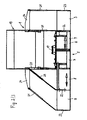
- Fig. 1 shows a side view of a paver.
- Fig. 2 shows a rear view of the paver right without and left with extended extension screed.
- Fig. 3 shows a hydraulic circuit diagram for a Stauerzylinderbeetzwegung.
- the paver shown in the non-working state for the bottom-side installation of layers of roads or the like. includes a chassis 1 with crawler tracks 2 (instead, can also be provided bogies), the chassis 1 on the front of a bucket 3 and the rear a distributor screw 4, between which a (not visible) conveyor for transporting mix to be incorporated from the bucket 3 by a Delivery shaft, over which structures are located in the area of the distributor screw 4 is arranged.
- a floating screed 5 is articulated for floating installation of Constant mix via tension arms 6.
- the screed 5 is located in the installation direction behind the area of the auger 4 and may comprise a base pile 7 and with respect to this laterally and independently extendable Ausfahrbohlen 8.
- the base screed 7 is usually divided in the middle, wherein the two halves of the base screed 7 for adjusting a roof profile via a corresponding adjusting device 17 transversely to the installation direction are mutually tilted.
- the extension boards 8 the base pile 7 is broadened to about twice its width. If no extension boards 8 are present or if an additional broadening is to be made, this is done by means of manually attachable screed parts 9.
- the extension boards 8 and the attachable screed parts 9 are generally offset by a screed depth relative to the base screed 7 in the installation direction.
- Each pull arm 6 is pivoted at its front end on the chassis 1, wherein the pivot point relative to the chassis 1 is height adjustable. This is effected, for example, that the tension arm 6 is forked at its front end, with its forked end a flat iron 10 engages and is arranged on a bearing ring of a arranged at 11 in the bifurcated end, the tensile forces receiving bearing on the flat iron 10, while an actuating cylinder 12 engages the forked end and determines the height of the articulation point with respect to the chassis 1 for the purpose of the change in thickness or leveling, whereby a positively adjusted angle of attack of the screed 5 relative to the substrate 14 is affected.
- Screed transport cylinder 13 serve to raise the screed 5 in transport position. These are in the installation case, apart from the case initially described when restarting the paver, generally in floating position.
- the base screed 7 comprises (as well as the extension boards 8) in particular at the bottom as compression tools at least one on a drive not shown up to a predeterminable stroke up and down movable, provided with a Dosageschräge tamper strip 16 and subsequently an optionally coupled with a vibration drive not shown smoothing plate 18th
- the drive of the tamper strip (s) 16 is designed in particular as an eccentric drive and with respect to the number of strokes of the tamper strip (s) 16 adjustable.
- the superstructures of the chassis 1 include a driver's cab 19 laterally provided with cylinder suspensions 20 for laterally outwardly extending hydraulic cylinders 21 on the piston side, while being hinged on outer cheeks 22 and 23, respectively, of the extension boards 8 and the staked board parts 9, respectively are.
- the articulation takes place at least for existing extension boards 8, for example, via spherical plain bearings or ball joints, which have sufficient clearance, so that the hydraulic Boom broadening by extending the extension boards 8 is not affected. Accordingly large, the stroke of the hydraulic cylinder 21 has to be so that they are fair without dismantling all screed adjustments relative to the paver.
- At least one hydraulic support cylinder 21 is arranged on each side of the paver and loaded at hydraulic loading the respective screed half substantially vertically.
- Ausfahrbohlen 8 and piezied screed parts 9 may be hinged to the latter attacking support cylinder 21 in the rear paver area laterally outwardly projecting arms 24.
- the support cylinder 21 are not blocked on the piston side in contrast to Pohlenaufsteigarret réelle by the screed transport cylinder 13 at the moment of startup, but acted upon by an adjustable hydraulic pressure.
- the cylinder suspensions 20 on the chassis 1 and on the screed 5 are suitably mounted so that the permissible transport width for the paver with retracted extension boards 8 of 2.55 m and 3 m is not exceeded.
- hydraulic pressure used for their application is preferably adjustable. It is also expedient if the control of the pressurization of the hydraulic cylinder 21 is locked to the traction drive so that it is either already effective when stopping the paver or only when starting. The duration of effectiveness can also be designed adjustable. In addition, it is expedient to synchronize the control of the pressurization with the existing in the base width screed lift arrest. Optionally, the control of the pressurization according to the need also be done manually.
- the pressurization is designed so that the floating behavior (floating) of the screed 5, ie relative movements of the screed 5 opposite the paver is maintained in the vertical direction, both on and off pressurized.
- Fig. 3 shows a hydraulic circuit for actuating the support cylinder 21.
- a motor 25 such as the diesel engine of the paver, driven hydraulic pump 26 is provided.
- the latter may be a pump which also provides for other hydraulic power units or may be a separate pump.
- the hydraulic pump 26 delivers hydraulic fluid from a reservoir 27 via a 4-2-way valve 28 to the support cylinders 21, wherein in the illustrated position of the 4-2-way valve 28, the support cylinder 21 unencumbered, ie with the reservoir 27 as well as the hydraulic pump 26th associated circle are connected.
- an electrically or manually adjustable for example, set to a maximum pressure of 50 bar pressure relief valve 29 is provided.
- the 4-2-way valve 28 is electrically controlled via the drive of the paver, so that when restarting (or even when stopping) the paver is switched, so that the support cylinders 21 are pressurized. This pressurization is maintained (not shown) via a time relay triggered by the travel drive when restarting for a predetermined, optionally adjustable time of, for example, 5 or 10 sec. Thereafter, the 4-2-way valve 28 takes in Fig. 3 shown position again, so that the support cylinder 21 are no longer pressurized.
Landscapes
- Engineering & Computer Science (AREA)
- Architecture (AREA)
- Civil Engineering (AREA)
- Structural Engineering (AREA)
- Road Paving Machines (AREA)
- Road Paving Structures (AREA)
- Body Structure For Vehicles (AREA)
Applications Claiming Priority (2)
| Application Number | Priority Date | Filing Date | Title |
|---|---|---|---|
| DE10155507A DE10155507B4 (de) | 2001-11-13 | 2001-11-13 | Fertiger zum bodenseitigen Einbau von Schichten für Straßen od. dgl. |
| DE10155507 | 2001-11-13 |
Publications (3)
| Publication Number | Publication Date |
|---|---|
| EP1310598A2 EP1310598A2 (de) | 2003-05-14 |
| EP1310598A3 EP1310598A3 (de) | 2004-03-03 |
| EP1310598B1 true EP1310598B1 (de) | 2008-07-16 |
Family
ID=7705467
Family Applications (1)
| Application Number | Title | Priority Date | Filing Date |
|---|---|---|---|
| EP02025023A Expired - Lifetime EP1310598B1 (de) | 2001-11-13 | 2002-11-11 | Fertiger zum bodenseitigen Einbau von Schichten für Strassen od. dgl. |
Country Status (10)
| Country | Link |
|---|---|
| US (1) | US6932538B2 (da) |
| EP (1) | EP1310598B1 (da) |
| JP (1) | JP3834794B2 (da) |
| CN (1) | CN1419009B (da) |
| AT (1) | ATE401458T1 (da) |
| CA (1) | CA2411602C (da) |
| DE (2) | DE10155507B4 (da) |
| DK (1) | DK1310598T3 (da) |
| ES (1) | ES2307700T3 (da) |
| RU (1) | RU2260647C2 (da) |
Families Citing this family (20)
| Publication number | Priority date | Publication date | Assignee | Title |
|---|---|---|---|---|
| US20050058507A1 (en) * | 2003-09-17 | 2005-03-17 | Cedarapids, Inc. | Multi-use paving tractor with tool attachments |
| US20070065230A1 (en) * | 2003-09-17 | 2007-03-22 | Cedarapids, Inc. | Self Propelled Remix Machine with Conveyor |
| US7458747B2 (en) * | 2003-09-17 | 2008-12-02 | Cedarapids, Inc. | Frame raising multi-use paving tractor with blind mateable quick connecting tool attachments |
| US7198429B2 (en) * | 2004-03-31 | 2007-04-03 | Fabcon, Inc. | Segmented concrete screed |
| CA2582210A1 (en) * | 2006-03-22 | 2007-09-22 | Cedarapids, Inc. | Multi-stage modular road paving equipment and method of manufacture and sales |
| EP2218824B1 (de) * | 2009-02-16 | 2012-12-26 | Joseph Vögele AG | Einbaubohle |
| DE102009019839A1 (de) † | 2009-03-09 | 2010-09-16 | Bomag Gmbh | Hydraulische Steueranordnung für die Bohle eines Straßenfertigers |
| PL2256247T5 (pl) * | 2009-05-25 | 2018-02-28 | Joseph Vögele AG | Wykańczarka |
| DE502009000291D1 (de) * | 2009-05-25 | 2011-02-24 | Joseph Voegele Ag | Straßenfertiger und Verfahren |
| JP5089670B2 (ja) * | 2009-10-16 | 2012-12-05 | 住友建機株式会社 | 舗装機械におけるスクリード伸縮装置 |
| EP2325392B1 (de) * | 2009-11-20 | 2020-09-30 | Joseph Vögele AG | Verfahren zum einbauen eines belages, einbaubohle und strassenfertiger |
| DE202010012456U1 (de) * | 2010-09-10 | 2011-12-12 | Smg Sportplatzmaschinenbau Gmbh | Einbaufertiger mit einem Vorratsbehälter |
| US8529152B1 (en) * | 2012-03-28 | 2013-09-10 | Caterpillar Paving Products Inc. | Resistive braking via screed heating |
| DE102012206857A1 (de) * | 2012-04-25 | 2013-10-31 | Leonhard Weiss Gmbh & Co. Kg | Sperrbare Bohlenspannvorrichtung |
| CN102720117B (zh) * | 2012-06-27 | 2015-01-07 | 中联重科股份有限公司 | 熨平板和摊铺机 |
| CN102852078A (zh) * | 2012-08-18 | 2013-01-02 | 徐州凯莫尔重工科技有限公司 | 一种伸缩熨平板前拉伸油缸固定机构 |
| US9200415B2 (en) * | 2013-11-19 | 2015-12-01 | Caterpillar Paving Products Inc. | Paving machine with automatically adjustable screed assembly |
| US10472777B1 (en) * | 2018-05-02 | 2019-11-12 | Caterpillar Paving Products Inc. | Screed tow point assembly for paver |
| CN111648211A (zh) * | 2020-06-10 | 2020-09-11 | 陕西建设机械股份有限公司 | 一种伸缩熨平板加长支撑装置及施工方法 |
| CN113152222B (zh) * | 2021-04-13 | 2022-11-29 | 徐州工业职业技术学院 | 一种适用于小型摊铺机的熨平板 |
Family Cites Families (15)
| Publication number | Priority date | Publication date | Assignee | Title |
|---|---|---|---|---|
| FR1337936A (fr) * | 1962-08-27 | 1963-09-20 | Jaeger Machine Co | Machine de nivellement et de répartition de matériaux pour l'élargissement de routes |
| US3891338A (en) * | 1973-04-30 | 1975-06-24 | Barber Greene Co | Convergent link system for connecting a screed to the traction unit of a paving machine |
| DE2543104C3 (de) * | 1975-09-25 | 1979-05-31 | Ernst-August 4450 Lingen Schrader | Vorrichtung zur stufenlosen Verstellung der Arbeitsbreiten von Straßenfertigern |
| US4147448A (en) * | 1977-05-25 | 1979-04-03 | The South African Inventions Development Corporation | Method of operating a compaction roller assembly, and a compaction roller assembly |
| CH657168A5 (it) * | 1982-11-16 | 1986-08-15 | Domenico Domenighetti | Finitrice di manto stradale con rasatore munito di elementi laterali estensibili che consentono l'allargamento del manto da stendere sul terreno. |
| DE3535362C1 (de) * | 1985-10-03 | 1987-03-26 | Joseph Voegele Ag | Verfahren und Vorrichtung zur Hoehenregulierung einer Nivellierungsbohle |
| DE4211286C2 (de) * | 1992-04-03 | 2003-08-21 | Metso Dynapac Gmbh | Verfahren zum Arretieren einer Einbausohle eines Straßenfertigers und Straßenfertiger zur Durchführung des Verfahrens |
| RU2077635C1 (ru) * | 1994-03-16 | 1997-04-20 | Егор Викторович Самуйлов | Асфальтоукладчик |
| DE9406683U1 (de) * | 1994-04-21 | 1994-06-30 | Joseph Vögele AG, 68163 Mannheim | Straßenfertiger |
| IT1276147B1 (it) * | 1995-11-16 | 1997-10-27 | Niarb S A | Finitrice stradale con controllo automatico dell'altezza delle coclee trasversali rispetto al rasatore |
| DE19605148C1 (de) * | 1996-02-13 | 1997-07-31 | Abg Allg Baumaschinen Gmbh | Straßenfertiger |
| DE19739687C1 (de) * | 1997-09-10 | 1999-04-08 | Abg Allg Baumaschinen Gmbh | Straßenfertiger |
| DE19833394C1 (de) * | 1998-07-24 | 1999-09-30 | Abg Allg Baumaschinen Gmbh | Einbaubohle für einen Straßenfertiger |
| EP1120495A1 (de) * | 2000-01-25 | 2001-08-01 | Joseph Vögele AG | Strassenfertiger |
| DE10036784C1 (de) * | 2000-07-28 | 2001-09-20 | Abg Allg Baumaschinen Gmbh | Einbaubohle für einen Straßenfertiger |
-
2001
- 2001-11-13 DE DE10155507A patent/DE10155507B4/de not_active Expired - Lifetime
-
2002
- 2002-11-08 CN CN021503826A patent/CN1419009B/zh not_active Expired - Lifetime
- 2002-11-11 AT AT02025023T patent/ATE401458T1/de active
- 2002-11-11 ES ES02025023T patent/ES2307700T3/es not_active Expired - Lifetime
- 2002-11-11 EP EP02025023A patent/EP1310598B1/de not_active Expired - Lifetime
- 2002-11-11 DE DE50212500T patent/DE50212500D1/de not_active Expired - Lifetime
- 2002-11-11 DK DK02025023T patent/DK1310598T3/da active
- 2002-11-12 RU RU2002130442/03A patent/RU2260647C2/ru not_active IP Right Cessation
- 2002-11-12 US US10/292,049 patent/US6932538B2/en not_active Expired - Lifetime
- 2002-11-12 CA CA002411602A patent/CA2411602C/en not_active Expired - Fee Related
- 2002-11-13 JP JP2002329155A patent/JP3834794B2/ja not_active Expired - Fee Related
Also Published As
| Publication number | Publication date |
|---|---|
| CN1419009A (zh) | 2003-05-21 |
| DE10155507B4 (de) | 2005-10-06 |
| EP1310598A3 (de) | 2004-03-03 |
| US20030113166A1 (en) | 2003-06-19 |
| JP3834794B2 (ja) | 2006-10-18 |
| JP2003184024A (ja) | 2003-07-03 |
| DK1310598T3 (da) | 2008-11-10 |
| RU2260647C2 (ru) | 2005-09-20 |
| CA2411602C (en) | 2007-01-23 |
| CN1419009B (zh) | 2011-10-26 |
| ATE401458T1 (de) | 2008-08-15 |
| CA2411602A1 (en) | 2003-05-13 |
| ES2307700T3 (es) | 2008-12-01 |
| EP1310598A2 (de) | 2003-05-14 |
| DE50212500D1 (de) | 2008-08-28 |
| US6932538B2 (en) | 2005-08-23 |
| DE10155507A1 (de) | 2003-05-28 |
Similar Documents
| Publication | Publication Date | Title |
|---|---|---|
| EP1310598B1 (de) | Fertiger zum bodenseitigen Einbau von Schichten für Strassen od. dgl. | |
| DE19836269C1 (de) | Straßenfertiger | |
| EP2238071B1 (de) | Fahrbare arbeitsmaschine | |
| DE102015006250A1 (de) | Anbaubohleneinheit für einen Straßenfertiger und Straßenfertiger mit einer solchen Anbaubohleneinheit | |
| DE102017009249B4 (de) | Kleinfertiger sowie Verfahren zum Betrieb eines Kleinfertigers | |
| WO2018033516A1 (de) | Böschungsfertiger | |
| EP3498916B1 (de) | Strassenfertiger mit schwenkbarem materialabweiser | |
| EP3793929B1 (de) | Fahrzeugkran mit einem beweglichen adapter zwischen hauptausleger und hauptauslegerverlängerung | |
| DE8300083U1 (de) | Einbaubohle fuer einen strassenfertiger | |
| DE3016232A1 (de) | Selbstfahrende betonpumpe | |
| EP1582629A1 (de) | Fertiger und Verfahren zum gleichzeitigen Einbauen mehrerer Einbaugut-Lagen | |
| EP0663478B1 (de) | Kombination eines Baggers mit einer Rütteleinrichtung | |
| EP0901541B1 (de) | Verdichtungsvorrichtung | |
| LU502197B1 (en) | Bauverfahren zum Gießen von hochfestem und wasserundurchlässigem Beton sowie Vorrichtung desselben | |
| EP0335339B1 (de) | Tragschichtfertiger | |
| DE102013103642B4 (de) | Planiervorrichtung | |
| DE20000148U1 (de) | Fertiger im Containermaß | |
| EP3135815A1 (de) | Einbaubohle für einen strassenfertiger | |
| DE60020180T2 (de) | Vibrierende Strassendeckenfertiger für Asphalt | |
| DE102005019139B4 (de) | Einbaubohle mit vorgelagerter Verdichtungseinheit | |
| DE4229464A1 (de) | Schwarzdeckenfertiger mit ausziehbarer Glättbohle | |
| DE202014004264U1 (de) | Planiervorrichtung | |
| EP0513942B1 (de) | Aushebeeinrichtung für einen Strassenfertiger | |
| DE2333371A1 (de) | Glaettbohle fuer einen strassenfertiger | |
| EP1972721A2 (de) | Arbeitsmaschineneinheit, insbesondere zum Einbau und zum Verdichten von Straßenbelagsschichten, sowie Verfahren zur Montage der Arbeitsmaschineneinheit |
Legal Events
| Date | Code | Title | Description |
|---|---|---|---|
| PUAI | Public reference made under article 153(3) epc to a published international application that has entered the european phase |
Free format text: ORIGINAL CODE: 0009012 |
|
| AK | Designated contracting states |
Designated state(s): AT BE BG CH CY CZ DE DK EE ES FI FR GB GR IE IT LI LU MC NL PT SE SK TR |
|
| AX | Request for extension of the european patent |
Extension state: AL LT LV MK RO SI |
|
| PUAL | Search report despatched |
Free format text: ORIGINAL CODE: 0009013 |
|
| AK | Designated contracting states |
Kind code of ref document: A3 Designated state(s): AT BE BG CH CY CZ DE DK EE ES FI FR GB GR IE IT LI LU MC NL PT SE SK TR |
|
| AX | Request for extension of the european patent |
Extension state: AL LT LV MK RO SI |
|
| 17P | Request for examination filed |
Effective date: 20040629 |
|
| AKX | Designation fees paid |
Designated state(s): AT BE BG CH CY CZ DE DK EE ES FI FR GB GR IE IT LI LU MC NL PT SE SK TR |
|
| 17Q | First examination report despatched |
Effective date: 20070530 |
|
| GRAP | Despatch of communication of intention to grant a patent |
Free format text: ORIGINAL CODE: EPIDOSNIGR1 |
|
| GRAS | Grant fee paid |
Free format text: ORIGINAL CODE: EPIDOSNIGR3 |
|
| GRAA | (expected) grant |
Free format text: ORIGINAL CODE: 0009210 |
|
| AK | Designated contracting states |
Kind code of ref document: B1 Designated state(s): AT BE BG CH CY CZ DE DK EE ES FI FR GB GR IE IT LI LU MC NL PT SE SK TR |
|
| REG | Reference to a national code |
Ref country code: GB Ref legal event code: FG4D Free format text: NOT ENGLISH |
|
| REG | Reference to a national code |
Ref country code: CH Ref legal event code: EP |
|
| REG | Reference to a national code |
Ref country code: CH Ref legal event code: NV Representative=s name: DR. LUSUARDI AG |
|
| REF | Corresponds to: |
Ref document number: 50212500 Country of ref document: DE Date of ref document: 20080828 Kind code of ref document: P |
|
| REG | Reference to a national code |
Ref country code: IE Ref legal event code: FG4D Free format text: LANGUAGE OF EP DOCUMENT: GERMAN |
|
| REG | Reference to a national code |
Ref country code: DK Ref legal event code: T3 |
|
| REG | Reference to a national code |
Ref country code: ES Ref legal event code: FG2A Ref document number: 2307700 Country of ref document: ES Kind code of ref document: T3 |
|
| PG25 | Lapsed in a contracting state [announced via postgrant information from national office to epo] |
Ref country code: PT Free format text: LAPSE BECAUSE OF FAILURE TO SUBMIT A TRANSLATION OF THE DESCRIPTION OR TO PAY THE FEE WITHIN THE PRESCRIBED TIME-LIMIT Effective date: 20081216 |
|
| PG25 | Lapsed in a contracting state [announced via postgrant information from national office to epo] |
Ref country code: BG Free format text: LAPSE BECAUSE OF FAILURE TO SUBMIT A TRANSLATION OF THE DESCRIPTION OR TO PAY THE FEE WITHIN THE PRESCRIBED TIME-LIMIT Effective date: 20081016 Ref country code: FI Free format text: LAPSE BECAUSE OF FAILURE TO SUBMIT A TRANSLATION OF THE DESCRIPTION OR TO PAY THE FEE WITHIN THE PRESCRIBED TIME-LIMIT Effective date: 20080716 |
|
| REG | Reference to a national code |
Ref country code: IE Ref legal event code: FD4D |
|
| PG25 | Lapsed in a contracting state [announced via postgrant information from national office to epo] |
Ref country code: IE Free format text: LAPSE BECAUSE OF FAILURE TO SUBMIT A TRANSLATION OF THE DESCRIPTION OR TO PAY THE FEE WITHIN THE PRESCRIBED TIME-LIMIT Effective date: 20080716 Ref country code: EE Free format text: LAPSE BECAUSE OF FAILURE TO SUBMIT A TRANSLATION OF THE DESCRIPTION OR TO PAY THE FEE WITHIN THE PRESCRIBED TIME-LIMIT Effective date: 20080716 |
|
| PLBE | No opposition filed within time limit |
Free format text: ORIGINAL CODE: 0009261 |
|
| STAA | Information on the status of an ep patent application or granted ep patent |
Free format text: STATUS: NO OPPOSITION FILED WITHIN TIME LIMIT |
|
| PG25 | Lapsed in a contracting state [announced via postgrant information from national office to epo] |
Ref country code: CZ Free format text: LAPSE BECAUSE OF FAILURE TO SUBMIT A TRANSLATION OF THE DESCRIPTION OR TO PAY THE FEE WITHIN THE PRESCRIBED TIME-LIMIT Effective date: 20080716 Ref country code: SK Free format text: LAPSE BECAUSE OF FAILURE TO SUBMIT A TRANSLATION OF THE DESCRIPTION OR TO PAY THE FEE WITHIN THE PRESCRIBED TIME-LIMIT Effective date: 20080716 |
|
| BERE | Be: lapsed |
Owner name: ABG ALLGEMEINE BAUMASCHINEN-GESELLSCHAFT MBH Effective date: 20081130 |
|
| 26N | No opposition filed |
Effective date: 20090417 |
|
| PG25 | Lapsed in a contracting state [announced via postgrant information from national office to epo] |
Ref country code: MC Free format text: LAPSE BECAUSE OF NON-PAYMENT OF DUE FEES Effective date: 20081130 |
|
| PG25 | Lapsed in a contracting state [announced via postgrant information from national office to epo] |
Ref country code: BE Free format text: LAPSE BECAUSE OF NON-PAYMENT OF DUE FEES Effective date: 20081130 |
|
| PG25 | Lapsed in a contracting state [announced via postgrant information from national office to epo] |
Ref country code: SE Free format text: LAPSE BECAUSE OF FAILURE TO SUBMIT A TRANSLATION OF THE DESCRIPTION OR TO PAY THE FEE WITHIN THE PRESCRIBED TIME-LIMIT Effective date: 20081016 |
|
| PG25 | Lapsed in a contracting state [announced via postgrant information from national office to epo] |
Ref country code: LU Free format text: LAPSE BECAUSE OF NON-PAYMENT OF DUE FEES Effective date: 20081111 Ref country code: CY Free format text: LAPSE BECAUSE OF FAILURE TO SUBMIT A TRANSLATION OF THE DESCRIPTION OR TO PAY THE FEE WITHIN THE PRESCRIBED TIME-LIMIT Effective date: 20080716 |
|
| PG25 | Lapsed in a contracting state [announced via postgrant information from national office to epo] |
Ref country code: TR Free format text: LAPSE BECAUSE OF FAILURE TO SUBMIT A TRANSLATION OF THE DESCRIPTION OR TO PAY THE FEE WITHIN THE PRESCRIBED TIME-LIMIT Effective date: 20080716 |
|
| PG25 | Lapsed in a contracting state [announced via postgrant information from national office to epo] |
Ref country code: GR Free format text: LAPSE BECAUSE OF FAILURE TO SUBMIT A TRANSLATION OF THE DESCRIPTION OR TO PAY THE FEE WITHIN THE PRESCRIBED TIME-LIMIT Effective date: 20081017 |
|
| REG | Reference to a national code |
Ref country code: FR Ref legal event code: PLFP Year of fee payment: 14 |
|
| PGFP | Annual fee paid to national office [announced via postgrant information from national office to epo] |
Ref country code: DK Payment date: 20151112 Year of fee payment: 14 |
|
| PGFP | Annual fee paid to national office [announced via postgrant information from national office to epo] |
Ref country code: NL Payment date: 20151113 Year of fee payment: 14 Ref country code: AT Payment date: 20151111 Year of fee payment: 14 |
|
| REG | Reference to a national code |
Ref country code: FR Ref legal event code: PLFP Year of fee payment: 15 |
|
| REG | Reference to a national code |
Ref country code: DK Ref legal event code: EBP Effective date: 20161130 |
|
| REG | Reference to a national code |
Ref country code: NL Ref legal event code: MM Effective date: 20161201 |
|
| REG | Reference to a national code |
Ref country code: AT Ref legal event code: MM01 Ref document number: 401458 Country of ref document: AT Kind code of ref document: T Effective date: 20161111 |
|
| PG25 | Lapsed in a contracting state [announced via postgrant information from national office to epo] |
Ref country code: AT Free format text: LAPSE BECAUSE OF NON-PAYMENT OF DUE FEES Effective date: 20161111 |
|
| PG25 | Lapsed in a contracting state [announced via postgrant information from national office to epo] |
Ref country code: NL Free format text: LAPSE BECAUSE OF NON-PAYMENT OF DUE FEES Effective date: 20161201 |
|
| REG | Reference to a national code |
Ref country code: FR Ref legal event code: PLFP Year of fee payment: 16 |
|
| PG25 | Lapsed in a contracting state [announced via postgrant information from national office to epo] |
Ref country code: DK Free format text: LAPSE BECAUSE OF NON-PAYMENT OF DUE FEES Effective date: 20161130 |
|
| PGFP | Annual fee paid to national office [announced via postgrant information from national office to epo] |
Ref country code: CH Payment date: 20171115 Year of fee payment: 16 Ref country code: ES Payment date: 20171218 Year of fee payment: 16 Ref country code: IT Payment date: 20171120 Year of fee payment: 16 |
|
| REG | Reference to a national code |
Ref country code: CH Ref legal event code: PL |
|
| PG25 | Lapsed in a contracting state [announced via postgrant information from national office to epo] |
Ref country code: LI Free format text: LAPSE BECAUSE OF NON-PAYMENT OF DUE FEES Effective date: 20181130 Ref country code: CH Free format text: LAPSE BECAUSE OF NON-PAYMENT OF DUE FEES Effective date: 20181130 |
|
| PG25 | Lapsed in a contracting state [announced via postgrant information from national office to epo] |
Ref country code: IT Free format text: LAPSE BECAUSE OF NON-PAYMENT OF DUE FEES Effective date: 20181111 |
|
| REG | Reference to a national code |
Ref country code: ES Ref legal event code: FD2A Effective date: 20200102 |
|
| PG25 | Lapsed in a contracting state [announced via postgrant information from national office to epo] |
Ref country code: ES Free format text: LAPSE BECAUSE OF NON-PAYMENT OF DUE FEES Effective date: 20181112 |
|
| PGFP | Annual fee paid to national office [announced via postgrant information from national office to epo] |
Ref country code: DE Payment date: 20211129 Year of fee payment: 20 Ref country code: GB Payment date: 20211123 Year of fee payment: 20 Ref country code: FR Payment date: 20211126 Year of fee payment: 20 |
|
| REG | Reference to a national code |
Ref country code: DE Ref legal event code: R071 Ref document number: 50212500 Country of ref document: DE |
|
| REG | Reference to a national code |
Ref country code: GB Ref legal event code: PE20 Expiry date: 20221110 |
|
| PG25 | Lapsed in a contracting state [announced via postgrant information from national office to epo] |
Ref country code: GB Free format text: LAPSE BECAUSE OF EXPIRATION OF PROTECTION Effective date: 20221110 |