EP1310603A1 - Mechanismus zum vollen oder teilweisen entleeren des toilettenspülkastens - Google Patents
Mechanismus zum vollen oder teilweisen entleeren des toilettenspülkastens Download PDFInfo
- Publication number
- EP1310603A1 EP1310603A1 EP01951711A EP01951711A EP1310603A1 EP 1310603 A1 EP1310603 A1 EP 1310603A1 EP 01951711 A EP01951711 A EP 01951711A EP 01951711 A EP01951711 A EP 01951711A EP 1310603 A1 EP1310603 A1 EP 1310603A1
- Authority
- EP
- European Patent Office
- Prior art keywords
- overflow pipe
- discharge
- overflow
- floats
- crosspiece
- Prior art date
- Legal status (The legal status is an assumption and is not a legal conclusion. Google has not performed a legal analysis and makes no representation as to the accuracy of the status listed.)
- Withdrawn
Links
- 230000007246 mechanism Effects 0.000 title claims abstract description 19
- 238000011010 flushing procedure Methods 0.000 title abstract 2
- 230000037431 insertion Effects 0.000 claims description 4
- 238000003780 insertion Methods 0.000 claims description 4
- 230000002787 reinforcement Effects 0.000 claims description 4
- XLYOFNOQVPJJNP-UHFFFAOYSA-N water Substances O XLYOFNOQVPJJNP-UHFFFAOYSA-N 0.000 claims description 3
- 230000006872 improvement Effects 0.000 abstract description 3
- 238000004519 manufacturing process Methods 0.000 abstract 1
- 230000001105 regulatory effect Effects 0.000 abstract 1
- 230000008878 coupling Effects 0.000 description 3
- 238000010168 coupling process Methods 0.000 description 3
- 238000005859 coupling reaction Methods 0.000 description 3
- 230000009471 action Effects 0.000 description 1
- 230000003213 activating effect Effects 0.000 description 1
- 230000004913 activation Effects 0.000 description 1
- 238000006073 displacement reaction Methods 0.000 description 1
- 230000000694 effects Effects 0.000 description 1
- 238000009434 installation Methods 0.000 description 1
Images




Classifications
-
- E—FIXED CONSTRUCTIONS
- E03—WATER SUPPLY; SEWERAGE
- E03D—WATER-CLOSETS OR URINALS WITH FLUSHING DEVICES; FLUSHING VALVES THEREFOR
- E03D1/00—Water flushing devices with cisterns ; Setting up a range of flushing devices or water-closets; Combinations of several flushing devices
- E03D1/02—High-level flushing systems
- E03D1/14—Cisterns discharging variable quantities of water also cisterns with bell siphons in combination with flushing valves
- E03D1/142—Cisterns discharging variable quantities of water also cisterns with bell siphons in combination with flushing valves in cisterns with flushing valves
- E03D1/144—Cisterns discharging variable quantities of water also cisterns with bell siphons in combination with flushing valves in cisterns with flushing valves having a single flush outlet and an additional float for delaying the valve closure
Definitions
- Discharge devices operated to cause the discharge are already known, there also being double discharge devices. There are some of these on the market with a double cistern, one larger and one smaller one, which selectively discharge one amount of water or another.
- the applicant of this patent also has ES P9302624 for a discharge device for cisterns with discharge interruption, consisting of an assembly fitted with a double valve with arms which, when the discharge mechanism is activated again, interrupt this.
- the object of this invention is a mechanism for full or selective discharge in toilet cisterns, which includes improvements as regards the discharge-activating device.
- a gate is thus held by two buoys at different heights, both of these having an identical layout, and being set up in such a way that during the discharge they hold the pipe connected to the gate which is lifted during the discharge, until the discharge volume required is reached. After reaching this discharge level, the pipe and the gate fall, interrupting the discharge in the case of partial discharge and in the other case, completely emptying the cistern.
- the buoys, the way these retain the discharge pipe in respect of the hood and also the means for pulling the activating device both in the single discharge and in the double discharge operations all involve specific characteristics.
- the pressing mechanism consists of a mechanism fitted with a single activation shaft but which, through the pressing movement and corresponding lever, pulls the overflow pipe to one extent or another.
- the buoys swing and lock and later free the overflow pipe.
- the pressing device has a double configuration. Pressing the larger section causes a larger, full discharge. Pressing the smaller section causes a lesser, partial discharge.
- the hood houses the buoys and their axes occupy a chord of the circumference defined by its perimeter. Both buoys preferably but not only take opposite positions, symmetrical at different heights, with parallel axes; and located by said position each on one side of the overflow pipe. They can nevertheless be parallel and occupy the same position at different heights.
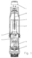
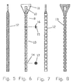
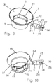
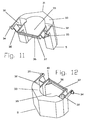
- 1 represents the pressing mechanism casing, for operating the discharge; 2 the annulated overflow pipe; 3 the hood; 4 the upper float; 5 the lower float; 6 the gate; 7 the overflow pipe; 8 the regulation rod; 9 the overflow arm 7; 10 the regulation rod insertion hole 11, over the discharge lever; 11 the head of the regulation rod; 12 the section of the wide part of the rod 8; 13 the section of the stepped part of the rod 8; 14 the cylindrical portion of the rod 8; 15 the shape of the cutaway in the stepped part of the rod 8; 16 the outer track of the rod, according to the external part of section 12; 17 the section of portion 14; 18 the tapering portion of the overflow pipe 7; 19 the cylindrical portion of the overflow pipe 7; 20 the notch for supporting the edge of the overflow pipe or insertion limit of this pipe; 21 the interior recess, or expansion of the internal diameter; 22 the lug at the base of the recess; 23 the coupling of the arm 9 to the tapering cone 18; 24 the reinforcement of the coupling 23; 25 the external
- the discharge mechanism is operated by pulling the overflow pipe by means of the puller 45.
- the length of the overflow pipe 5 depends on the capacity and geometry of the cistern. For the installation of the device the surplus part of the pipe over the ideal level of the cistern must thus be eliminated.
- the pulling takes place in this embodiment from the annular body arranged as an overflow 7 and inserted by elastic pressure, from which an arm 9 comes out perpendicularly.
- This arm has a "U" shape at the end 25.
- This "U” is inserted in the corresponding position to the length of the pipe depending on the geometry of the cistern after having cut off the unwanted part of pipe 2.
- the engagement or securing takes place by the insertion of the "U” 25 in any position of the rod.
- the rod has a stepped section 13 able to allow the engagement of the arm being inserted in the hollow 28 after being inserted through mouth 26 and overcoming the interior projections 27 by elasticity.
- the arm is reduced with the upper recess 29 and lower recess 30 to facilitate greater thickness and resistance of its body, and let the rod in to the selected position.
- the device for retaining the overflow pipe during discharge consists of floats 5 which in combination with said pipe 2, produce the effect of retaining or releasing the overflow pipe which has the gate at the bottom.
- the structure which determines how this operates can be appreciated in figures 1 and 2.
- the hood 3 has holes corresponding to the spindle pins of the floats, whose unification determines a chord of the circumference located at the opposite end of the pipe 2 to the one occupied by each float.
- the floats 4 and 5 have the aforementioned pins able to be inserted in these holes.
- the spindle of the float determines a coupling according to said chord. When this is located in the eccentric position, the dry float tends to drop, swinging in respect of its spindles. When the cistern is filled with water, the floatability of its floating vessel keeps this in a horizontal position.
- the step 37 of the crosspiece 36 of the floats releases or retains the steps 42 and 43 of this pipe 2 and thus retains or stops the corresponding discharge section.
- This device is for industrial application in making discharge devices for toilet cisterns.
Landscapes
- Health & Medical Sciences (AREA)
- Life Sciences & Earth Sciences (AREA)
- Engineering & Computer Science (AREA)
- Hydrology & Water Resources (AREA)
- Public Health (AREA)
- Water Supply & Treatment (AREA)
- Bidet-Like Cleaning Device And Other Flush Toilet Accessories (AREA)
- Sanitary Device For Flush Toilet (AREA)
Applications Claiming Priority (3)
| Application Number | Priority Date | Filing Date | Title |
|---|---|---|---|
| ES200002034 | 2000-08-09 | ||
| ES200002034A ES2187247B1 (es) | 1998-01-29 | 2000-08-09 | Primer certificado de adicion a la patente principal n. p9800161 por mecanismo para la descarga total o selectiva en cisternas de inodoro. |
| PCT/ES2001/000289 WO2002012645A1 (es) | 2000-08-09 | 2001-07-20 | Mecanismo para la descarga total o selectiva en cisternas de inodoro |
Publications (1)
| Publication Number | Publication Date |
|---|---|
| EP1310603A1 true EP1310603A1 (de) | 2003-05-14 |
Family
ID=8494651
Family Applications (1)
| Application Number | Title | Priority Date | Filing Date |
|---|---|---|---|
| EP01951711A Withdrawn EP1310603A1 (de) | 2000-08-09 | 2001-07-20 | Mechanismus zum vollen oder teilweisen entleeren des toilettenspülkastens |
Country Status (4)
| Country | Link |
|---|---|
| EP (1) | EP1310603A1 (de) |
| AR (1) | AR031258A1 (de) |
| AU (1) | AU2001272567A1 (de) |
| WO (1) | WO2002012645A1 (de) |
Cited By (10)
| Publication number | Priority date | Publication date | Assignee | Title |
|---|---|---|---|---|
| WO2004070124A1 (es) * | 2003-02-06 | 2004-08-19 | Fominaya, S.A. | Perfeccionamientos en descargadores de cisternas inodoros |
| WO2006068628A1 (en) * | 2004-12-20 | 2006-06-29 | Eczacibasi Yapi Gerecleri Sanayi Ve Ticaret A.S. | Dual volume flush system |
| EP1674623A3 (de) * | 2004-12-24 | 2006-11-02 | Oliveira & Irmao S.A. | Ablaufventil für einen Spülkasten |
| EP1795660A3 (de) * | 2005-12-09 | 2007-12-12 | Oliveira & Irmao S.A. | Ablaufventilanordnung für einen Spülkasten |
| EP1795661A3 (de) * | 2005-12-09 | 2007-12-19 | Oliveira & Irmao S.A. | Entleerungsventilanordnung für einen Spülkasten mit einem System zur Regelung der zu entleerenden Wassermenge |
| WO2008041057A1 (en) * | 2006-10-03 | 2008-04-10 | Eczacibasi Yapi Gereçleri Sanayi Ve Ticaret A.S. | Dual volume flush system |
| DE102007001718A1 (de) * | 2006-11-03 | 2008-05-08 | Tece Gmbh | Ablaufventil mit einstellbarer Vollspülmenge |
| DE102006051823A1 (de) * | 2006-11-03 | 2008-05-08 | Tece Gmbh | Zwei-Mengen-Ablaufventil |
| EP2098649A2 (de) | 2008-03-07 | 2009-09-09 | Kolektor Liv Predelava Plastike D.o.o. | Ablaufventil, das eine Wahl der Spülwassermenge in einem Spülkasten zulässt |
| WO2017098067A1 (es) * | 2015-12-10 | 2017-06-15 | Fominaya, S.A. | Dispositivo para la regulación en altura de un descargador de cisternas |
Families Citing this family (3)
| Publication number | Priority date | Publication date | Assignee | Title |
|---|---|---|---|---|
| ES2188414B1 (es) * | 2001-11-21 | 2004-08-16 | Idrols, S.A. | Conjunto de tubo rebosadero para descargador de cisternas de inodoro. |
| ES2224793B1 (es) * | 2002-07-02 | 2005-12-01 | Idrols, S.A. | Descargador de accionamiento neumatico. |
| ES2204298B1 (es) * | 2002-07-16 | 2005-06-01 | Jose Blanco Gutierrez | Dispositivo de ahorro cuantificado de agua en inodoros por doble descarga controlado por un solo pulsador. |
Family Cites Families (5)
| Publication number | Priority date | Publication date | Assignee | Title |
|---|---|---|---|---|
| ES1018394Y (es) * | 1991-08-13 | 1992-07-16 | Idrols, S.A. | Dispositivo regulador de longitud para tiradores de cisternas de sanitarios |
| FR2720421B1 (fr) * | 1994-05-30 | 1996-06-28 | Siamp Cedap Reunies | Dispositif de chasse d'eau à double bouton de commande permettant de délivrer par actionnement de chaque commande un volume de chasse prédéterminé. |
| NL1001567C1 (nl) * | 1995-02-17 | 1996-08-22 | Wisa Bv | Dubbelwerkende spoelinrichting. |
| ES1037249Y (es) * | 1997-05-13 | 1998-06-16 | Roca Radiadores | Dispositivo de descarga para cisternas de inodoros. |
| US6081938A (en) * | 1998-09-14 | 2000-07-04 | Fluidmaster, Inc. | Dual-flush valve |
-
2001
- 2001-07-20 WO PCT/ES2001/000289 patent/WO2002012645A1/es not_active Ceased
- 2001-07-20 EP EP01951711A patent/EP1310603A1/de not_active Withdrawn
- 2001-07-20 AU AU2001272567A patent/AU2001272567A1/en not_active Abandoned
- 2001-08-09 AR ARP010103807A patent/AR031258A1/es unknown
Non-Patent Citations (1)
| Title |
|---|
| See references of WO0212645A1 * |
Cited By (14)
| Publication number | Priority date | Publication date | Assignee | Title |
|---|---|---|---|---|
| WO2004070124A1 (es) * | 2003-02-06 | 2004-08-19 | Fominaya, S.A. | Perfeccionamientos en descargadores de cisternas inodoros |
| WO2006068628A1 (en) * | 2004-12-20 | 2006-06-29 | Eczacibasi Yapi Gerecleri Sanayi Ve Ticaret A.S. | Dual volume flush system |
| RU2388872C2 (ru) * | 2004-12-24 | 2010-05-10 | Оливейра Энд Ирмау, С.А. | Промывочный клапан в сборе для смывного бачка |
| EP1674623A3 (de) * | 2004-12-24 | 2006-11-02 | Oliveira & Irmao S.A. | Ablaufventil für einen Spülkasten |
| EP1795660A3 (de) * | 2005-12-09 | 2007-12-12 | Oliveira & Irmao S.A. | Ablaufventilanordnung für einen Spülkasten |
| EP1795661A3 (de) * | 2005-12-09 | 2007-12-19 | Oliveira & Irmao S.A. | Entleerungsventilanordnung für einen Spülkasten mit einem System zur Regelung der zu entleerenden Wassermenge |
| WO2008041057A1 (en) * | 2006-10-03 | 2008-04-10 | Eczacibasi Yapi Gereçleri Sanayi Ve Ticaret A.S. | Dual volume flush system |
| EA014601B1 (ru) * | 2006-10-03 | 2010-12-30 | Экзакибаси Япи Гереклери Санайи Ве Тикарет А. С. | Спускное устройство со спуском двух объёмов воды |
| DE102007001718A1 (de) * | 2006-11-03 | 2008-05-08 | Tece Gmbh | Ablaufventil mit einstellbarer Vollspülmenge |
| DE102006051823A1 (de) * | 2006-11-03 | 2008-05-08 | Tece Gmbh | Zwei-Mengen-Ablaufventil |
| DE102007001718B4 (de) | 2006-11-03 | 2022-09-08 | Tece Gmbh | Ablaufventil mit einstellbarer Vollspülmenge |
| EP2098649A2 (de) | 2008-03-07 | 2009-09-09 | Kolektor Liv Predelava Plastike D.o.o. | Ablaufventil, das eine Wahl der Spülwassermenge in einem Spülkasten zulässt |
| EP2098649A3 (de) * | 2008-03-07 | 2013-09-18 | Kolektor Liv Predelava Plastike D.o.o. | Ablaufventil, das eine Wahl der Spülwassermenge in einem Spülkasten zulässt |
| WO2017098067A1 (es) * | 2015-12-10 | 2017-06-15 | Fominaya, S.A. | Dispositivo para la regulación en altura de un descargador de cisternas |
Also Published As
| Publication number | Publication date |
|---|---|
| AR031258A1 (es) | 2003-09-17 |
| AU2001272567A1 (en) | 2002-02-18 |
| WO2002012645A1 (es) | 2002-02-14 |
Similar Documents
| Publication | Publication Date | Title |
|---|---|---|
| US4748699A (en) | Water closet limited flush volume control system | |
| US4406024A (en) | Flushing controller for toilet | |
| US3775778A (en) | Toilet flush tank mechanism | |
| US2001390A (en) | Flushing valve mechanism | |
| US3768103A (en) | Toilet tank flush valve assembly | |
| US20090126094A1 (en) | User-controlled water saving toilet | |
| US3839747A (en) | Dual flush toilet mechanism | |
| US4945580A (en) | Volume-selective water closet flushing system | |
| US4937894A (en) | Dual flush toilet | |
| AU2003236495A1 (en) | Dual capacity flush valve assembly for a toilet | |
| US4593419A (en) | Flush valve control for water closet | |
| CA2376839C (en) | Flapper valve with dual action arm | |
| US6775859B1 (en) | Dual flush toilet | |
| US6092245A (en) | Toilet operating lever for multiple applications | |
| US5713086A (en) | Flushing device for a toilet | |
| HK1055324A (en) | Mechanism for full or selective flushing of toilet tanks | |
| US4128906A (en) | Toilet-bowl flush system and devices therefor | |
| EP1759068B1 (de) | Automatische spülvorrichtung mit magnetventil | |
| US5191662A (en) | Flush limiting mechanism | |
| US5259074A (en) | Flush valve control apparatus | |
| JP2012162923A (ja) | タンク内洗浄水の排出装置 | |
| US5031254A (en) | Water conserving toilet flush control | |
| US4916761A (en) | Toilet flush-economizer | |
| EP1650366A1 (de) | Mechanismus für das vollständige oder gezielte spülen von spülkästen | |
| WO1995033101A1 (en) | Toilet bowl flush tank |
Legal Events
| Date | Code | Title | Description |
|---|---|---|---|
| PUAI | Public reference made under article 153(3) epc to a published international application that has entered the european phase |
Free format text: ORIGINAL CODE: 0009012 |
|
| 17P | Request for examination filed |
Effective date: 20030305 |
|
| AK | Designated contracting states |
Designated state(s): AT BE CH CY DE DK ES FI FR GB GR IE IT LI LU MC NL PT SE TR |
|
| AX | Request for extension of the european patent |
Extension state: AL LT LV MK RO SI |
|
| GRAP | Despatch of communication of intention to grant a patent |
Free format text: ORIGINAL CODE: EPIDOSNIGR1 |
|
| STAA | Information on the status of an ep patent application or granted ep patent |
Free format text: STATUS: THE APPLICATION IS DEEMED TO BE WITHDRAWN |
|
| 18D | Application deemed to be withdrawn |
Effective date: 20090407 |
|
| REG | Reference to a national code |
Ref country code: HK Ref legal event code: WD Ref document number: 1055324 Country of ref document: HK |