EP1310669A2 - Injecteur à combustible à montage simple à travers un couvercle de soupape monobloc - Google Patents
Injecteur à combustible à montage simple à travers un couvercle de soupape monobloc Download PDFInfo
- Publication number
- EP1310669A2 EP1310669A2 EP02025179A EP02025179A EP1310669A2 EP 1310669 A2 EP1310669 A2 EP 1310669A2 EP 02025179 A EP02025179 A EP 02025179A EP 02025179 A EP02025179 A EP 02025179A EP 1310669 A2 EP1310669 A2 EP 1310669A2
- Authority
- EP
- European Patent Office
- Prior art keywords
- fuel injector
- forks
- clamping claw
- shaft
- diameter
- Prior art date
- Legal status (The legal status is an assumption and is not a legal conclusion. Google has not performed a legal analysis and makes no representation as to the accuracy of the status listed.)
- Withdrawn
Links
- 239000000446 fuel Substances 0.000 title claims abstract description 89
- 238000002347 injection Methods 0.000 claims abstract description 8
- 239000007924 injection Substances 0.000 claims abstract description 8
- 210000000078 claw Anatomy 0.000 claims description 46
- 238000002485 combustion reaction Methods 0.000 claims description 10
- 239000000463 material Substances 0.000 claims description 8
- 238000007789 sealing Methods 0.000 claims description 6
- 238000013459 approach Methods 0.000 description 7
- 238000010276 construction Methods 0.000 description 3
- 239000003595 mist Substances 0.000 description 3
- 229930191764 Sparin Natural products 0.000 description 1
- 238000011109 contamination Methods 0.000 description 1
- 230000000284 resting effect Effects 0.000 description 1
- 239000000243 solution Substances 0.000 description 1
Images


Classifications
-
- F—MECHANICAL ENGINEERING; LIGHTING; HEATING; WEAPONS; BLASTING
- F02—COMBUSTION ENGINES; HOT-GAS OR COMBUSTION-PRODUCT ENGINE PLANTS
- F02M—SUPPLYING COMBUSTION ENGINES IN GENERAL WITH COMBUSTIBLE MIXTURES OR CONSTITUENTS THEREOF
- F02M61/00—Fuel-injectors not provided for in groups F02M39/00 - F02M57/00 or F02M67/00
- F02M61/14—Arrangements of injectors with respect to engines; Mounting of injectors
Definitions
- High-pressure injection systems are increasingly being used in fuel injection systems for internal combustion engines with a high-pressure common room.
- the fuel injectors on the internal combustion engine are made by these high-pressure injection systems supplied with fuel under very high pressure. by virtue of The prevailing pressure conditions make it extremely secure to secure the fuel injectors important.
- the fuel injectors are usually designed with a fork-shaped design Clamping claws (clamps) attached in the cylinder head.
- the forks of a clamping claw rest on flat recesses in the fuel injector on.
- the forks also have curved lugs on the shoulders of the fuel injector rest.
- the clamping claw is through a fastening screw in the cylinder head attached; in addition, it is secured by a counter bearing, with a partial area this counter bearing on the lever point of the clamping claw reinforced with a survey acts.
- the cover For an expansion of the injector, the cover must first of all, as well the counter bearing are removed. The expansion is therefore labor and time intensive.
- the claws of GB-A 2 213 197 also have curved lugs Shoulders rest on the fuel injector.
- the inside of their forks are flat and lying flat recesses in the fuel injector.
- the forks of the clamp opposite part of the clamping claw is supported by an additional support arm.
- the fastening device for the fuel injector also contains a device which allows the support arm to be aligned.
- DE-C 44 13 415 describes a fastening device in which the Spaunpratze from gripped like a claw and is thus additionally secured. They are also here Forks the clamp on flat recesses on the fuel injector.
- the fastening devices for fuel injectors known from the prior art in the cylinder head of an internal combustion engine, the need is common, the clamping claw by additional devices such as a counter bearing, a support arm or secure a clamp to ensure an optimal fit of the fuel injector to be able to.
- the forks of the clamps each lie on flat recesses of the fuel injector.
- the width l 1 the point with the lugs is not larger than the original diameter d 0 , it is possible to push the stem of the fuel injector for mounting through a hole in the valve cover with diameter d 0 and through the forks of the clamping claw with distance d 2 , that the approaches are below the forks of the clamping claw, and to secure them by turning through 90 ° and fastening the clamping claw with a fastening screw.
- d 1 ⁇ d 2 .
- the fuel injector is now pressed firmly into its mounting hole in the cylinder head by the forks of the clamping claw resting on the shoulders.
- the force ratios here are the same as in the fastening devices known from the prior art. Additional fastening elements for securing the clamping claw - apart from a fastening screw (clamping screw) - are however not necessary. Nor is it necessary for the fuel injector to have flat recesses.
- the fuel injector can be easily removed after loosening the fastening screw by turning it 90 ° again and pulling the fuel injector through the forks the claw through the opening in the valve cover.
- An expansion the valve cover is no longer necessary. This is particularly advantageous because of an expansion of the valve cover means increased assembly effort and the risk of contamination of the oil mist space around the camshafts and their storage during assembly.
- the fuel injector can therefore from above after the valve cover has already been installed through a round opening in the valve cover so that the part of the fuel injector towards the injector in the camshaft chamber with a claw located there is secured while the part of the fuel injector with the high pressure connection and the connector is outside the camshaft space. Because the opening in the valve cover is round, sealing is easily possible. The use of a split valve cover can be avoided.
- a cylindrical sealing surface is preferably applied to the shaft of the fuel injector, on which the seal sits in the valve cover. Because the force of the claw preferred close to the cylinder, the sealing surface is at the top of the fuel injector above the claw appropriate.
- the valve cover also has an additional opening through which the tool for Tightening or loosening the fastening screw of the clamping claw is made possible.
- the Dimension of this opening is determined by the dimension of the tool for loosening and tightening the fastening screw.
- the opening can be done with a simple plug or a screw can be closed.
- the lugs on the shaft of the fuel injector can be of any shape and have a variable material thickness, but the following should be noted:
- the width l 1 of the fuel injector at the location provided with lugs is less than or equal to the original diameter d 0 of the fuel injector.
- the width l 1 is preferably less than or equal to the length of the forks of the clamping claws l 2 (l 1 l l 2 ).
- the forks of the clamp are generally rectangular. Their corners are preferably rounded. When assembled, the forks are usually not in direct contact with the shaft of the fuel injector, but are a tenth of a mm apart.
- the tapered shaft of the fuel injector has a diameter d 1 that is less than or equal to the distance d 2 of the two forks of the clamping claw from one another.
- the distance d 5 of the lugs from the point of the fuel injector at which it still has the diameter d 0 must be at least as large as the material thickness d 4 of the forks of the clamping claw.
- the lugs are made from the same material as the fuel injector stem and shaped out of it.
- the approaches can also be done separately Output part to be attached to the fuel injector shaft.
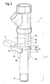
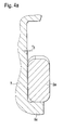
- FIGs 1, 2, 4 and 4a show the fuel injector in the assembled state
- the figures 3a and 3b show it in the unmounted state.
- Figure 1 shows a device known from the prior art for fastening a Fuel injector 1.
- Part 1a of the fuel injector with the connector for the High-pressure manifold (common rail) lies outside the camshaft chamber of the internal combustion engine.
- the part of the fuel injector on the injector side is located itself in the camshaft space and is secured there by means of a traverse 9, which is secured with two fastening screws 3 is attached to the cylinder head.
- a traverse 9 which is secured with two fastening screws 3 is attached to the cylinder head.
- To remove the fuel injector too valve cover 4 must also be removed.
- Figure 2 shows an inventive device for fastening a fuel injector 1 in the cylinder head of the camshaft chamber of an internal combustion engine, containing a fuel injector 1, the shaft 7 tapers towards the injection nozzle 6 from a diameter d 0 to a diameter d 1 and at the tapered shaft of each other opposite lugs 5a and 5b are at a distance d 5 from the injector part 1a with the diameter d 0 .
- the forks 2a and 2b of the fork-shaped clamping claw 2 which have a material thickness d 4 , rest on the shoulders.
- the approaches 5a and 5b are rectangular here on the side facing away from the fuel injector. It can clearly be seen that the point with the shoulders 5a and 5b is not wider than the original diameter d 0 of the fuel injector.
- the distance d 5 must be at least as large as the material thickness d 4 of the forks 2a and 2b.
- FIG 3a the fastening device according to the invention shown in Figure 2 can be seen in supervision and in the unassembled state.
- the clamping claw 2 is shown completely in this figure, as is its fastening screw 3.
- the fuel injector 1 has a diameter d 1 at the point provided with projections 5a and 5b, which is at most as large as the distance d 2 of the two forks 2a and 2b of the claws from each other.
- the point with the shoulders 5a and 5b has a width l 1 which is at most as large as the original diameter d 0 of the fuel injector.
- the width l 1 is preferably less than or equal to the length of the forks l 2 .
- 3b shows a further fastening device according to the invention for securing a fuel injector 1 with a clamping claw 2, which has two forks 2a and 2b and is fastened to the cylinder head via a fastening screw 3.
- the illustration shows the fastening device in the top view and the fuel injector in the unmounted state.
- the approaches 5a and 5b are adapted to the dimensions of the clamping claw at its lowest point 8.
- the shaft of the fuel injector has a diameter d 1 at the point with the shoulders.
- FIG. 4 shows a fuel injector 1 which is fastened by a fastening device according to the invention is secured.
- the fuel injector 1 lies over a cylindrical sealing surface 10 on the undivided valve cover 4.
- the internal combustion engine is designated 11 here.
- Part 1a of the fuel injector with the connector for the high-pressure manifold (Common Rail) is outside the camshaft space.
- the lower part of the In the assembled state shown the fuel injector is inserted into the receiving bore 13 of the cylinder head 12 pressed.
- the fastening screw for the clamping claw is in the cylinder head 12 attached (not shown).
- FIG. 4a shows a section of a fastening device according to the invention in the assembled state.
- a fork 2a of the clamping claw lies on one of the lugs 5a attached to the shaft 7 of the fuel injector.
- the fork 2a of the clamping claw is rounded and has a small distance r 3 from the shaft of the fuel injector. r 3 is in the range of tenths of a mm.
Landscapes
- Engineering & Computer Science (AREA)
- Chemical & Material Sciences (AREA)
- Combustion & Propulsion (AREA)
- Mechanical Engineering (AREA)
- General Engineering & Computer Science (AREA)
- Fuel-Injection Apparatus (AREA)
Applications Claiming Priority (2)
| Application Number | Priority Date | Filing Date | Title |
|---|---|---|---|
| DE10155609 | 2001-11-13 | ||
| DE10155609A DE10155609A1 (de) | 2001-11-13 | 2001-11-13 | Kraftstoffinjektor mit vereinfachter Montage durch ungeteilten Ventildeckel |
Publications (1)
| Publication Number | Publication Date |
|---|---|
| EP1310669A2 true EP1310669A2 (fr) | 2003-05-14 |
Family
ID=7705528
Family Applications (1)
| Application Number | Title | Priority Date | Filing Date |
|---|---|---|---|
| EP02025179A Withdrawn EP1310669A2 (fr) | 2001-11-13 | 2002-11-11 | Injecteur à combustible à montage simple à travers un couvercle de soupape monobloc |
Country Status (4)
| Country | Link |
|---|---|
| US (1) | US20030145833A1 (fr) |
| EP (1) | EP1310669A2 (fr) |
| JP (1) | JP2003148297A (fr) |
| DE (1) | DE10155609A1 (fr) |
Cited By (1)
| Publication number | Priority date | Publication date | Assignee | Title |
|---|---|---|---|---|
| CN103328809A (zh) * | 2011-01-21 | 2013-09-25 | 罗伯特·博世有限公司 | 具有改进的高压接口的燃料喷射阀 |
Families Citing this family (7)
| Publication number | Priority date | Publication date | Assignee | Title |
|---|---|---|---|---|
| JP6755228B2 (ja) * | 2017-10-26 | 2020-09-16 | ヤンマーパワーテクノロジー株式会社 | エンジン |
| US11608804B1 (en) | 2021-08-25 | 2023-03-21 | Caterpillar Inc. | Fuel injector having side-fitted fuel connector for tight packaging in top-feed fuel system |
| US11603817B1 (en) | 2021-08-25 | 2023-03-14 | Caterpillar Inc. | Slim-profile fuel injector for tight packaging in top feed fuel system |
| US11644000B2 (en) * | 2021-08-25 | 2023-05-09 | Caterpillar Inc. | Fuel injector clamp assembly for offset clamping bolt and cylinder head assembly with same |
| US11898516B2 (en) | 2021-08-25 | 2024-02-13 | Caterpillar Inc. | Cylinder head having bore locations arranged for tight packaging of gas exchange and fuel system components |
| US20230064203A1 (en) * | 2021-08-25 | 2023-03-02 | Caterpillar Inc. | Fuel injector having controlled nozzle tip protrusion in cylinder head and cylinder head assembly with same |
| JP2023044793A (ja) * | 2021-09-21 | 2023-04-03 | いすゞ自動車株式会社 | インジェクタの固定構造及びインジェクタの引き抜き方法 |
Citations (3)
| Publication number | Priority date | Publication date | Assignee | Title |
|---|---|---|---|---|
| GB2213197A (en) | 1987-12-05 | 1989-08-09 | Perkins Engines Group | I.C. engine fuel injector clamp |
| DE4413415C1 (de) | 1994-04-18 | 1995-06-08 | Daimler Benz Ag | Vorrichtung zur Befestigung eines Kraftstoffeinspritzventiles |
| EP0957263A1 (fr) | 1998-05-09 | 1999-11-17 | Perkins Engines Company Limited | Bride de fixation d'un injecteur |
-
2001
- 2001-11-13 DE DE10155609A patent/DE10155609A1/de not_active Ceased
-
2002
- 2002-11-11 EP EP02025179A patent/EP1310669A2/fr not_active Withdrawn
- 2002-11-13 JP JP2002329513A patent/JP2003148297A/ja active Pending
- 2002-11-13 US US10/292,877 patent/US20030145833A1/en not_active Abandoned
Patent Citations (3)
| Publication number | Priority date | Publication date | Assignee | Title |
|---|---|---|---|---|
| GB2213197A (en) | 1987-12-05 | 1989-08-09 | Perkins Engines Group | I.C. engine fuel injector clamp |
| DE4413415C1 (de) | 1994-04-18 | 1995-06-08 | Daimler Benz Ag | Vorrichtung zur Befestigung eines Kraftstoffeinspritzventiles |
| EP0957263A1 (fr) | 1998-05-09 | 1999-11-17 | Perkins Engines Company Limited | Bride de fixation d'un injecteur |
Cited By (3)
| Publication number | Priority date | Publication date | Assignee | Title |
|---|---|---|---|---|
| CN103328809A (zh) * | 2011-01-21 | 2013-09-25 | 罗伯特·博世有限公司 | 具有改进的高压接口的燃料喷射阀 |
| CN103328809B (zh) * | 2011-01-21 | 2018-05-15 | 罗伯特·博世有限公司 | 具有改进的高压接口的燃料喷射阀 |
| US10954906B2 (en) | 2011-01-21 | 2021-03-23 | Robert Bosch Gmbh | Fuel injector having an improved high-pressure connection |
Also Published As
| Publication number | Publication date |
|---|---|
| US20030145833A1 (en) | 2003-08-07 |
| JP2003148297A (ja) | 2003-05-21 |
| DE10155609A1 (de) | 2003-05-28 |
Similar Documents
| Publication | Publication Date | Title |
|---|---|---|
| EP2961977B1 (fr) | Dispositif pour l'injection de carburant dans une chambre de combustion d'un moteur à combustion | |
| EP2188516B1 (fr) | Dispositif d'injection de carburant | |
| DE2208646C2 (de) | Vorrichtung zur Befestigung elektromagnetischer Einspritzventile an gemischverdichtenden Brennkraftmaschinen | |
| DE3323010C2 (fr) | ||
| DE202004009755U1 (de) | Vorrichtung zum Ausziehen eines Düsenstockes | |
| DE60024938T2 (de) | Verbindungsanordnung | |
| EP1129286B1 (fr) | Soupape d'injection de carburant pour moteurs a combustion interne | |
| DE69107405T2 (de) | Hochdruck-Dichtungssystem für das Steuerventil eines elektromagnetischen Brennstoffeinspritzventils für Verbrennungsmotoren. | |
| EP2905461B1 (fr) | Installation d'injection de carburant dotée d'un composant destiné à guider le carburant, d'une soupape d'injection de carburant et d'un support | |
| EP1310669A2 (fr) | Injecteur à combustible à montage simple à travers un couvercle de soupape monobloc | |
| DE19528047A1 (de) | Brennkraftmaschine mit einem daran befestigten Saugmodul bzw. Saugrohr und Verfahren zur Befestigung eines Saugmoduls bzw. Saugrohrs an einer Brennkraftmaschine | |
| DE4430339A1 (de) | Anordnung zur Flanschverbindung | |
| DE60217064T2 (de) | Kraftstoff-einspritzdüse | |
| DE3010328A1 (de) | Kraftstoffeinspritzduese fuer brennkraftmaschinen | |
| DE10139622B4 (de) | Einspritzventil | |
| DE19913680B4 (de) | Kraftstoffinjektoreinheit | |
| DE10043084A1 (de) | Spannelement für ein Brennstoffeinspritzventil und Brennstoffeinspritzanlage | |
| DE102019207390B4 (de) | Zylinderkopf für eine Brennkraftmaschine mit Kraftstoffrail und einem Einspritzventil, Verfahren zum Montieren sowie Verwendung hierfür | |
| DE202004009756U1 (de) | Vorrichtung mit Stützgabel zum Ausziehen eines Düsenstockes | |
| DE102005052419B4 (de) | Schraubverbindung | |
| EP2053235B1 (fr) | Moteur à combustion interne doté d'injecteurs de carburant | |
| DE3329418C2 (de) | Abdichtung einer Zylinderkopfhaube am Zylinderkopf einer Brennkraftmaschine | |
| DE102008001533A1 (de) | Einspritzdüsenhalter-Montageverbund mit Spannpratze | |
| WO2008058799A1 (fr) | Injecteur de carburant | |
| EP0068337B1 (fr) | Culbuteur pour commander les soupapes de moteurs à combustion interne |
Legal Events
| Date | Code | Title | Description |
|---|---|---|---|
| PUAI | Public reference made under article 153(3) epc to a published international application that has entered the european phase |
Free format text: ORIGINAL CODE: 0009012 |
|
| AK | Designated contracting states |
Designated state(s): AT BE BG CH CY CZ DE DK EE ES FI FR GB GR IE IT LI LU MC NL PT SE SK TR |
|
| AX | Request for extension of the european patent |
Extension state: AL LT LV MK RO SI |
|
| STAA | Information on the status of an ep patent application or granted ep patent |
Free format text: STATUS: THE APPLICATION IS DEEMED TO BE WITHDRAWN |
|
| 18D | Application deemed to be withdrawn |
Effective date: 20060531 |