EP1310758A2 - Connection entre un tube non refroidi et un tube refroidi, en particulier pour échangeur de chaleur à tubes concentriques - Google Patents
Connection entre un tube non refroidi et un tube refroidi, en particulier pour échangeur de chaleur à tubes concentriques Download PDFInfo
- Publication number
- EP1310758A2 EP1310758A2 EP02025173A EP02025173A EP1310758A2 EP 1310758 A2 EP1310758 A2 EP 1310758A2 EP 02025173 A EP02025173 A EP 02025173A EP 02025173 A EP02025173 A EP 02025173A EP 1310758 A2 EP1310758 A2 EP 1310758A2
- Authority
- EP
- European Patent Office
- Prior art keywords
- connection
- fork
- pipe
- double
- air space
- Prior art date
- Legal status (The legal status is an assumption and is not a legal conclusion. Google has not performed a legal analysis and makes no representation as to the accuracy of the status listed.)
- Withdrawn
Links
Images
Classifications
-
- F—MECHANICAL ENGINEERING; LIGHTING; HEATING; WEAPONS; BLASTING
- F28—HEAT EXCHANGE IN GENERAL
- F28F—DETAILS OF HEAT-EXCHANGE AND HEAT-TRANSFER APPARATUS, OF GENERAL APPLICATION
- F28F9/00—Casings; Header boxes; Auxiliary supports for elements; Auxiliary members within casings
- F28F9/02—Header boxes; End plates
- F28F9/0229—Double end plates; Single end plates with hollow spaces
-
- F—MECHANICAL ENGINEERING; LIGHTING; HEATING; WEAPONS; BLASTING
- F28—HEAT EXCHANGE IN GENERAL
- F28D—HEAT-EXCHANGE APPARATUS, NOT PROVIDED FOR IN ANOTHER SUBCLASS, IN WHICH THE HEAT-EXCHANGE MEDIA DO NOT COME INTO DIRECT CONTACT
- F28D7/00—Heat-exchange apparatus having stationary tubular conduit assemblies for both heat-exchange media, the media being in contact with different sides of a conduit wall
- F28D7/10—Heat-exchange apparatus having stationary tubular conduit assemblies for both heat-exchange media, the media being in contact with different sides of a conduit wall the conduits being arranged one within the other, e.g. concentrically
- F28D7/106—Heat-exchange apparatus having stationary tubular conduit assemblies for both heat-exchange media, the media being in contact with different sides of a conduit wall the conduits being arranged one within the other, e.g. concentrically consisting of two coaxial conduits or modules of two coaxial conduits
-
- F—MECHANICAL ENGINEERING; LIGHTING; HEATING; WEAPONS; BLASTING
- F28—HEAT EXCHANGE IN GENERAL
- F28F—DETAILS OF HEAT-EXCHANGE AND HEAT-TRANSFER APPARATUS, OF GENERAL APPLICATION
- F28F9/00—Casings; Header boxes; Auxiliary supports for elements; Auxiliary members within casings
- F28F9/02—Header boxes; End plates
- F28F9/0246—Arrangements for connecting header boxes with flow lines
-
- F—MECHANICAL ENGINEERING; LIGHTING; HEATING; WEAPONS; BLASTING
- F28—HEAT EXCHANGE IN GENERAL
- F28F—DETAILS OF HEAT-EXCHANGE AND HEAT-TRANSFER APPARATUS, OF GENERAL APPLICATION
- F28F9/00—Casings; Header boxes; Auxiliary supports for elements; Auxiliary members within casings
- F28F9/02—Header boxes; End plates
- F28F9/0246—Arrangements for connecting header boxes with flow lines
- F28F9/0256—Arrangements for coupling connectors with flow lines
Definitions
- the present invention relates to the connection between an uncooled pipe and a cooled pipe.
- this type of connection is addressed to the realization of double-pipe heat exchangers to realize the so-called transfer line exchanger (TLE).
- TLE transfer line exchanger
- the cooled pipe is basically realized with two coaxial pipes inserted one in the other to define an internal pipe run through by the hot fluid (for example the gas coming out of a furnace) and from an external jacket identifying the air space in which runs the cooling fluid (for example water) which is fed into the air space through a union on the side wall of the jacket near the end of the cooled pipe,
- This double-walled structure must be connected to the uncooled pipe which is single-walled.
- a union member with a first tubular single-wall end on which is welded the uncooled pipe and a double-walled opposite end with the two concentric walls on which are welded respectively the internal tube and external jacket of the cooled pipe.
- the cross section of the union member can be assimilated with a fork.
- the walls of the pipes and of the fork union at the contiguous points display different temperatures which produce expansion harmful for the strength of the coupling.
- the welds between the cooled tube and the fork union are in a zone not well cooled since the union for inlet of the cooling fluid into the air space is located further along the cooled pipe.
- the general purpose of the present invention is to remedy the above mentioned shortcomings by making available a stout and relatively economical connection between an uncooled pipe and a cooled pipe and in particular for realizing TLE exchangers.
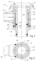
- FIG 1 shows the longitudinal cross section of a connection designated as a whole by reference number 10 and realized in accordance with the present invention.
- Said connection is made between an uncooled pipe (11) and a cooled double-walled pipe (12).
- the cooled pipe 12 has an airspace 13 between the walls run through by cooling fluid let into the air space through a side passage 14 near the connection.
- connection zone 15 has a longitudinal cross section generally shaped like a fork to have a single tubular end 16 connected to the uncooled pipe and an opposite double tubular end 17, 18 to which are connected the corresponding walls 19, 20 of the cooled pipe with double wall. In this manner the bottom 21 of the fork constitutes a terminal closing of the air space 13.
- baffle member 22 which divers toward the bottom 21 of the fork the cooling fluid which enters the air space through the side passage 14 before the cooling fluid proceeds along the double-walled pipe.
- the forked connection zone 15 is advantageously made with a separate forked member 23 to the end 16 of which is welded the uncooled pipe and at the opposite double end 17, 18 is welded the double-walled pipe.
- the baffle member is formed of a cylindrical baffle plate arranged in an intermediate position between the double walls and with extension along the same double walls.
- a first end 24 of the cylindrical baffle plate opposite the bottom 21 of the fork is closed on the outermost wall of the air space while the opposite end 30 of the cylindrical baffle plate terminates near the bottom 21 of the fork to allow a space for passage of the fluid between the opposing faces of the baffle plate.
- the baffle plate is advantageously bent outward to meet with the outermost wall of the air space so as to close the passage.
- spacers 25 arranged radially in the air space as seen also in FIG 2.
- the forked member has the two ends 17, 18 welded to the two walls of the double-walled pipe with weld zones 26, 27 of the two walls facing opposite faces of the baffle member 22.
- weld zone 26 of the outermost wall is nearer the bottom 21 of the fork with respect to the weld zone 27 of the innermost wall.
- the bottom 21 of the fork is in rounded radial section with curvature axis generally near the free end of the baffle 22 to have a virtually constant section for passage of the fluid between the two faces of the baffle plate.
- the cooling fluid is obliged to run along the path shown by the arrows in FIG 1. In this manner the connection zone is cooled effectively by the process fluid and no refractory layer in the bottom of the fork or other systems are necessary to hold temperatures low.
- the bottom can be shallow advantageously for cooling and economy of materials.
- connection realized in this manner while not having all the complications of prior art connections is exceptionally strong and has long life while not displaying those points of maximum stress which were found in connections realized in accordance with the prior art and which were responsible for the inevitable periodic breakages.
Landscapes
- Engineering & Computer Science (AREA)
- Physics & Mathematics (AREA)
- Thermal Sciences (AREA)
- Mechanical Engineering (AREA)
- General Engineering & Computer Science (AREA)
- Heat-Exchange Devices With Radiators And Conduit Assemblies (AREA)
- Rigid Pipes And Flexible Pipes (AREA)
Applications Claiming Priority (2)
| Application Number | Priority Date | Filing Date | Title |
|---|---|---|---|
| IT2001MI000594U ITMI20010594U1 (it) | 2001-11-12 | 2001-11-12 | Giunzione di un tubo non raffreddato e di un tubo raffreddato, in particolare per scambiatori di calore a doppio tubo |
| ITMI20010594 | 2001-11-12 |
Publications (2)
| Publication Number | Publication Date |
|---|---|
| EP1310758A2 true EP1310758A2 (fr) | 2003-05-14 |
| EP1310758A3 EP1310758A3 (fr) | 2004-08-11 |
Family
ID=11447326
Family Applications (1)
| Application Number | Title | Priority Date | Filing Date |
|---|---|---|---|
| EP02025173A Withdrawn EP1310758A3 (fr) | 2001-11-12 | 2002-11-11 | Connection entre un tube non refroidi et un tube refroidi, en particulier pour échangeur de chaleur à tubes concentriques |
Country Status (2)
| Country | Link |
|---|---|
| EP (1) | EP1310758A3 (fr) |
| IT (1) | ITMI20010594U1 (fr) |
Cited By (2)
| Publication number | Priority date | Publication date | Assignee | Title |
|---|---|---|---|---|
| EP1722181A3 (fr) * | 2005-05-11 | 2011-11-23 | OLMI S.p.A. | Connexion entre tube refroidi et tube non refroidi dans un échangeur de chaleur à double tubes |
| IT201800020257A1 (it) * | 2018-12-20 | 2020-06-20 | Hexsol Italy Srl | Giunzioni per tubi a doppia parete in scambiatori di calore e scambiatori di calore e scambiatori con tali giunzioni |
Family Cites Families (5)
| Publication number | Priority date | Publication date | Assignee | Title |
|---|---|---|---|---|
| US2410912A (en) * | 1944-05-02 | 1946-11-12 | Keystone Mfg Co | Heat exchanger |
| FR1590170A (fr) * | 1968-09-27 | 1970-04-13 | ||
| NL6919308A (fr) * | 1968-12-27 | 1970-06-30 | ||
| GB1418732A (en) * | 1973-01-30 | 1975-12-24 | Clarke Chapman Ltd | Heat exchangers |
| US5813453A (en) * | 1996-06-01 | 1998-09-29 | Deutsche Babcock-Borsig Ag | Heat exchanger for cooling cracked gas |
-
2001
- 2001-11-12 IT IT2001MI000594U patent/ITMI20010594U1/it unknown
-
2002
- 2002-11-11 EP EP02025173A patent/EP1310758A3/fr not_active Withdrawn
Cited By (5)
| Publication number | Priority date | Publication date | Assignee | Title |
|---|---|---|---|---|
| EP1722181A3 (fr) * | 2005-05-11 | 2011-11-23 | OLMI S.p.A. | Connexion entre tube refroidi et tube non refroidi dans un échangeur de chaleur à double tubes |
| IT201800020257A1 (it) * | 2018-12-20 | 2020-06-20 | Hexsol Italy Srl | Giunzioni per tubi a doppia parete in scambiatori di calore e scambiatori di calore e scambiatori con tali giunzioni |
| WO2020128957A1 (fr) * | 2018-12-20 | 2020-06-25 | Hexsol Italy Srl | Jonctions pour tubes à double paroi dans des échangeurs de chaleur et échangeurs comprenant de telles jonctions |
| EP3899396B1 (fr) | 2018-12-20 | 2022-09-14 | Hexsol Italy Srl | Echangeur de chaleur comportant une jonction d'extremite |
| US11656031B2 (en) | 2018-12-20 | 2023-05-23 | Hexsol Italy Srl | Junctions for double-walled tubes in heat exchangers and exchangers with such junctions |
Also Published As
| Publication number | Publication date |
|---|---|
| ITMI20010594U1 (it) | 2003-05-12 |
| EP1310758A3 (fr) | 2004-08-11 |
Similar Documents
| Publication | Publication Date | Title |
|---|---|---|
| US6446714B1 (en) | Brazed condenser for an air conditioner | |
| IT9019797A1 (it) | Giunzione di un tubo non raffreddato con un tubo raffreddato | |
| US20070235175A1 (en) | Header plate for use in a heat exchanger | |
| US7287578B2 (en) | Connection between a cooled double-wall pipe and an uncooled pipe and double-pipe heat exchanger including said connection | |
| US7681922B2 (en) | Connection between cooled pipe and uncooled pipe in a double-pipe heat exchanger | |
| EP1310758A2 (fr) | Connection entre un tube non refroidi et un tube refroidi, en particulier pour échangeur de chaleur à tubes concentriques | |
| BRPI1002138A2 (pt) | trocador de calor para refrigeração de gás de reação, incluindo uma conexão tubular entre um tubo refrigerado e um tubo não refrigerado | |
| CN207649426U (zh) | 一种换热器 | |
| CN109210971A (zh) | 翅片式热传递装置 | |
| IE50686B1 (en) | Space heater | |
| CN112005071A (zh) | 双管热交换器及其制造方法 | |
| CN102095331A (zh) | 用于共轴管-热交换器的连接装置 | |
| EP1519134A2 (fr) | Echangeur de chaleur | |
| US20050155748A1 (en) | Concentric tube heat exchanger end seal therefor | |
| US6129146A (en) | Manifold for a brazed radiator | |
| CN108387000A (zh) | 不锈钢换热器、燃气热水装置及换热器的制作方法 | |
| US5626187A (en) | Heat-exchanger tube | |
| US5992157A (en) | Temperature controlled tank | |
| EP0231962A1 (fr) | Réchauffeur avec préparateur d'eau chaude sanitaire et échangeur de chaleur pour un tel réchauffeur | |
| US3861461A (en) | Bayonet tube heat exchange | |
| JP2000121267A (ja) | 接続片を備えた熱交換器 | |
| US20050045315A1 (en) | Concentric tube heat exchanger and end seal therefor | |
| JPH09133491A (ja) | 熱交換器の製造方法 | |
| CN207064189U (zh) | 吸气隔热管和压缩机 | |
| CN217737164U (zh) | 一种贯流式蒸汽锅炉罐体 |
Legal Events
| Date | Code | Title | Description |
|---|---|---|---|
| PUAI | Public reference made under article 153(3) epc to a published international application that has entered the european phase |
Free format text: ORIGINAL CODE: 0009012 |
|
| AK | Designated contracting states |
Designated state(s): AT BE BG CH CY CZ DE DK EE ES FI FR GB GR IE IT LI LU MC NL PT SE SK TR |
|
| AX | Request for extension of the european patent |
Extension state: AL LT LV MK RO SI |
|
| PUAL | Search report despatched |
Free format text: ORIGINAL CODE: 0009013 |
|
| AK | Designated contracting states |
Kind code of ref document: A3 Designated state(s): AT BE BG CH CY CZ DE DK EE ES FI FR GB GR IE IT LI LU MC NL PT SE SK TR |
|
| AX | Request for extension of the european patent |
Extension state: AL LT LV MK RO SI |
|
| 17P | Request for examination filed |
Effective date: 20050209 |
|
| AKX | Designation fees paid |
Designated state(s): AT BE BG CH CY CZ DE DK EE ES FI FR GB GR IE IT LI LU MC NL PT SE SK TR |
|
| 17Q | First examination report despatched |
Effective date: 20050524 |
|
| STAA | Information on the status of an ep patent application or granted ep patent |
Free format text: STATUS: THE APPLICATION HAS BEEN WITHDRAWN |
|
| 18W | Application withdrawn |
Effective date: 20050906 |