EP1311034B1 - Elektrisches Installationsgerät mit Schiebedeckel - Google Patents
Elektrisches Installationsgerät mit Schiebedeckel Download PDFInfo
- Publication number
- EP1311034B1 EP1311034B1 EP02023848A EP02023848A EP1311034B1 EP 1311034 B1 EP1311034 B1 EP 1311034B1 EP 02023848 A EP02023848 A EP 02023848A EP 02023848 A EP02023848 A EP 02023848A EP 1311034 B1 EP1311034 B1 EP 1311034B1
- Authority
- EP
- European Patent Office
- Prior art keywords
- sliding cover
- installation device
- locking
- sliding
- ball
- Prior art date
- Legal status (The legal status is an assumption and is not a legal conclusion. Google has not performed a legal analysis and makes no representation as to the accuracy of the status listed.)
- Expired - Lifetime
Links
- 238000009434 installation Methods 0.000 claims description 9
- 230000002040 relaxant effect Effects 0.000 claims description 3
- 239000012530 fluid Substances 0.000 claims 2
- 238000009429 electrical wiring Methods 0.000 abstract 1
- 238000010616 electrical installation Methods 0.000 description 9
- 239000007788 liquid Substances 0.000 description 4
- 238000007789 sealing Methods 0.000 description 3
- 230000007774 longterm Effects 0.000 description 2
- 230000001681 protective effect Effects 0.000 description 2
- XLYOFNOQVPJJNP-UHFFFAOYSA-N water Substances O XLYOFNOQVPJJNP-UHFFFAOYSA-N 0.000 description 2
- 238000013016 damping Methods 0.000 description 1
- 238000003780 insertion Methods 0.000 description 1
- 230000037431 insertion Effects 0.000 description 1
- 239000000463 material Substances 0.000 description 1
- 230000000149 penetrating effect Effects 0.000 description 1
- 229920001296 polysiloxane Polymers 0.000 description 1
Images


Classifications
-
- H—ELECTRICITY
- H01—ELECTRIC ELEMENTS
- H01R—ELECTRICALLY-CONDUCTIVE CONNECTIONS; STRUCTURAL ASSOCIATIONS OF A PLURALITY OF MUTUALLY-INSULATED ELECTRICAL CONNECTING ELEMENTS; COUPLING DEVICES; CURRENT COLLECTORS
- H01R13/00—Details of coupling devices of the kinds covered by groups H01R12/70 or H01R24/00 - H01R33/00
- H01R13/46—Bases; Cases
- H01R13/52—Dustproof, splashproof, drip-proof, waterproof, or flameproof cases
- H01R13/5213—Covers
-
- H—ELECTRICITY
- H01—ELECTRIC ELEMENTS
- H01R—ELECTRICALLY-CONDUCTIVE CONNECTIONS; STRUCTURAL ASSOCIATIONS OF A PLURALITY OF MUTUALLY-INSULATED ELECTRICAL CONNECTING ELEMENTS; COUPLING DEVICES; CURRENT COLLECTORS
- H01R13/00—Details of coupling devices of the kinds covered by groups H01R12/70 or H01R24/00 - H01R33/00
- H01R13/44—Means for preventing access to live contacts
- H01R13/447—Shutter or cover plate
-
- H—ELECTRICITY
- H01—ELECTRIC ELEMENTS
- H01R—ELECTRICALLY-CONDUCTIVE CONNECTIONS; STRUCTURAL ASSOCIATIONS OF A PLURALITY OF MUTUALLY-INSULATED ELECTRICAL CONNECTING ELEMENTS; COUPLING DEVICES; CURRENT COLLECTORS
- H01R24/00—Two-part coupling devices, or either of their cooperating parts, characterised by their overall structure
- H01R24/76—Two-part coupling devices, or either of their cooperating parts, characterised by their overall structure with sockets, clips or analogous contacts and secured to apparatus or structure, e.g. to a wall
- H01R24/78—Two-part coupling devices, or either of their cooperating parts, characterised by their overall structure with sockets, clips or analogous contacts and secured to apparatus or structure, e.g. to a wall with additional earth or shield contacts
Definitions
- the invention relates to an electrical installation device with sliding cover according to the preamble of claim 1.
- the invention may, for example, in Sockets of any embodiment (in particular flush-mounted or surface-mounted protective contact sockets), Antenna sockets, speaker sockets, telecommunication device sockets etc. are used.
- this hinged lid usually has a spring-loaded closure system, which opens the Hinged lid manually against a spring force and a self-closing with Help this spring force allows. It is disadvantageous that the hinged lid due This spring force closes with great vehemence, which on the one hand are too uncomfortable Noise leads and on the other hand in long-term operation damage to the installation device (For example, crack of the hinged lid or breakage of storage) result may have.
- the invention is based on the object, an electrical installation device with sliding cover specify the type mentioned, which is an opening and closing the sliding cover without unpleasant noise allows.
- the advantages achieved by the invention are in particular that the proposed Sliding lid drive system a manual closing and after short operation of the sliding cover allows automatic opening of the sliding cover, wherein it is ensured by an automatic locking that the sliding cover remains in the respective desired closed position. During the Opening and closing the sliding lid will not cause any loud noises. At the Opening / closing the sliding cover will not cause any damage during long-term operation on.
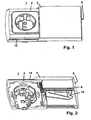
- Fig. 1 is a perspective view of the front side of an electrical installation device shown. It is the main body 2 of the electrical installation device 1 - in the exemplary embodiment is a flush-mounted protective contact socket - to recognize, with this body 2 (with socket) by means of a Schiebedekkels 3 is coverable.
- a guide system 15 allows the movement of the sliding cover 3 along the body 2 within predetermined limits. Opening the Sliding lid 3 is by a short pressure on an actuating surface 4 at the Front side of the sliding cover 3 introduced. The opening of the sliding cover 3 takes place then automatically with the help of a sliding lid drive system. The closing the sliding cover 3 is effected by continuous pressure on the actuating surface. 4 up to a stop. 1 shows the position with the sliding cover 3 open.
- FIG. 2 is a perspective view of the back of an electrical installation device shown. It is turn the main body 2 of the electrical installation device 1 shown with sliding cover 3 in the open position. This open position gives a look at the inside of the sliding cover 3 free and it is one in Schiebedekkel 3 molded rack 8 of the sliding lid drive system and an im Sliding lid 3 molded locking contour 16 of the sliding lid locking system to recognize.
- FIG. 3 is a sectional view with closed sliding cover (and thus covered and protected against splashing water and introduction of objects Socket).
- This sectional view shows the individual components of the Sliding lid drive unit, namely a gear 5 with axis 6, wherein a coil spring 7 encloses the axis 6.
- the axis 6 has at its one end a bearing pin 9 for a first storage of the main body 2 and at its other end - near the gear 5 - one formed for example as a cone or cylinder Rotary body 12 for a second storage of the base body 2.
- the base body 2 has one with a (preferably viscous) liquid silicone-filled pocket 11 into which the rotary body 12 dips, wherein the centering of the rotary body 12 and the seal of the pocket 11th with the aid of a sealing ring 14, which in a between rotary body 12 and Gear 5 trained groove is inserted.
- a (preferably viscous) liquid silicone-filled pocket 11 into which the rotary body 12 dips, wherein the centering of the rotary body 12 and the seal of the pocket 11th with the aid of a sealing ring 14, which in a between rotary body 12 and Gear 5 trained groove is inserted.
- Fig. 3 further shows as a component of the sliding lid locking system one between sliding cover 3 and base 2 by means of the locking contour 16th and a pan (see numeral 2 in Fig. 9) guided ball 17th
- This guide system 15 of the sliding cover 3 is shown in Fig. 3.
- This guide system 15 is formed of a plurality of guide webs, which in corresponding Guide grooves slide, with both guide webs and guide grooves both in the outer casing of the base body 2, as well as in the inner shell of the Sliding lid 3 are formed.
- Fig. 4 is a section of the back of base 2 and sliding cover 3 with Components of the proposed sliding lid drive system shown. in the individual are the engaging in the rack 8 gear 5 and the axis 6 to see wound coil spring 7.
- the bearing pin 9 of the axis 6 engages in the first Storage of the body 2 a (see receiving opening 10 on the main body in Fig. 5) and is therefore not recognizable.
- the same engages the rotary body 12 in the bag 11 on the base body 2 and is therefore also not recognizable.
- Essential for the function of the drive system 5 + 6 + 7 is the intervention of the one End of the coil spring 7 in a recess of the gear 5 and the engagement of the other end of the coil spring 7 in a recess of the body at the place of first storage.
- FIG. 5 is a section of the front of a body when removed Sliding lid and remote sliding lid drive system shown.
- This section shows in particular the pocket 11 on the base body 2, in which the rotary body 12 of the drive unit 5 + 6 + 7 is introduced, wherein the sealing ring 14 (O-ring) ensures the sealing and centering.
- Fig. 6 is formed of a gear 5, axis 6 and coil spring 7 drive unit the sliding lid drive system shown, wherein the bearing pin 9 at the end of Axis 6 is clearly visible.
- the Rotary body 12 with a plurality of notches 13 in its outer circumferential surface. These scores 13 are in storage of the rotating body 12 in the pocket 11 with the in the pocket 11th filled liquid.
- the building component 5 + 6 + 9 + 12 is preferred formed in one piece (made of plastic material).
- FIG. 7 is a sectional view with the sliding cover open (and thus more accessible Socket).
- the opening direction of the sliding cover 3 is indicated by arrow E.
- the ball 17 is in a in the top of the Base body 2 molded trough 22 movably mounted or guided.
- the sliding cover 3 relative to the base body 2 are through the in the inside the sliding cover 3 molded locking contour 16 for the guided therein Ball 17 inter alia a locking position 18 when fully closed Sliding lid 3 and an end position 19 with fully open sliding cover. 3 educated.
- FIG. 7 further shows the guide system 15 of the sliding cover 3.
- the relaxing coil spring 7 sets the gear 5 in Rotation and by the engagement of the gear 5 in the rack 8 is the automatic opening of the sliding cover 3.
- the rotation of the provided with notches 13th Rotary body 12 within the liquid-filled bag 11 is a Throttling the opening speed of the sliding cover 3 to a desired Value, because the rotational movement of the gear 5 with rotary body 12 is a resistance opposite, what a muted, d. H. even and slow Opening (extension) of the sliding cover causes.
- phase IV the gear 5 is set by the rack 8 in rotation and thereby the tensioning of the coil spring 7 takes place.
- the drive system is caused the rotation of the rotating body within the pocket 11 also during closing a subdued movement.
- the rotary body 12 can be realized, which generally a rotation of the rotary body within to resist a liquid.
- Fig. 9 is a section of the front of the base body 2 when removed Sliding lid shown.
- These are the assembled drive system 5 + 6 + 7 with bearing journals 9 as well as molded in the base body 2 trough 22 to recognize, where seen is that the trough 22, a movement of the ball 17 transverse to the opening direction E of the sliding cover 3 within the predetermined by the locking contour 16 Limits allows, but at the same time a movement in the longitudinal direction of the opening direction E stops.
Landscapes
- Casings For Electric Apparatus (AREA)
- Motor Or Generator Frames (AREA)
- Operating, Guiding And Securing Of Roll- Type Closing Members (AREA)
- Power-Operated Mechanisms For Wings (AREA)
- Transmission Devices (AREA)
Description
- Fig.1
- eine perspektivische Ansicht der Frontseite eines elektrischen Installationsgerätes,
- Fig. 2
- eine perspektivische Ansicht der Rückseite eines elektrischen Installationsgerätes,
- Fig. 3
- eine Schnittdarstellung mit geschlossenem Schiebedeckel,
- Fig. 4
- einen Ausschnitt der Rückseite mit Komponenten des Deckel-Antriebssystems,
- Fig. 5
- einen Ausschnitt der Vorderseite eines Grundkörpers bei abgenommenen Schiebedeckel und entferntem Deckel-Antriebssystem,
- Fig. 6
- eine Antriebseinheit des Deckel-Antriebssystems,
- Fig. 7
- eine Schnittdarstellung mit geöffnetem Schiebedeckel,
- Fig. 8
- eine Ansicht der Innenseite eines Schiebedeckels,
- Fig. 9
- einen Ausschnitt der Vorderseite des Grundkörpers bei abgenommenem Schiebedeckel,
Claims (7)
- Elektrisches Installationsgerät mit Schiebedeckel (3), welcher mittels eines Führungssystems (15) relativ zum Grundkörper (2) des elektrischen Installationsgerätes (1) geführt zwischen einer geöffneten und einer geschlossenen Position verschiebbar ist, mit einem Schiebedeckel-Antriebssystemmit einer an der Innenseite des Schiebedeckels (3) angeordneten Zahnstange (8),mit einer am Grundkörper (2) gelagerten Schiebedeckel-Antriebseinheit mit Zahnrad (5), Achse (6) und einer die Achse umschließenden Spiralfeder (7),wobei während einer Relativbewegung zwischen Schiebedeckel (3) und Grundkörper (2) infolge des Eingriffs des Zahnrades (5) in der Zahnstange (8) ein Spannen/Entspannen der Spiralfeder (7) erfolgt,wobei die Schiebedeckel-Antriebseinheit (5+6+7) einen Drehkörper (12) aufweist, dadurch gekennzeichnet dass der Drehkörper in eine mit Flüssigkeit gefüllte Tasche (11) des Grundkörpers (2) greift, wobei der Drehkörper derart ausgebildet ist, dass einer Rotation des Drehkörpers in der Flüssigkeit ein Widerstand entgegengesetzt wird, wodurch eine gedämpfte Rotationsbewegung der Antriebseinheit (5+6+7) erfolgt.
- Installationsgerät nach Anspruch 1, dadurch gekennzeichnet, dass die Zahnstange (8) in der Innenseite des Schiebedeckels (3) eingeformt ist.
- Installationsgerät nach Anspruch 1 und/oder 2, gekennzeichnet durch ein Schiebedeckel-Verriegelungssystem, welches den Schiebedeckel (3) in geschlossener Position in einer definierten Verriegelungsposition (18) verriegelt.
- Installationsgerät nach Anspruch 3, dadurch gekennzeichnet, dass das Schiebedeckel-Verriegelungssystem durch eine an der Innenseite des Schiebedeckels (3) angeordnete Verriegelungskontur (16), eine am Grundkörper (2) angeordnete Wanne (22) und eine Kugel (1) gebildet ist, wobei die Kugel (17) während einer Relativbewegung des Schiebedeckels (3) gegenüber dem Grundkörper (2) in einem Kugelkreislauf zwischen Verriegelungskontur (16) und Wanne (22) geführt wird.
- Installationsgerät nach Anspruch 4, dadurch gekennzeichnet, dass neben der Verriegelungsposition (18) für vollständig geschlossenen Schiebedeckel (3) eine Zwischenposition (20) vorgesehen ist, in welche die Kugel (17) nach kurzem Druck auf eine Betätigungsfläche (4) des Schiebedeckels (3) gleitet, wodurch ein Lösen der Verriegelung erfolgt und das vom Schiebedeckel-Antriebssystem unterstützte selbsttätige Öffnen des Schiebedeckels eingeleitet wird.
- Installationsgerät nach Anspruch 4 und/oder 5, dadurch gekennzeichnet, dass neben der Verriegelungsposition (18) für vollständig geschlossenen Schiebedeckel (3) eine Zwischenposition (21) vorgesehen ist, in welche die Kugel (17) nach kontinuierlichem Druck auf eine Betätigungsfläche (4) des Schiebedeckels (3) bis zu einem Anschlag gleitet, wodurch die Führung der Kugel (17) in die Verriegelungsposition (18) eingeleitet wird.
- Installationsgerät nach einem der Ansprüche 4 bis 6, dadurch gekennzeichnet, dass die Verriegelungskontur (16) in der Innenseite des Schiebedeckels (3) eingeformt ist.
Applications Claiming Priority (2)
| Application Number | Priority Date | Filing Date | Title |
|---|---|---|---|
| DE10155502A DE10155502A1 (de) | 2001-11-13 | 2001-11-13 | Elektrisches Installationsgerät mit Schiebedeckel |
| DE10155502 | 2001-11-13 |
Publications (3)
| Publication Number | Publication Date |
|---|---|
| EP1311034A2 EP1311034A2 (de) | 2003-05-14 |
| EP1311034A3 EP1311034A3 (de) | 2004-07-14 |
| EP1311034B1 true EP1311034B1 (de) | 2005-09-07 |
Family
ID=7705463
Family Applications (1)
| Application Number | Title | Priority Date | Filing Date |
|---|---|---|---|
| EP02023848A Expired - Lifetime EP1311034B1 (de) | 2001-11-13 | 2002-10-24 | Elektrisches Installationsgerät mit Schiebedeckel |
Country Status (4)
| Country | Link |
|---|---|
| EP (1) | EP1311034B1 (de) |
| AT (1) | ATE304230T1 (de) |
| DE (2) | DE10155502A1 (de) |
| NO (1) | NO20025396L (de) |
Families Citing this family (6)
| Publication number | Priority date | Publication date | Assignee | Title |
|---|---|---|---|---|
| JP4640843B2 (ja) * | 2004-08-19 | 2011-03-02 | 富士通株式会社 | コンピュータおよびコンピュータ用筐体 |
| DE102007063585B4 (de) * | 2007-12-29 | 2012-08-09 | Merten Gmbh & Co. Kg | Elektrisches Installationsgerät |
| CH701228A1 (de) * | 2009-06-08 | 2010-12-15 | Feller Ag | Elektrischer Apparat für Hausinstallationen. |
| WO2014116600A1 (en) * | 2013-01-22 | 2014-07-31 | Hypertronics Corporation | Coupling system including a receptacle housing with a rotating domed door |
| GB2515045B (en) * | 2013-06-12 | 2015-09-16 | Munster Simms Eng Ltd | Socket assembly |
| DE102021107848B4 (de) | 2021-03-29 | 2026-01-22 | Bachmann Gmbh | Dosengehäuse; Verfahren zur Bedienung eines Dosengehäuses |
Family Cites Families (9)
| Publication number | Priority date | Publication date | Assignee | Title |
|---|---|---|---|---|
| US4168104A (en) * | 1978-06-29 | 1979-09-18 | Buschow Dean W | Electrical receptacle |
| US4185881A (en) * | 1978-07-19 | 1980-01-29 | Playsafe Electrics Proprietary Limited | Electrical plug and socket arrangement |
| DE3447646C2 (de) * | 1984-12-28 | 1994-12-01 | Albert Stewing | Kabelverzweigerschrank |
| CA1280184C (en) * | 1987-09-16 | 1991-02-12 | Michel Poirier | Safety guard for electrical wall outlet |
| US5198618A (en) * | 1992-02-10 | 1993-03-30 | Gary Shieh | Safety cover plate for an electrical socket |
| JP2916575B2 (ja) * | 1994-07-19 | 1999-07-05 | 矢崎総業株式会社 | コネクタ蓋開閉構造 |
| US5769646A (en) * | 1995-07-25 | 1998-06-23 | Dell U.S.A., L.P. | Integrated electrical connector guard device for use in a personal computer |
| FR2742626B1 (fr) * | 1995-12-19 | 1998-02-20 | Eurocopter France | Dispositif de guidage, d'entrainement et de verrouillage d'un tiroir d'equipement electrique ou electronique dans une armoire |
| DE19646645C2 (de) * | 1996-11-12 | 1999-11-04 | Daimler Chrysler Ag | Behälter |
-
2001
- 2001-11-13 DE DE10155502A patent/DE10155502A1/de not_active Withdrawn
-
2002
- 2002-10-24 DE DE50204162T patent/DE50204162D1/de not_active Expired - Lifetime
- 2002-10-24 AT AT02023848T patent/ATE304230T1/de not_active IP Right Cessation
- 2002-10-24 EP EP02023848A patent/EP1311034B1/de not_active Expired - Lifetime
- 2002-11-11 NO NO20025396A patent/NO20025396L/no not_active Application Discontinuation
Also Published As
| Publication number | Publication date |
|---|---|
| DE50204162D1 (de) | 2005-10-13 |
| NO20025396L (no) | 2003-05-14 |
| DE10155502A1 (de) | 2003-05-22 |
| EP1311034A2 (de) | 2003-05-14 |
| EP1311034A3 (de) | 2004-07-14 |
| ATE304230T1 (de) | 2005-09-15 |
| NO20025396D0 (no) | 2002-11-11 |
Similar Documents
| Publication | Publication Date | Title |
|---|---|---|
| DE4004211C2 (de) | Elektrischer Rauschabsorber | |
| DE69015425T2 (de) | Dämpfer mit viskoser Flüssigkeit für Klapptüre. | |
| DE69111409T2 (de) | Zylinderschlösser, mit auswechselbaren Zylindern. | |
| DE2526890C2 (de) | Elektrische Hohlwanddose | |
| DE102007001591A1 (de) | Tragbare, handgeführte Werkzeugmaschine | |
| EP0228527B1 (de) | Fenster- und Türbeschlag | |
| DE4008982A1 (de) | Im ohr zu tragendes hoergeraet oder otoplastik mit einem belueftungskanal | |
| EP1311034A2 (de) | Elektrisches Installationsgerät mit Schiebedeckel | |
| DE4341087C2 (de) | Abgedichtete Schaltvorrichtung | |
| DE29610582U1 (de) | Rohrschelle | |
| EP1564360B1 (de) | Vorrichtung zum motorischen Öffnen und Schliessen eines Karosserieteils | |
| DE2705627A1 (de) | Kabelfensterheber | |
| CH715484B1 (de) | Scharnier mit einer Kabeldurchführung sowie ein Verfahren zum Montieren bzw. Demontieren des Scharniers. | |
| DE3239041A1 (de) | Moebelscharnier | |
| EP1524401B1 (de) | Klemmhalterung | |
| DE2917006A1 (de) | Verriegelungseinheit fuer tueren oder deckel von gehaeusekoerpern | |
| EP1532913A2 (de) | Einrichtung zum Dämpfen von WC-Sitzen und/oder WC-Deckeln | |
| DE9314325U1 (de) | Flügelscharnier | |
| EP1308593A2 (de) | Kabelkanalübergang zwischen einem Türflügel und einer Türzarge | |
| EP2250954B1 (de) | Duschabtrennvorrichtung | |
| EP0410437B1 (de) | Profilschliesszylinder | |
| DE19855210C2 (de) | Verfahren zum Herstellen eines Stiftes | |
| DE19920829C1 (de) | Scharnier | |
| DE20108224U1 (de) | Möbel, insbesondere Schrank | |
| DE822944C (de) | Zylinderschloss |
Legal Events
| Date | Code | Title | Description |
|---|---|---|---|
| PUAI | Public reference made under article 153(3) epc to a published international application that has entered the european phase |
Free format text: ORIGINAL CODE: 0009012 |
|
| AK | Designated contracting states |
Designated state(s): AT BE BG CH CY CZ DE DK EE ES FI FR GB GR IE IT LI LU MC NL PT SE SK TR |
|
| AX | Request for extension of the european patent |
Extension state: AL LT LV MK RO SI |
|
| PUAL | Search report despatched |
Free format text: ORIGINAL CODE: 0009013 |
|
| AK | Designated contracting states |
Kind code of ref document: A3 Designated state(s): AT BE BG CH CY CZ DE DK EE ES FI FR GB GR IE IT LI LU MC NL PT SE SK TR |
|
| AX | Request for extension of the european patent |
Extension state: AL LT LV MK RO SI |
|
| 17P | Request for examination filed |
Effective date: 20040827 |
|
| 17Q | First examination report despatched |
Effective date: 20041007 |
|
| GRAP | Despatch of communication of intention to grant a patent |
Free format text: ORIGINAL CODE: EPIDOSNIGR1 |
|
| AKX | Designation fees paid |
Designated state(s): AT BE BG CH CY CZ DE DK EE ES FI FR GB GR IE IT LI LU MC NL PT SE SK TR |
|
| GRAS | Grant fee paid |
Free format text: ORIGINAL CODE: EPIDOSNIGR3 |
|
| GRAA | (expected) grant |
Free format text: ORIGINAL CODE: 0009210 |
|
| AK | Designated contracting states |
Kind code of ref document: B1 Designated state(s): AT BE BG CH CY CZ DE DK EE ES FI FR GB GR IE IT LI LU MC NL PT SE SK TR |
|
| PG25 | Lapsed in a contracting state [announced via postgrant information from national office to epo] |
Ref country code: TR Free format text: LAPSE BECAUSE OF FAILURE TO SUBMIT A TRANSLATION OF THE DESCRIPTION OR TO PAY THE FEE WITHIN THE PRESCRIBED TIME-LIMIT Effective date: 20050907 Ref country code: IT Free format text: LAPSE BECAUSE OF FAILURE TO SUBMIT A TRANSLATION OF THE DESCRIPTION OR TO PAY THE FEE WITHIN THE PRESCRIBED TIME-LIMIT;WARNING: LAPSES OF ITALIAN PATENTS WITH EFFECTIVE DATE BEFORE 2007 MAY HAVE OCCURRED AT ANY TIME BEFORE 2007. THE CORRECT EFFECTIVE DATE MAY BE DIFFERENT FROM THE ONE RECORDED. Effective date: 20050907 Ref country code: GB Free format text: LAPSE BECAUSE OF FAILURE TO SUBMIT A TRANSLATION OF THE DESCRIPTION OR TO PAY THE FEE WITHIN THE PRESCRIBED TIME-LIMIT Effective date: 20050907 Ref country code: EE Free format text: LAPSE BECAUSE OF FAILURE TO SUBMIT A TRANSLATION OF THE DESCRIPTION OR TO PAY THE FEE WITHIN THE PRESCRIBED TIME-LIMIT Effective date: 20050907 Ref country code: FI Free format text: LAPSE BECAUSE OF FAILURE TO SUBMIT A TRANSLATION OF THE DESCRIPTION OR TO PAY THE FEE WITHIN THE PRESCRIBED TIME-LIMIT Effective date: 20050907 Ref country code: SK Free format text: LAPSE BECAUSE OF FAILURE TO SUBMIT A TRANSLATION OF THE DESCRIPTION OR TO PAY THE FEE WITHIN THE PRESCRIBED TIME-LIMIT Effective date: 20050907 Ref country code: CZ Free format text: LAPSE BECAUSE OF FAILURE TO SUBMIT A TRANSLATION OF THE DESCRIPTION OR TO PAY THE FEE WITHIN THE PRESCRIBED TIME-LIMIT Effective date: 20050907 Ref country code: NL Free format text: LAPSE BECAUSE OF FAILURE TO SUBMIT A TRANSLATION OF THE DESCRIPTION OR TO PAY THE FEE WITHIN THE PRESCRIBED TIME-LIMIT Effective date: 20050907 Ref country code: IE Free format text: LAPSE BECAUSE OF FAILURE TO SUBMIT A TRANSLATION OF THE DESCRIPTION OR TO PAY THE FEE WITHIN THE PRESCRIBED TIME-LIMIT Effective date: 20050907 |
|
| REG | Reference to a national code |
Ref country code: GB Ref legal event code: FG4D Free format text: NOT ENGLISH |
|
| REG | Reference to a national code |
Ref country code: CH Ref legal event code: EP |
|
| REG | Reference to a national code |
Ref country code: IE Ref legal event code: FG4D Free format text: LANGUAGE OF EP DOCUMENT: GERMAN |
|
| REF | Corresponds to: |
Ref document number: 50204162 Country of ref document: DE Date of ref document: 20051013 Kind code of ref document: P |
|
| PG25 | Lapsed in a contracting state [announced via postgrant information from national office to epo] |
Ref country code: CY Free format text: LAPSE BECAUSE OF FAILURE TO SUBMIT A TRANSLATION OF THE DESCRIPTION OR TO PAY THE FEE WITHIN THE PRESCRIBED TIME-LIMIT Effective date: 20051024 Ref country code: AT Free format text: LAPSE BECAUSE OF NON-PAYMENT OF DUE FEES Effective date: 20051024 |
|
| PG25 | Lapsed in a contracting state [announced via postgrant information from national office to epo] |
Ref country code: MC Free format text: LAPSE BECAUSE OF NON-PAYMENT OF DUE FEES Effective date: 20051031 Ref country code: BE Free format text: LAPSE BECAUSE OF NON-PAYMENT OF DUE FEES Effective date: 20051031 |
|
| PG25 | Lapsed in a contracting state [announced via postgrant information from national office to epo] |
Ref country code: LU Free format text: LAPSE BECAUSE OF NON-PAYMENT OF DUE FEES Effective date: 20051107 |
|
| PG25 | Lapsed in a contracting state [announced via postgrant information from national office to epo] |
Ref country code: DK Free format text: LAPSE BECAUSE OF FAILURE TO SUBMIT A TRANSLATION OF THE DESCRIPTION OR TO PAY THE FEE WITHIN THE PRESCRIBED TIME-LIMIT Effective date: 20051207 Ref country code: SE Free format text: LAPSE BECAUSE OF FAILURE TO SUBMIT A TRANSLATION OF THE DESCRIPTION OR TO PAY THE FEE WITHIN THE PRESCRIBED TIME-LIMIT Effective date: 20051207 Ref country code: GR Free format text: LAPSE BECAUSE OF FAILURE TO SUBMIT A TRANSLATION OF THE DESCRIPTION OR TO PAY THE FEE WITHIN THE PRESCRIBED TIME-LIMIT Effective date: 20051207 Ref country code: BG Free format text: LAPSE BECAUSE OF FAILURE TO SUBMIT A TRANSLATION OF THE DESCRIPTION OR TO PAY THE FEE WITHIN THE PRESCRIBED TIME-LIMIT Effective date: 20051207 |
|
| PG25 | Lapsed in a contracting state [announced via postgrant information from national office to epo] |
Ref country code: ES Free format text: LAPSE BECAUSE OF FAILURE TO SUBMIT A TRANSLATION OF THE DESCRIPTION OR TO PAY THE FEE WITHIN THE PRESCRIBED TIME-LIMIT Effective date: 20051218 |
|
| PG25 | Lapsed in a contracting state [announced via postgrant information from national office to epo] |
Ref country code: PT Free format text: LAPSE BECAUSE OF FAILURE TO SUBMIT A TRANSLATION OF THE DESCRIPTION OR TO PAY THE FEE WITHIN THE PRESCRIBED TIME-LIMIT Effective date: 20060207 |
|
| NLV1 | Nl: lapsed or annulled due to failure to fulfill the requirements of art. 29p and 29m of the patents act | ||
| GBV | Gb: ep patent (uk) treated as always having been void in accordance with gb section 77(7)/1977 [no translation filed] |
Effective date: 20050907 |
|
| REG | Reference to a national code |
Ref country code: IE Ref legal event code: FD4D |
|
| PLBE | No opposition filed within time limit |
Free format text: ORIGINAL CODE: 0009261 |
|
| STAA | Information on the status of an ep patent application or granted ep patent |
Free format text: STATUS: NO OPPOSITION FILED WITHIN TIME LIMIT |
|
| 26N | No opposition filed |
Effective date: 20060608 |
|
| PG25 | Lapsed in a contracting state [announced via postgrant information from national office to epo] |
Ref country code: FR Free format text: LAPSE BECAUSE OF FAILURE TO SUBMIT A TRANSLATION OF THE DESCRIPTION OR TO PAY THE FEE WITHIN THE PRESCRIBED TIME-LIMIT Effective date: 20061020 |
|
| PG25 | Lapsed in a contracting state [announced via postgrant information from national office to epo] |
Ref country code: CH Free format text: LAPSE BECAUSE OF NON-PAYMENT OF DUE FEES Effective date: 20061031 Ref country code: LI Free format text: LAPSE BECAUSE OF NON-PAYMENT OF DUE FEES Effective date: 20061031 |
|
| EN | Fr: translation not filed | ||
| REG | Reference to a national code |
Ref country code: CH Ref legal event code: PL |
|
| BERE | Be: lapsed |
Owner name: ABB PATENT G.M.B.H. Effective date: 20051031 |
|
| PG25 | Lapsed in a contracting state [announced via postgrant information from national office to epo] |
Ref country code: FR Free format text: LAPSE BECAUSE OF FAILURE TO SUBMIT A TRANSLATION OF THE DESCRIPTION OR TO PAY THE FEE WITHIN THE PRESCRIBED TIME-LIMIT Effective date: 20051031 |
|
| PG25 | Lapsed in a contracting state [announced via postgrant information from national office to epo] |
Ref country code: FR Free format text: LAPSE BECAUSE OF FAILURE TO SUBMIT A TRANSLATION OF THE DESCRIPTION OR TO PAY THE FEE WITHIN THE PRESCRIBED TIME-LIMIT Effective date: 20050907 |
|
| REG | Reference to a national code |
Ref country code: DE Ref legal event code: R081 Ref document number: 50204162 Country of ref document: DE Owner name: ABB SCHWEIZ AG, CH Free format text: FORMER OWNER: ABB AG, 68309 MANNHEIM, DE |
|
| PGFP | Annual fee paid to national office [announced via postgrant information from national office to epo] |
Ref country code: DE Payment date: 20211020 Year of fee payment: 20 |
|
| REG | Reference to a national code |
Ref country code: DE Ref legal event code: R071 Ref document number: 50204162 Country of ref document: DE |