EP1311079B1 - Phasengesteuertes optisches Signalübertragungssystem - Google Patents
Phasengesteuertes optisches Signalübertragungssystem Download PDFInfo
- Publication number
- EP1311079B1 EP1311079B1 EP02292723A EP02292723A EP1311079B1 EP 1311079 B1 EP1311079 B1 EP 1311079B1 EP 02292723 A EP02292723 A EP 02292723A EP 02292723 A EP02292723 A EP 02292723A EP 1311079 B1 EP1311079 B1 EP 1311079B1
- Authority
- EP
- European Patent Office
- Prior art keywords
- optical
- signal
- transmission system
- link
- transmission
- Prior art date
- Legal status (The legal status is an assumption and is not a legal conclusion. Google has not performed a legal analysis and makes no representation as to the accuracy of the status listed.)
- Expired - Lifetime
Links
- 230000003287 optical effect Effects 0.000 title claims abstract description 127
- 230000008054 signal transmission Effects 0.000 title 1
- 230000005540 biological transmission Effects 0.000 claims abstract description 67
- 230000003595 spectral effect Effects 0.000 claims abstract description 30
- 238000001914 filtration Methods 0.000 claims abstract description 14
- 230000010363 phase shift Effects 0.000 claims abstract description 7
- 239000006185 dispersion Substances 0.000 claims description 36
- 239000000835 fiber Substances 0.000 claims description 23
- 238000001228 spectrum Methods 0.000 claims description 18
- 238000012546 transfer Methods 0.000 claims description 14
- 230000001186 cumulative effect Effects 0.000 claims description 9
- 230000000737 periodic effect Effects 0.000 claims description 8
- 230000008878 coupling Effects 0.000 claims description 5
- 238000010168 coupling process Methods 0.000 claims description 5
- 238000005859 coupling reaction Methods 0.000 claims description 5
- 230000000875 corresponding effect Effects 0.000 description 7
- 230000035945 sensitivity Effects 0.000 description 7
- 230000015556 catabolic process Effects 0.000 description 5
- 238000006731 degradation reaction Methods 0.000 description 5
- 238000000034 method Methods 0.000 description 5
- 230000008901 benefit Effects 0.000 description 4
- 230000009021 linear effect Effects 0.000 description 4
- 230000005374 Kerr effect Effects 0.000 description 3
- 239000000969 carrier Substances 0.000 description 3
- 230000033764 rhythmic process Effects 0.000 description 3
- 238000004088 simulation Methods 0.000 description 3
- 230000001052 transient effect Effects 0.000 description 3
- 230000003321 amplification Effects 0.000 description 2
- 238000002474 experimental method Methods 0.000 description 2
- 230000006872 improvement Effects 0.000 description 2
- 230000009022 nonlinear effect Effects 0.000 description 2
- 238000003199 nucleic acid amplification method Methods 0.000 description 2
- 230000008569 process Effects 0.000 description 2
- 238000013459 approach Methods 0.000 description 1
- 230000009286 beneficial effect Effects 0.000 description 1
- 230000008033 biological extinction Effects 0.000 description 1
- 239000000470 constituent Substances 0.000 description 1
- 230000002596 correlated effect Effects 0.000 description 1
- 238000001514 detection method Methods 0.000 description 1
- 230000000694 effects Effects 0.000 description 1
- 238000011156 evaluation Methods 0.000 description 1
- 230000002349 favourable effect Effects 0.000 description 1
- 230000009467 reduction Effects 0.000 description 1
- 238000009877 rendering Methods 0.000 description 1
- 239000004065 semiconductor Substances 0.000 description 1
- 230000001960 triggered effect Effects 0.000 description 1
- 238000011144 upstream manufacturing Methods 0.000 description 1
- 238000012795 verification Methods 0.000 description 1
Images

Classifications
-
- H—ELECTRICITY
- H04—ELECTRIC COMMUNICATION TECHNIQUE
- H04B—TRANSMISSION
- H04B10/00—Transmission systems employing electromagnetic waves other than radio-waves, e.g. infrared, visible or ultraviolet light, or employing corpuscular radiation, e.g. quantum communication
- H04B10/25—Arrangements specific to fibre transmission
- H04B10/2507—Arrangements specific to fibre transmission for the reduction or elimination of distortion or dispersion
- H04B10/2543—Arrangements specific to fibre transmission for the reduction or elimination of distortion or dispersion due to fibre non-linearities, e.g. Kerr effect
- H04B10/255—Self-phase modulation [SPM]
Definitions
- the invention lies in the field of systems telecommunication optics for the transmission of digital data. It relates more particularly to techniques for transmitting digital optical signals to broadband by long distance links using fiber optics and / or through optical switches.
- An optical transmission system includes typically at least one optical transmitter connected to a optical receiver via an optical link which can consist of a single fiber or several fiber sections linked together by amplifiers optics and / or more complex coupling media comprising for example switches produced by means of couplers, guides and optical gates.
- a transmitter includes an optical signal source of which the function is to apply an optical carrier wave modulation according to the information to be transmitted.
- the same link can carry several signals carried by carrier waves of different wavelengths.
- WDM length-division multiplex transmission system wave
- Modulation formats generally adopted are NRZ or RZ type. They consist to encode binary information by varying the carrier wave power between two levels: one level low corresponding to an extinction of the wave and a level high corresponding to maximum optical power. These level variations are triggered at imposed times by a clock rhythm of fixed period T which thus defines successive time cells allocated to the data binaries to transmit. By convention, low levels and highs usually represent binary values "0" and "1" respectively.
- Amplitude modulation technique often designated by "ASK” (from the English “Amplitude-Shift Keying"), has the advantage of a relatively easy implementation using proven optical components, but it has however the disadvantage of being sensitive to dispersion chromatic. Although there are compensation for chromatic dispersion, such as so-called “DCF” fibers Fiber "), the compensations obtained are often imperfect, especially when it comes to compensating WDM channels distributed over a wide spectral band.
- a wave on emission, a wave is applied carries an optical phase shift of the order of 180 ° in absolute value inside each cell which corresponds to a logical "0" which precedes or succeeds any cell containing a logical "1".
- the received optical signal in reception, we can convert the received optical signal into an electrical signal in the same way as for modulated signal in NRZ format, that is to say by means of a simple photodetector.
- PSBT modulation In addition to improving the resistance to dispersion chromatic, PSBT modulation also has the property that the resulting signal spectrum is two times less wider than NRZ modulation, which is advantageous for so-called dense WDM transmissions, that is to say of which the spectral interval between WDM channels is small.
- PSBT modulation finds its limits, however when nonlinear optical phenomena become important. This is the case for example when increasing the optical signal strength to increase distances of transmission. We then observe that for a value of the cumulative chromatic dispersion of the link the quality of received signal undergoes degradation which strongly depends on the wavelength of the optical signal carrier. The system therefore becomes less tolerant of chromatic dispersion, this which limits the possibilities of transmitting WDM signals distributed over a wide spectral band, over long distance and without intermediate amplifications.
- Optical frequency modulation or "FSK” presents however the downside that the resulting signal is sensitive to the chromatic dispersion.
- Optical phase modulation or "PSK” (from the English “Phase-Shift Keying") is less sensitive chromatic dispersion but imposes a perfect signal phase stability to allow good detection at the receptor level.
- DPSK differential optical phase modulation
- PSK or DPSK modulations entail a spectral width of the signal which is the same as with the modulation format NRZ, therefore less favorable than PSBT modulation for dense WDM transmissions.
- the object of the invention is therefore to propose a system of transmission using PSBT modulation without chirp transient, but suitable for rendering the transmitted signal less sensitive to both chromatic dispersion and the Kerr effect and more specifically the self-modulation of phase.
- the subject of the invention is a system transmission for phase-controlled optical signal, this signal being modulated to the rhythm of a clock of period T which defines successive time cells delimiting in the signal of low levels or high levels of modulation an optical carrier wave of optical frequency f0, said signal with internal optical phase shift of each time cell that delimits a low level of power and which precedes or succeeds a cell which defines a high level of power, said system comprising an optical link capable of transmitting said phase controlled signal from an input end to an output end to provide a signal corresponding output, said system being characterized in that that it includes corrective optical means coupled to said outlet end and / or inserted in one or more points of said optical link, these correcting means applying optical filtering to the signal present at said outlet end and / or at said points of said link optical, this filtering being calibrated so as to compensate for a broadening of spectrum as said phase controlled signal can undergo by phase self-modulation during its transmission in said optical link.
- the invention takes into account the observation that a signal in PSBT modulation format transmitted in a non-medium linear undergoes an enlargement by phase of its spectrum as it propagates in this medium and that applying optical filtering designed to restore the spectrum width of the transmitted signal to that of the initial PSBT signal improves the signal quality.
- the filter transfer function is calibrated to produce a decrease in spectrum width sufficient to eliminate part of the components spectral created by phase self-modulation, without however excessively attenuate the central part of the spectrum as this would result in a loss of information contained in the signal, which would be contrary to the desired goal.
- the choice of filtering can be considered as a compromise between compensation for enlargement of the spectrum and the resulting loss of information.
- said means corrective optics consist of an optical filter coupled to said outlet end and having a function of transfer, expressing the variations according to the optical frequency f of its transmission coefficient, approximately Gaussian in the vicinity of f0, centered on f0, with a half-height spectral width between 0.5 / T and 1.25 / T, and advantageously substantially equal to 0.75 / T.
- said fibers corrective optical means consist of N filters optics respectively coupled to said N ends of output of said sections and such as the transfer function an equivalent filter formed by the cascade coupling said N filters, expressing the variations as a function of the optical frequency f of its transmission coefficient, either approximately Gaussian in the vicinity of f0, centered on f0, with a spectral width at half height between 0.5 / T and 1.25 / T, and advantageously substantially equal to 0.75 / T.
- the or each of the optical filters (FG) will be a periodic filter with a free spectral range expressed in frequencies greater than 1 / T.
- the invention also applies to optical transmission for multiplexed PSBT format signals in wavelength.
- a system is therefore provided for transmit a multiplex formed by several optical signals with controlled phase carried respectively by several waves optical carriers of successive optical frequencies with a given frequency offset.
- the or each of the optical filters will advantageously be a filter periodic with a free spectral range expressed in frequencies equal to said frequency offset. Thanks to that layout it only takes one filter to process simultaneously the different signals forming the multiplex.
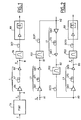
- Figures 1 and 2 show schematically and by way of example two optical transmission systems according to the invention.
- the system comprises a optical link L composed of a single section and arranged between a TX transmitter and an RX receiver.
- a source signal for example an electrical signal E modulated at NRZ format to the rhythm of a clock of period T
- the transmitter TX is able to deliver an optical signal with controlled phase S modulated at the same clock rate in PSBT format, such that detailed in the aforementioned documents.
- the RX receiver basically has a preamplifier optics followed by a photodetector.
- Connection L has an inlet end A provided to receive the signal S and an output end B, located near the RX receiver and designed to deliver a corresponding output signal R.
- the link L is mainly consisting of an LF transmission fiber and an optical emission amplifier OA disposed between TX transmitter and LF fiber.
- an optical preamplifier OA 'reception can also be provided downstream of the fiber LF.
- the output signal R would be coupled directly to the RX receiver, or possibly through a compensation element of DCF chromatic dispersion.
- a centered bandpass filter on the frequency of a signal carrier wave can also be provided upstream of the receiver, for example to extract a channel in the case of a WDM transmission or to attenuate noise outside the signal band.
- the transmission coefficient of the filter as a function of the optical frequency always has a very wide spectral width higher than the 1 / T clock frequency of modulation of signal.
- the length of the LF fiber but also compensate for the increase in attenuation which results in increasing the optical power of the signal injected into the LF fiber. Beyond a certain power, fiber is the seat of nonlinear optical phenomena (Kerr effect) important.
- FIG. 3 shows in solid lines an approximate curve of the spectrum of the transmitted signal S modulated in PSBT format.
- This spectrum which expresses the variations of the normalized power spectral density FT 2 (S) as a function of the optical frequency f corresponds to a signal PSBT of optical carrier frequency f0 and of bit period T.
- FIG. 3 also shows the curve FT 2 (R) representative of the spectrum of the received signal R in the case of a conventional link.
- the spectrum of the signal therefore undergoes a broadening during its transmission in the link, which is mainly attributed to a phase self-modulation of the signal.
- an FG optical filter is coupled to the outlet end B so as to be inserted between this end B and the RX receiver.
- the filter is calibrated to apply a reduction in sound width to signal R spectrum so as to compensate, even overcompensate, the enlargement produced in the fiber.
- Filters may be suitable for practice are typically of the Gaussian (or approaching) type and having a transfer function (which expresses variations in the filter transmission coefficient in function of the optical frequency f) centered on f0 and of spectral width at mid-height between 0.5 / T and 1.25 / T.
- this spectral width at mid-height is close to 0.75 / T.
- FIG. 4 shows a curve representative of the normalized transfer function G (f) corresponding to the latter case.
- G (f) exp [-a 2 . (F-f0) 2 .T 2 ]
- f and f0 being expressed in hertz and T in seconds, we find that a 2 is substantially equal to 4.93.
- the link is consisting of several sections.
- the case of a link with three sections is represented by the figure 2.
- the link is composed of a succession of sections L1, L2, L3.
- Each section has a constitution identical to the bond L of figure 1.
- the entry end A1 of the first section L1 is intended to receive from the transmitter TX (not shown) signal S, while output end B3 of the last section L3 is located near the receiver RX and designed to deliver a corresponding output signal R.
- the corrective optical means consist of several optical filters FG1, FG2, FG3 coupled respectively to the output ends B1, B2, B3 sections so as to be inserted respectively between these outlet ends B1, B2 and the ends A2, A3 of the following sections, except for the last filter which is inserted between the output ends B3 of the last section and the RX receiver.
- the filters FG1, FG2, FG3 will be advantageously chosen so that the function of transfer of the equivalent filter which would be formed by the cascade coupling of these filters is approximately Gaussian near f0, centered on f0, with a spectral width at mid-height between 0.5 / T and 1.25 / T.
- this spectral width at mid-height is substantially equal to 0.75 / T.
- Nb 2 a 2 , which implies for each of the filters a spectral width at half height N times greater than for the filter adapted to the case where the connection comprises a single section.
- each of the optical filters can be a filter periodic, such as a Fabry-Pérot filter, respecting the previous criteria, provided that its spectral range free expressed in frequencies is greater than 1 / T.
- the systems which have just been described are also usable for WDM transmissions of signals in format PSBT.
- the TX transmitter can then include means (not shown) to modulate and combine several signals at PSBT format carried respectively by several waves optical carriers of different optical frequencies.
- the RX receiver then includes means (not shown) to demultiplex the received signal so as to separate its different spectral components.
- a particularly simple way of implementing the invention consists in using as optical filters periodic filters with an interval ISL free spectrum equal to the offset between frequencies successive optical waves of the optical carrier multiplex.
- FIG. 5 shows the transfer function G (f) of a periodic filter adapted to multiplex transmission of channels carried by waves carriers of optical frequencies f0, f1, f2, f3, f4.
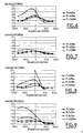
- Figures 6 to 9 show some results obtained, in the form of sensitivity curves representing variations in the sensitivity of a receiver depending on the chromatic dispersion and for different optical power values P of the transmitted signal.
- the dispersion chromatic is the so-called "residual" chromatic dispersion, i.e. the cumulative dispersion introduced by all constituent elements of the link, in particular fiber (s) transmission, dispersion compensation elements chromatic, including, where appropriate, corrective means (filters) according to the invention.
- the sensitivity which constitutes an evaluation of the quality of the transmission is defined here as the minimum value of the average optical power (in dBm) of signal to be applied to the receiver to obtain an error rate fixed at 10 -9 .
- the curves shown were obtained with connections with standard fibers of 100 km and for transmitted signals modulated in PSBT format at 10Gbit / s.
- the electro-optical modulator used is of the Mach-Zehnder type, controlled in "push-pull" mode by a filtered electrical signal by a Bessel filter with a bandwidth of 2.8 GHz.
- Figures 6 and 7 relate first to the case of a optical link consisting of a single 100 km section, such as illustrated in Figure 1.
- Figure 6 corresponds to a conventional system, that is to say without the FG filter.
- the Figure 7 corresponds to a system according to the invention, that is to say whose connection is coupled at output to the FG filter of spectral width at half height equal to 7.5 GHz or, expressed in wavelength, equal to 0.06 nm for a wavelength 1.55 ⁇ m carrier.
- Each of these figures shows three curves of sensitivity respectively for P powers of the signal supplied by the OA emission amplifier to the LF fiber from 0 dBm, 6 dBm and 12 dBm.
- Figures 8 and 9 relate to the case of a link optics consisting of three 100 km sections, such as illustrated in Figure 2.
- Figure 8 corresponds to a conventional system, i.e. without FG1 filters, FG2, FG3.
- Figure 9 corresponds to a system according to the invention, that is to say where each of the three sections is fitted with a filter FG1, FG2, FG3 of width spectral at half-height equal to 13 GHz or, expressed in wavelength, equal to 0.10 nm for a wavelength 1.55 ⁇ m carrier.
- Each of these figures shows four curves of sensitivity respectively for P powers of the signal applied to each LF1, LF2, LF3 fiber of 0 dBm, 6 dBm, 9 dBm and 12 dBm.
- the transmission system will then include elements of chromatic dispersion compensation DCF1, DCF2, DCF3 coupled respectively to sections L1, L2, L3, so that the cumulative chromatic dispersion introduced by these sections (L1, L2, L3), by the associated optical filters (FG1, FG2, FG3) and by the compensation elements of chromatic dispersion associated DCF1, DCF2, DCF3 or positive for the optical frequency f0 of the carrier wave optical of the phase-controlled optical signal S or, in the WDM multiplex transmission, for frequency mean optical wave carrier optical signals phase-controlled optics forming this multiplex.
- DCF1, DCF2, DCF3 coupled respectively to sections L1, L2, L3, so that the cumulative chromatic dispersion introduced by these sections (L1, L2, L3), by the associated optical filters (FG1, FG2, FG3) and by the compensation elements of chromatic dispersion associated DCF1, DCF2, DCF3 or positive for the optical frequency f0 of the carrier wave optical of the phase-controlled optical signal S or, in the WDM multiplex transmission,
Landscapes
- Physics & Mathematics (AREA)
- Nonlinear Science (AREA)
- Electromagnetism (AREA)
- Engineering & Computer Science (AREA)
- Computer Networks & Wireless Communication (AREA)
- Signal Processing (AREA)
- Optical Communication System (AREA)
Claims (10)
- Übertragungssystem für ein phasengesteuertes optisches Signal (S) , wobei dieses Signal im Rhythmus eines Uhrentakts mit Periode T moduliert wird, welcher aufeinanderfolgende Zeitzellen definiert, die im Signal (S) untere und obere Modulationspegel einer optischen Trägerwelle mit der optischen Frequenz f0 begrenzen, wobei das Signal (S) eine optische Phasenverschiebung im Innern jeder Zeitzelle aufweist, die einen unteren Leistungspegel begrenzt und die einer Zelle vorausgeht oder auf sie folgt, welche einen oberen Leitungspegel begrenzt, wobei das System eine optische Verbindung (L) aufweist, welche geeignet ist, das phasengesteuerte Signal (S) von einem Eingangsende (A, A1) bis zu einem Ausgangsende (B, B3) zu übertragen; hierbei ist das System dadurch gekennzeichnet, dass es optische Korrekturvorrichtungen (FG, FG1, FG2, FG3) aufweist, die mit dem Ausgangsende (B, B3) gekoppelt sind und/oder in einen oder mehrere Punkte (B1, B2) der optischen Verbindung (L) eingefügt sind, wobei diese Korrekturvorrichtungen eine optische Filterung auf das an diesem Ausgangsende (B, B3) und/oder an diesen Punkten (B1, B2) der optischen Verbindung (L) vorhandene Signal (R) anwenden, wobei diese Filterung so kalibriert wird, dass sie eine Spektrumsverbreiterung kompensiert, welche dieses phasengesteuerte Signal (S) durch Phasen-Eigenmodulation während seiner Übertragung in der optischen Verbindung (L) erfahren kann.
- Übertragungssystem nach Anspruch 1, dadurch gekennzeichnet, dass die Verbindung (L) einen einzigen Abschnitt aufweist, der mit einer Übertragungs-Lichtleitfaser (LF) ausgerüstet ist, wobei die optischen Korrekturvorrichtungen aus einem optischen Filter (FG) bestehen, der mit dem Ausgangsende (B) gekoppelt ist und eine Übertragungsfunktion (G(f)) besitzen, welche die Veränderungen in Abhängigkeit von der optischen Frequenz f ihres Übertragungskoeffizienten ausdrückt, in der Nähe von f0 ungefähr dem gaußschen Typ entsprechend, zentriert auf f0, mit einer Spektralbreite auf halber Höhe zwischen 0,5/T und 1,25/T.
- Übertragungssystem nach Anspruch 2, dadurch gekennzeichnet, dass die Spektralbreite auf halber Höhe ungefähr gleich 0,75/T ist.
- Übertragungssystem nach einem der Ansprüche 2 oder 3, dadurch gekennzeichnet, dass der optische Filter (FG) ein periodischer Filter ist, der ein in Frequenzen ausgedrücktes freies Spektralintervall größer 1/T aufweist.
- Übertragungssystem nach Anspruch 4, dadurch gekennzeichnet, dass das System dafür vorgesehen ist, einen Wellenlängenmultiplex zu übertragen, der von mehreren phasengesteuerten optischen Signalen gebildet wird, die jeweils von mehreren optischen Trägerwellen mit aufeinanderfolgenden optischen Frequenzen (F0, F1, f2, f3) getragen werden, welche eine gegebene Frequenzverschiebung aufweisen, wobei das freie Spektralintervall (ISL) gleich dieser Frequenzverschiebung ist.
- Übertragungssystem nach Anspruch 1, dadurch gekennzeichnet, dass die Verbindung N Abschnitte (L1, L2, L3) aufweist, die N Eingangsenden (A1, A2, A3) und N Ausgangsenden (B1, B2, B3) besitzen und die mit N optischen Verstärkern (OA1, OA2, OA3) ausgerüstet sind, gefolgt von N Übertragungs-Lichtleitfasern (LF1, LF2, LF3); hierbei bestehen diese optischen Korrekturvorrichtungen aus N optischen Filtern (FG1, FG2, FG3), die jeweils mit den N Ausgangsenden (B1, B2, B3) dieser Abschnitte gekoppelt sind, und zwar so, dass die Übertragungsfunktion (G(f)) des äquivalenten, durch die kaskadenartige Koppelung dieser N Filter (FG1, FG2, FG3) gebildeten Filters, welche die Änderungen in Abhängigkeit von der optischen Frequenz f ihres Übertragungskoeffizienten ausgedrückt, in der Nähe von f0 ungefähr eine gaußsche Funktion ist, zentriert auf f0, mit einer Spektralbreite auf halber Höhe zwischen 0,5/T und 1,25/T.
- Übertragungssystem nach Anspruch 6, dadurch gekennzeichnet, dass die Spektralbreite auf halber Höhe ungefähr gleich 0,75/T ist.
- Übertragungssystem nach einem der Ansprüche 6 oder 7, dadurch gekennzeichnet, dass jeder der optischen Filter (FG1, FG2, FG3) ein periodischer Filter ist, der ein in Frequenzen ausgedrücktes freies Spektralintervall größer 1/T aufweist.
- Übertragungssystem nach Anspruch 8, dadurch gekennzeichnet, dass das System für die Übertragung eines Wellenlängenmultiplex vorgesehen ist, der aus mehreren phasengesteuerten optischen Signalen gebildet wird, die jeweils von mehreren optischen Trägerwellen mit aufeinanderfolgenden optischen Frequenzen (f0-f4) getragen werden, welche eine gegebene Frequenzverschiebung aufweisen, wobei das freie Spektralintervall (ISL) gleich dieser Frequenzverschiebung ist.
- Übertragungssystem nach einem der Ansprüche 6 bis 9, dadurch gekennzeichnet, dass es Elemente zur Kompensation der chromatischen Dispersion (DCF1, DCF2, DCF3) aufweist, die jeweils mit den N Abschnitten (L1, L2, L3) in der Weise gekoppelt sind, dass die kumulierte chromatische Dispersion, die durch diese Abschnitte (L1, L2, L3), durch die dazugehörigen optischen Filter (FG1, FG2, FG3) und durch die dazugehörigen Elemente zur Kompensation der chromatischen Dispersion (DCF1, DCF2, DCF3) eingeführt wird, für die optische Frequenz (f0) der optischen Trägerwelle des phasengesteuerten optischen Signals (S) positiv ist; oder gegebenenfalls für die mittlere optische Frequenz der optischen Trägerwellen der phasengesteuerten optischen Signale, die den Multiplex bilden.
Applications Claiming Priority (2)
| Application Number | Priority Date | Filing Date | Title |
|---|---|---|---|
| FR0114604A FR2832228B1 (fr) | 2001-11-12 | 2001-11-12 | Systeme de transmission optique |
| FR0114604 | 2001-11-12 |
Publications (2)
| Publication Number | Publication Date |
|---|---|
| EP1311079A1 EP1311079A1 (de) | 2003-05-14 |
| EP1311079B1 true EP1311079B1 (de) | 2004-10-13 |
Family
ID=8869301
Family Applications (1)
| Application Number | Title | Priority Date | Filing Date |
|---|---|---|---|
| EP02292723A Expired - Lifetime EP1311079B1 (de) | 2001-11-12 | 2002-10-31 | Phasengesteuertes optisches Signalübertragungssystem |
Country Status (6)
| Country | Link |
|---|---|
| US (1) | US7123841B2 (de) |
| EP (1) | EP1311079B1 (de) |
| CN (1) | CN1419348A (de) |
| AT (1) | ATE279820T1 (de) |
| DE (1) | DE60201569T2 (de) |
| FR (1) | FR2832228B1 (de) |
Families Citing this family (3)
| Publication number | Priority date | Publication date | Assignee | Title |
|---|---|---|---|---|
| DE60030446T2 (de) * | 2000-10-27 | 2007-09-20 | Alcatel Lucent | System und Vorrichtung zum Senden von optischen Daten |
| US8238757B2 (en) * | 2007-01-18 | 2012-08-07 | Futurewei Technologies, Inc. | Method and apparatus for generating optical duobinary signals with enhanced receiver sensitivity and spectral efficiency |
| CN101971530A (zh) * | 2008-03-10 | 2011-02-09 | 住友电气工业株式会社 | 光通信系统 |
Family Cites Families (5)
| Publication number | Priority date | Publication date | Assignee | Title |
|---|---|---|---|---|
| FR2707442B1 (fr) * | 1993-07-06 | 1995-09-15 | Pirio Francis | Système de transmission sur fibre optique à compensation des distorsions en ligne. |
| FR2745451B1 (fr) * | 1996-02-23 | 1998-04-17 | Cit Alcatel | Procede de transmission optique de donnees numeriques |
| FR2781322B1 (fr) * | 1998-07-20 | 2000-09-08 | Alsthom Cge Alcatel | Dispositif d'emission de donnees optiques |
| US6430336B1 (en) * | 2000-12-18 | 2002-08-06 | Ciena Corporation | Device and method for minimizing optical channel drift |
| US6522450B2 (en) * | 2001-04-25 | 2003-02-18 | Corning Incorporated | Loss-less tunable per-channel dispersion compensator |
-
2001
- 2001-11-12 FR FR0114604A patent/FR2832228B1/fr not_active Expired - Fee Related
-
2002
- 2002-10-31 EP EP02292723A patent/EP1311079B1/de not_active Expired - Lifetime
- 2002-10-31 DE DE60201569T patent/DE60201569T2/de not_active Expired - Fee Related
- 2002-10-31 AT AT02292723T patent/ATE279820T1/de not_active IP Right Cessation
- 2002-11-04 US US10/286,827 patent/US7123841B2/en not_active Expired - Fee Related
- 2002-11-11 CN CN02150525A patent/CN1419348A/zh active Pending
Also Published As
| Publication number | Publication date |
|---|---|
| DE60201569T2 (de) | 2005-12-22 |
| CN1419348A (zh) | 2003-05-21 |
| ATE279820T1 (de) | 2004-10-15 |
| FR2832228B1 (fr) | 2004-11-19 |
| EP1311079A1 (de) | 2003-05-14 |
| FR2832228A1 (fr) | 2003-05-16 |
| US20030090770A1 (en) | 2003-05-15 |
| US7123841B2 (en) | 2006-10-17 |
| DE60201569D1 (de) | 2004-11-18 |
Similar Documents
| Publication | Publication Date | Title |
|---|---|---|
| EP0975107B1 (de) | Sendevorrichtung für optische Daten | |
| FR2737630A1 (fr) | Systeme de transmission optique a multiplexage de longueurs d'onde et dispositif d'emission utilise dans ce systeme de transmission | |
| EP0862286B1 (de) | Optische Regenerierung für faseroptische Übertragungssysteme mit nicht-Soliton Signalen | |
| FR2685835A1 (fr) | Systeme de transmission tres longue distance sur fibre optique a compensation des distorsions a la reception. | |
| EP0705504A1 (de) | Verfahren zur optischen übertragung mit vermindert dispersionsempfindlichkeit ; anordnung und verfahren zur ausführung des verfahrens | |
| FR2707442A1 (fr) | Système de transmission sur fibre optique à compensation des distorsions en ligne. | |
| EP0813097A1 (de) | Vorrichtung zur Formung von digitalen optischen Signalen und ihr Gebrauch zur Veränderung von solchen Signalen | |
| JPH11239099A (ja) | 同期偏波スクランブラを用いた光通信システム及び光受信装置 | |
| EP1617576B1 (de) | Bandbegrenztes FSK Modulationsverfahren | |
| JP3837358B2 (ja) | 光通信システム | |
| US8208816B2 (en) | Method and apparatus for dispersion mitigation in optical links | |
| EP1311079B1 (de) | Phasengesteuertes optisches Signalübertragungssystem | |
| EP0883256B1 (de) | Soliton faseroptisches Wellenlängenmultiplexiertes Übertragungssystem mit sättigbarem Absorber | |
| EP0818896A1 (de) | Optisches Datenübertragungssystem im Solitonformat | |
| EP1111819B1 (de) | Faseroptisches Übertragungssystem mit Rauschverminderung mittels nicht-linearem Offset des Signales | |
| FR2801686A1 (fr) | Processeur de signal optique | |
| EP1228589B1 (de) | Faseroptisches übertragungssystem mit optischen rz-pulsen | |
| EP0746070B1 (de) | Verfahren und Vorrichtung zur Kombination optischer Signale | |
| EP0994585B1 (de) | Leistungsausgleich in einem wellenlängenmultiplexierten optischen Übertragungssystem mit mehreren Verstärkern | |
| WO2002019574A1 (fr) | Regenerateur tout-optique pour signaux multiplexes en longueur d'onde | |
| EP0994584A1 (de) | Zwischenverstärker für ein faseroptische Fernübertragunssystem mit WDM | |
| EP1286483A2 (de) | Verbesserter optischer Modulator zur Optimierung des NRZ-modulations | |
| Lyubomirsky et al. | Experimental demonstration of a theoretically optimum optical duobinary transmission system | |
| EP2139129B1 (de) | Verfahren zur Einschränkung des nicht-linearen Phasengeräuschs eines phasenmodulierten optischen Signals mit konstanter Amplitude und entsprechende Vorrichtung | |
| EP1021004A1 (de) | Verfahren und Vorrichtung zur Stabilisierung von optischen Solitonen |
Legal Events
| Date | Code | Title | Description |
|---|---|---|---|
| PUAI | Public reference made under article 153(3) epc to a published international application that has entered the european phase |
Free format text: ORIGINAL CODE: 0009012 |
|
| AK | Designated contracting states |
Designated state(s): AT BE BG CH CY CZ DE DK EE ES FI FR GB GR IE IT LI LU MC NL PT SE SK TR |
|
| AX | Request for extension of the european patent |
Extension state: AL LT LV MK RO SI |
|
| 17P | Request for examination filed |
Effective date: 20031114 |
|
| AKX | Designation fees paid |
Designated state(s): AT BE BG CH CY CZ DE DK EE ES FI FR GB GR IE IT LI LU MC NL PT SE SK TR |
|
| GRAP | Despatch of communication of intention to grant a patent |
Free format text: ORIGINAL CODE: EPIDOSNIGR1 |
|
| GRAS | Grant fee paid |
Free format text: ORIGINAL CODE: EPIDOSNIGR3 |
|
| GRAA | (expected) grant |
Free format text: ORIGINAL CODE: 0009210 |
|
| AK | Designated contracting states |
Kind code of ref document: B1 Designated state(s): AT BE BG CH CY CZ DE DK EE ES FI FR GB GR IE IT LI LU MC NL PT SE SK TR |
|
| PG25 | Lapsed in a contracting state [announced via postgrant information from national office to epo] |
Ref country code: SK Free format text: LAPSE BECAUSE OF FAILURE TO SUBMIT A TRANSLATION OF THE DESCRIPTION OR TO PAY THE FEE WITHIN THE PRESCRIBED TIME-LIMIT Effective date: 20041013 Ref country code: BG Free format text: LAPSE BECAUSE OF FAILURE TO SUBMIT A TRANSLATION OF THE DESCRIPTION OR TO PAY THE FEE WITHIN THE PRESCRIBED TIME-LIMIT Effective date: 20041013 Ref country code: TR Free format text: LAPSE BECAUSE OF FAILURE TO SUBMIT A TRANSLATION OF THE DESCRIPTION OR TO PAY THE FEE WITHIN THE PRESCRIBED TIME-LIMIT Effective date: 20041013 Ref country code: CY Free format text: LAPSE BECAUSE OF FAILURE TO SUBMIT A TRANSLATION OF THE DESCRIPTION OR TO PAY THE FEE WITHIN THE PRESCRIBED TIME-LIMIT Effective date: 20041013 Ref country code: FI Free format text: LAPSE BECAUSE OF FAILURE TO SUBMIT A TRANSLATION OF THE DESCRIPTION OR TO PAY THE FEE WITHIN THE PRESCRIBED TIME-LIMIT Effective date: 20041013 Ref country code: SE Free format text: LAPSE BECAUSE OF FAILURE TO SUBMIT A TRANSLATION OF THE DESCRIPTION OR TO PAY THE FEE WITHIN THE PRESCRIBED TIME-LIMIT Effective date: 20041013 Ref country code: IE Free format text: LAPSE BECAUSE OF FAILURE TO SUBMIT A TRANSLATION OF THE DESCRIPTION OR TO PAY THE FEE WITHIN THE PRESCRIBED TIME-LIMIT Effective date: 20041013 Ref country code: NL Free format text: LAPSE BECAUSE OF FAILURE TO SUBMIT A TRANSLATION OF THE DESCRIPTION OR TO PAY THE FEE WITHIN THE PRESCRIBED TIME-LIMIT Effective date: 20041013 Ref country code: EE Free format text: LAPSE BECAUSE OF FAILURE TO SUBMIT A TRANSLATION OF THE DESCRIPTION OR TO PAY THE FEE WITHIN THE PRESCRIBED TIME-LIMIT Effective date: 20041013 Ref country code: AT Free format text: LAPSE BECAUSE OF FAILURE TO SUBMIT A TRANSLATION OF THE DESCRIPTION OR TO PAY THE FEE WITHIN THE PRESCRIBED TIME-LIMIT Effective date: 20041013 Ref country code: CZ Free format text: LAPSE BECAUSE OF FAILURE TO SUBMIT A TRANSLATION OF THE DESCRIPTION OR TO PAY THE FEE WITHIN THE PRESCRIBED TIME-LIMIT Effective date: 20041013 |
|
| REG | Reference to a national code |
Ref country code: GB Ref legal event code: FG4D Free format text: NOT ENGLISH |
|
| REG | Reference to a national code |
Ref country code: CH Ref legal event code: EP |
|
| PG25 | Lapsed in a contracting state [announced via postgrant information from national office to epo] |
Ref country code: BE Free format text: LAPSE BECAUSE OF NON-PAYMENT OF DUE FEES Effective date: 20041031 Ref country code: LU Free format text: LAPSE BECAUSE OF NON-PAYMENT OF DUE FEES Effective date: 20041031 Ref country code: MC Free format text: LAPSE BECAUSE OF NON-PAYMENT OF DUE FEES Effective date: 20041031 |
|
| GBT | Gb: translation of ep patent filed (gb section 77(6)(a)/1977) |
Effective date: 20041013 |
|
| REG | Reference to a national code |
Ref country code: IE Ref legal event code: FG4D Free format text: FRENCH |
|
| REF | Corresponds to: |
Ref document number: 60201569 Country of ref document: DE Date of ref document: 20041118 Kind code of ref document: P |
|
| PG25 | Lapsed in a contracting state [announced via postgrant information from national office to epo] |
Ref country code: DK Free format text: LAPSE BECAUSE OF FAILURE TO SUBMIT A TRANSLATION OF THE DESCRIPTION OR TO PAY THE FEE WITHIN THE PRESCRIBED TIME-LIMIT Effective date: 20050113 Ref country code: GR Free format text: LAPSE BECAUSE OF FAILURE TO SUBMIT A TRANSLATION OF THE DESCRIPTION OR TO PAY THE FEE WITHIN THE PRESCRIBED TIME-LIMIT Effective date: 20050113 |
|
| PG25 | Lapsed in a contracting state [announced via postgrant information from national office to epo] |
Ref country code: ES Free format text: LAPSE BECAUSE OF FAILURE TO SUBMIT A TRANSLATION OF THE DESCRIPTION OR TO PAY THE FEE WITHIN THE PRESCRIBED TIME-LIMIT Effective date: 20050124 |
|
| NLV1 | Nl: lapsed or annulled due to failure to fulfill the requirements of art. 29p and 29m of the patents act | ||
| BERE | Be: lapsed |
Owner name: ALCATEL Effective date: 20041031 |
|
| REG | Reference to a national code |
Ref country code: IE Ref legal event code: FD4D |
|
| PLBE | No opposition filed within time limit |
Free format text: ORIGINAL CODE: 0009261 |
|
| STAA | Information on the status of an ep patent application or granted ep patent |
Free format text: STATUS: NO OPPOSITION FILED WITHIN TIME LIMIT |
|
| 26N | No opposition filed |
Effective date: 20050714 |
|
| PG25 | Lapsed in a contracting state [announced via postgrant information from national office to epo] |
Ref country code: LI Free format text: LAPSE BECAUSE OF NON-PAYMENT OF DUE FEES Effective date: 20061031 Ref country code: CH Free format text: LAPSE BECAUSE OF NON-PAYMENT OF DUE FEES Effective date: 20061031 |
|
| REG | Reference to a national code |
Ref country code: CH Ref legal event code: PL |
|
| REG | Reference to a national code |
Ref country code: FR Ref legal event code: CD |
|
| BERE | Be: lapsed |
Owner name: *ALCATEL Effective date: 20041031 |
|
| PG25 | Lapsed in a contracting state [announced via postgrant information from national office to epo] |
Ref country code: PT Free format text: LAPSE BECAUSE OF NON-PAYMENT OF DUE FEES Effective date: 20050313 |
|
| PGFP | Annual fee paid to national office [announced via postgrant information from national office to epo] |
Ref country code: DE Payment date: 20081022 Year of fee payment: 7 |
|
| PGFP | Annual fee paid to national office [announced via postgrant information from national office to epo] |
Ref country code: IT Payment date: 20081022 Year of fee payment: 7 |
|
| PGFP | Annual fee paid to national office [announced via postgrant information from national office to epo] |
Ref country code: FR Payment date: 20081014 Year of fee payment: 7 |
|
| PGFP | Annual fee paid to national office [announced via postgrant information from national office to epo] |
Ref country code: GB Payment date: 20081021 Year of fee payment: 7 |
|
| REG | Reference to a national code |
Ref country code: FR Ref legal event code: ST Effective date: 20100630 |
|
| PG25 | Lapsed in a contracting state [announced via postgrant information from national office to epo] |
Ref country code: FR Free format text: LAPSE BECAUSE OF NON-PAYMENT OF DUE FEES Effective date: 20091102 Ref country code: DE Free format text: LAPSE BECAUSE OF NON-PAYMENT OF DUE FEES Effective date: 20100501 |
|
| PG25 | Lapsed in a contracting state [announced via postgrant information from national office to epo] |
Ref country code: GB Free format text: LAPSE BECAUSE OF NON-PAYMENT OF DUE FEES Effective date: 20091031 |
|
| PG25 | Lapsed in a contracting state [announced via postgrant information from national office to epo] |
Ref country code: IT Free format text: LAPSE BECAUSE OF NON-PAYMENT OF DUE FEES Effective date: 20091031 |