EP1311761B1 - Blasendetektor und blasenfänger für ein flüssigkeitsfördersystem - Google Patents
Blasendetektor und blasenfänger für ein flüssigkeitsfördersystem Download PDFInfo
- Publication number
- EP1311761B1 EP1311761B1 EP01968057A EP01968057A EP1311761B1 EP 1311761 B1 EP1311761 B1 EP 1311761B1 EP 01968057 A EP01968057 A EP 01968057A EP 01968057 A EP01968057 A EP 01968057A EP 1311761 B1 EP1311761 B1 EP 1311761B1
- Authority
- EP
- European Patent Office
- Prior art keywords
- compression
- volume
- fluid
- pump head
- pump
- Prior art date
- Legal status (The legal status is an assumption and is not a legal conclusion. Google has not performed a legal analysis and makes no representation as to the accuracy of the status listed.)
- Expired - Lifetime
Links
- 238000011084 recovery Methods 0.000 title claims abstract description 54
- 238000005086 pumping Methods 0.000 title claims abstract description 37
- 238000001514 detection method Methods 0.000 title claims abstract description 34
- 239000007788 liquid Substances 0.000 title abstract description 24
- 230000006835 compression Effects 0.000 claims abstract description 81
- 238000007906 compression Methods 0.000 claims abstract description 81
- 239000012530 fluid Substances 0.000 claims abstract description 60
- 230000007246 mechanism Effects 0.000 claims abstract description 52
- 230000006837 decompression Effects 0.000 claims abstract description 42
- 238000012544 monitoring process Methods 0.000 claims description 17
- 238000000034 method Methods 0.000 claims description 12
- 239000007789 gas Substances 0.000 abstract description 47
- 230000009977 dual effect Effects 0.000 abstract description 11
- 239000003480 eluent Substances 0.000 abstract description 8
- 239000011877 solvent mixture Substances 0.000 abstract description 2
- 239000002904 solvent Substances 0.000 description 35
- 238000010926 purge Methods 0.000 description 17
- 230000007704 transition Effects 0.000 description 15
- 239000000203 mixture Substances 0.000 description 11
- 238000010586 diagram Methods 0.000 description 10
- 238000004128 high performance liquid chromatography Methods 0.000 description 8
- 239000000243 solution Substances 0.000 description 7
- 239000012071 phase Substances 0.000 description 6
- 238000004587 chromatography analysis Methods 0.000 description 5
- 230000000694 effects Effects 0.000 description 5
- 238000002156 mixing Methods 0.000 description 5
- 230000003750 conditioning effect Effects 0.000 description 4
- 238000002347 injection Methods 0.000 description 4
- 239000007924 injection Substances 0.000 description 4
- 230000010349 pulsation Effects 0.000 description 4
- 238000000926 separation method Methods 0.000 description 4
- 238000010521 absorption reaction Methods 0.000 description 3
- 230000009471 action Effects 0.000 description 3
- 230000001934 delay Effects 0.000 description 3
- 238000013461 design Methods 0.000 description 3
- 230000002411 adverse Effects 0.000 description 2
- 230000007812 deficiency Effects 0.000 description 2
- 230000001627 detrimental effect Effects 0.000 description 2
- 238000007599 discharging Methods 0.000 description 2
- 230000001771 impaired effect Effects 0.000 description 2
- 238000007726 management method Methods 0.000 description 2
- 230000004044 response Effects 0.000 description 2
- 230000035945 sensitivity Effects 0.000 description 2
- 230000003213 activating effect Effects 0.000 description 1
- 238000007792 addition Methods 0.000 description 1
- 150000001875 compounds Chemical class 0.000 description 1
- 238000012937 correction Methods 0.000 description 1
- 238000007872 degassing Methods 0.000 description 1
- 238000006073 displacement reaction Methods 0.000 description 1
- HDDSHPAODJUKPD-UHFFFAOYSA-N fenbendazole Chemical compound C1=C2NC(NC(=O)OC)=NC2=CC=C1SC1=CC=CC=C1 HDDSHPAODJUKPD-UHFFFAOYSA-N 0.000 description 1
- 238000007667 floating Methods 0.000 description 1
- 239000003102 growth factor Substances 0.000 description 1
- 230000000977 initiatory effect Effects 0.000 description 1
- 238000004811 liquid chromatography Methods 0.000 description 1
- 239000007791 liquid phase Substances 0.000 description 1
- 230000007774 longterm Effects 0.000 description 1
- 238000005259 measurement Methods 0.000 description 1
- 230000000116 mitigating effect Effects 0.000 description 1
- 238000010943 off-gassing Methods 0.000 description 1
- 239000013618 particulate matter Substances 0.000 description 1
- 229940092174 safe-guard Drugs 0.000 description 1
- 230000007480 spreading Effects 0.000 description 1
- 230000006641 stabilisation Effects 0.000 description 1
- 238000011105 stabilization Methods 0.000 description 1
- 230000001360 synchronised effect Effects 0.000 description 1
- 230000001960 triggered effect Effects 0.000 description 1
Images


Classifications
-
- F—MECHANICAL ENGINEERING; LIGHTING; HEATING; WEAPONS; BLASTING
- F04—POSITIVE - DISPLACEMENT MACHINES FOR LIQUIDS; PUMPS FOR LIQUIDS OR ELASTIC FLUIDS
- F04B—POSITIVE-DISPLACEMENT MACHINES FOR LIQUIDS; PUMPS
- F04B49/00—Control, e.g. of pump delivery, or pump pressure of, or safety measures for, machines, pumps, or pumping installations, not otherwise provided for, or of interest apart from, groups F04B1/00 - F04B47/00
- F04B49/06—Control using electricity
- F04B49/065—Control using electricity and making use of computers
-
- F—MECHANICAL ENGINEERING; LIGHTING; HEATING; WEAPONS; BLASTING
- F04—POSITIVE - DISPLACEMENT MACHINES FOR LIQUIDS; PUMPS FOR LIQUIDS OR ELASTIC FLUIDS
- F04B—POSITIVE-DISPLACEMENT MACHINES FOR LIQUIDS; PUMPS
- F04B49/00—Control, e.g. of pump delivery, or pump pressure of, or safety measures for, machines, pumps, or pumping installations, not otherwise provided for, or of interest apart from, groups F04B1/00 - F04B47/00
- F04B49/06—Control using electricity
-
- F—MECHANICAL ENGINEERING; LIGHTING; HEATING; WEAPONS; BLASTING
- F04—POSITIVE - DISPLACEMENT MACHINES FOR LIQUIDS; PUMPS FOR LIQUIDS OR ELASTIC FLUIDS
- F04B—POSITIVE-DISPLACEMENT MACHINES FOR LIQUIDS; PUMPS
- F04B53/00—Component parts, details or accessories not provided for in, or of interest apart from, groups F04B1/00 - F04B23/00 or F04B39/00 - F04B47/00
- F04B53/06—Venting
-
- F—MECHANICAL ENGINEERING; LIGHTING; HEATING; WEAPONS; BLASTING
- F04—POSITIVE - DISPLACEMENT MACHINES FOR LIQUIDS; PUMPS FOR LIQUIDS OR ELASTIC FLUIDS
- F04B—POSITIVE-DISPLACEMENT MACHINES FOR LIQUIDS; PUMPS
- F04B2201/00—Pump parameters
- F04B2201/02—Piston parameters
- F04B2201/0201—Position of the piston
-
- F—MECHANICAL ENGINEERING; LIGHTING; HEATING; WEAPONS; BLASTING
- F04—POSITIVE - DISPLACEMENT MACHINES FOR LIQUIDS; PUMPS FOR LIQUIDS OR ELASTIC FLUIDS
- F04B—POSITIVE-DISPLACEMENT MACHINES FOR LIQUIDS; PUMPS
- F04B2201/00—Pump parameters
- F04B2201/02—Piston parameters
- F04B2201/0206—Length of piston stroke
-
- F—MECHANICAL ENGINEERING; LIGHTING; HEATING; WEAPONS; BLASTING
- F04—POSITIVE - DISPLACEMENT MACHINES FOR LIQUIDS; PUMPS FOR LIQUIDS OR ELASTIC FLUIDS
- F04B—POSITIVE-DISPLACEMENT MACHINES FOR LIQUIDS; PUMPS
- F04B2205/00—Fluid parameters
- F04B2205/01—Pressure before the pump inlet
-
- F—MECHANICAL ENGINEERING; LIGHTING; HEATING; WEAPONS; BLASTING
- F04—POSITIVE - DISPLACEMENT MACHINES FOR LIQUIDS; PUMPS FOR LIQUIDS OR ELASTIC FLUIDS
- F04B—POSITIVE-DISPLACEMENT MACHINES FOR LIQUIDS; PUMPS
- F04B2205/00—Fluid parameters
- F04B2205/05—Pressure after the pump outlet
-
- F—MECHANICAL ENGINEERING; LIGHTING; HEATING; WEAPONS; BLASTING
- F04—POSITIVE - DISPLACEMENT MACHINES FOR LIQUIDS; PUMPS FOR LIQUIDS OR ELASTIC FLUIDS
- F04B—POSITIVE-DISPLACEMENT MACHINES FOR LIQUIDS; PUMPS
- F04B2205/00—Fluid parameters
- F04B2205/50—Presence of foreign matter in the fluid
- F04B2205/503—Presence of foreign matter in the fluid of gas in a liquid flow, e.g. gas bubbles
Definitions
- the present invention relates to liquid pumps, and more particularly to a method and apparatus for detecting and recovering from gas bubbles in a liquid stream being pumped by the liquid pump.
- High-pressure pumping systems are known for delivering liquid at high pressure. Such a system is described in U.S. Patent No. 4,883,409 ("the '409 patent”).
- the ⁇ 409 patent describes a pumping apparatus for delivering liquid at a high pressure, such as for high performance liquid chromatography (“HPLC") applications.
- the pumping apparatus comprises two pistons which reciprocate in respective pump chambers.
- the pistons and pump chambers are connected “serially" in that the output of the first pump chamber is connected via a valve to the-input of the second pump chamber.
- the pistons are driven by linear drives, e.g., ball-screw spindles, and are synchronized so that a first or primary pump head receives its fluid intake at atmospheric or ambient pressure and compresses the intake, or puts it under pressure to a point, just prior to delivering the fluid to the second or accumulator pump head which has a high pressure interconnection with the primary pump head and virtually always receives pressurized fluid.
- the stroke volume displaced by the respective piston is freely adjustable during a controlled stroke cycle. Control circuitry is operative to reduce stroke volume at reduced flow rates, leading to reduced pulsations in the outflow of the pumping apparatus.
- the pumping system includes a control means and mechanisms to vary stroke length or volume, and stroke frequency.
- the control means is operative to adjust the stroke lengths of the pistons between their top dead center and their bottom dead center, respectively, permitting an adjustment of the amounts of liquid displaced by the first and second piston, respectively, during a pump cycle such that pulsations in the flow of the liquid delivered to the output of the pumping apparatus are reduced.
- At least one system known in the art identifies problems and includes mechanisms that attempt to address the problems associated with gas in the liquid stream.
- U.S. Patent No. 5,393,434 (“the '434 patent”) discloses that gas liberated due to reduced pressures during the inlet phase of operation of a pressurized pumping system can accumulate in the pumping chamber and will not be expelled through the outlet because of the back pressure present. Consequently, the pump will stop pumping liquid when the trapped gas remains in the system.
- Other problems are produced by typical hard seat check valves which can be propped open by particulate matter causing leaks.
- ordinary inlet valves in known systems are opened on an inlet stroke by suction, which contributes to undesirable gas generation from the liquid being pumped.
- a liquid chromatography system including a liquid pump having a pumping chamber, an inlet port, an outlet port, and a purge port, all communicating with the pumping chamber.
- a purge valve is connected to the purge port and is used to purge gas from the system.
- a disclosed method of operation of the system includes monitoring the pumping performance of the liquid pump to detect the presence of air in the pumping chamber, opening the purge valve; and producing a forward stroke of the piston to discharge the detected air through the purge valve. It is asserted in the '434 patent that purging of the pumping chamber will quickly correct faulty pump performance resulting from air trapped in the liquid phase. The pumping performance is monitored by monitoring the pressure in the pumping chamber, as it is asserted that pumping chamber pressure can indicate the presence of trapped air.
- each liquid pump has a pumping chamber, an inlet valve for receiving liquid, an outlet valve for discharging liquid to a separation column, a piston for drawing liquid through the inlet valve during a backstroke and for discharging liquid through the outlet valve during a forward stroke, and a pressure sensor for sensing the pressure in the pumping chamber.
- the method of operating such an apparatus involves monitoring the pressure in the pumping chamber with the pressure sensor during the forward stroke of the piston to detect the presence of air in the pumping chamber; determining the deficiency in liquid flow produced by the pump because of the detected air in the pumping chamber; and adjusting the operation of the pump to compensate for the deficiency.
- Adjusting pump operation effects desired pump performance by compensating the length of the pump's forward stroke.
- the adjusting step may include adjusting the speed of the forward stroke of the piston, or adjusting the speed of the backstroke of the piston.
- the monitoring is performed during an early portion of the forward stroke. Early stroke monitoring facilitates the desired adjustment of pump operation.
- monitoring is effected with a first pressure sensor which monitors the pressure in the first pumping chamber to detect an end of the forward stroke by the first piston.
- Forward stroke of the second piston is initiated in response to the monitoring of the pressure in the first pumping chamber.
- a second pressure sensor senses the pressure in the second pumping chamber to detect an end of the forward stroke by the second piston.
- the forward stroke of the first piston follows in response to the sensing of the pressure in the second pumping chamber. Accordingly, controlled parallel pump operation is effected.
- Uniform system pressure in the parallel implementation is effected by determining system pressure in the separation system and accordingly initiating the forward stroke of the first piston to provide the system pressure in the first pumping chamber at the end of the forward stroke by the second piston.
- the forward stroke of the second piston is initiated, at the end of the forward stroke of the first piston, to provide the system pressure in the second pumping chamber.
- the forward stroke of the second piston is initiated at the end of the forward stroke of the first piston, and the forward stroke of the first piston is initiated at the end of the forward stroke of the second piston This synchronizes operation of the parallel pump.
- Parallel pumps such as disclosed in the '434 patent have inherent disadvantages.
- Parallel pump configurations which by definition alternate delivery between pump heads, tend to have higher levels of unswept volumes Dead or unswept volumes remain undelivered, and during gradient operation the unswept volume is delivered out of order, i.e. after delivery of the alternate pump head volume, resulting in compositional ripple and/or inaccurate chromatographic peaks.
- the mechanism effected in the '434 patent disadvantageously includes a spring loaded outlet check valve which requires additional mechanical parts to address problems associated with gas in the liquid stream.
- the outlet check valve prevents fluid passage from the pump outlet to a pulse dampener when gas is trapped in the pump chamber(s).
- a separate purge valve is activated to facilitate escape of the gas.
- the purge valve is opened, i.e. turned on, and the gas bubble is expelled.
- the check valves in the form of the check valves and purge valves, represent unnecessary mechanical complexity and cost in the system according to the ⁇ 434 patent
- the check valves as discussed in the '434 patent, present an opportunity for gas to enter the system and/or for leaks to develop. Failure of the mechanical check valves to expel gas from the system can result in the loss of prime of the pumps which will shut the system down.
- the purge valve and inlet check valve have unswept volumes or flow areas which will disadvantageously contribute to band spreading or broadening of chromatographic peaks.
- the increased volume in the pump heads due to check valves and purge valves leads to lower compression ratios for pumps according to the '434 patent design, which increases the difficulty in expelling bubbles.
- U.S. Patent No. 5,823,747 to Ciavarini et al. provides, a serial, dual piston high pressure fluid pumping system that overcomes the difficulties of gas in the fluid stream without the need for added mechanical valves or fluid paths.
- a bubble detection and recovery mechanism monitors compression and decompression volumes, and overall system delivery pressure of a serially configured dual pump head pump.
- Bubble detection is effected by sensing a ratio of compression to decompression volume and determining if the ratio exceeds an empirical threshold that suggests the ratio of gas-to-liquid content of eluent or fluid in the system is beyond the pump's ability to accurately meter a solvent fixture.
- the magnitude of the ratio of compression to decompression volume indicates that either the intake stroke has a bubble or that the eluent has a higher-than-normal gas content.
- the very high stroke volume used to expel gas according to the method of U.S. Patent No. 5,823,747 may differ substantially from the optimal stroke volume for given flow settings under normal conditions. Therefore, transition to the very high stroke volume may cause perturbation in the desired constant flow and composition.
- the present invention provides a method of detecting gas in a fluid transported through a fluid delivery system according to claim 1.
- the present invention provides a serial, dual piston high pressure fluid delivery or pumping system according to claim 2 that automatically apportions the amount of piston travel necessary to keep gasses compressed into solution and maintain steady flow.
- the compression phase of a dual piston, high pressure fluid pumping system is optimized to maintain steady flow delivery under widely changing quantities of gas intrained in the fluid stream.
- the method of the invention continuously monitors the amount of stroke volume required to compress the fluid during each pump cycle and automatically apportions the correct amount of piston travel necessary to keep the gasses compressed into solution. Available portions of delivery stroke is traded off in favor of the compression phase only when it is needed under conditions of high gas loading. Such conditions typically occur while starting the system before solvent degassing is underway or whenever a bubble comes out of the solution. Under lighter gas loading conditions, the method returns the excess portion of the compression stroke back to the delivery stroke, thereby mitigating the effects of outgassing.
- a solvent delivery system for HPLC which can automatically recover from a potential loss of prime during many hours of unattended chromatography runs of hundreds of injections.
- the detection of a bubble can be logged and recorded during each HPLC injection run, .to provide a cross-check mechanism to notify the user that chromatography in a given run may be impaired. If the magnitude of a bubble or the degree of gas absorption by the solvent is not too severe, then automatic recovery can maintain acceptable chromatographic results under most typical and adverse external influences of solvent conditioning. Thus solvent conditioning at the input may be minimized.
- Initial detection of bubbles or gas is qualified using system delivery pressure to substantially prevent false triggering of the recovery sequence whenever the pump is delivering flow in a non-chromatographic context, e.g.
- Bubble detection according to the invention permits operation at short piston stroke lengths which minimizes delay volume and compositional ripple with low gas compression ratios. The bubble detection desensitizes operational sensitivity to low gas compression ratios. Continuous automatic adjustment of piston stroke volume during gas expulsion phases minimizes perturbation in flow and composition.
- a bubble detection and recovery mechanism detects the presence of a bubble or significant amounts of gas in-a fluid stream and performs a recovery sequence to enhance the pump's ability to expel a bubble or solvent/fluid stream having a significant gas content
- the bubble detection and recovery mechanisms is implemented in a solvent delivery pump system, such as is typical in High Pressure Liquid Chromatography (HPLC) applications.
- HPLC High Pressure Liquid Chromatography
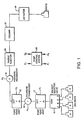
- the apparatus in which the bubble detection and recovery mechanism is implemented is a solvent delivery pump system, such as illustrated in Fig. 1 , designed to meter multiple solvents and deliver a desired mixture at a desired flow rate for the purpose of performing chromatography-separations of sample compounds.
- solvent mixing is performed on a low-pressure inlet side of the pump.
- Up to four different eluents i.e. solvents
- A, B, C, D are available for mixing in selected compositions, as known in the art, using a known solvent selector valve 10.
- the solvent selector valve 10 performs low pressure mixing of the solvents A, B, C, D, in any combination of the four eluents at atmospheric pressure.
- the outlet of the solvent selector valve 10 is connected to a pump head assembly 12 of a primary pump, which receives the mixed composition of solvents at ambient pressure and effects initial pressurization of the fluids input to the system.
- the primary pump head 12 in this illustrative embodiment (and likewise an accumulator pump head as discussed hereinafter) is a pump head that has features as described in U.S. Patent 5,788,465 filed February 23,1996 .
- the pump head 12 is generally comprised of a piston configured to reciprocate in a piston chamber, an inlet check valve, and a motor and drive mechanism (none of which are shown in Fig. 1 ).
- the pump heads are also configured with a motor shaft encoder that ultimately provides measurement of the position of the reciprocating plunger with respect to a reference and outputs a signal indicative of the same.
- the primary pump head 12 is the low pressure side of the pump, because its intake is at atmospheric pressure during the pump cycle.
- the primary pump head 12 is used to pressurize the solvent input and bring it up to the desired system pressure.
- a pressure transducer 14 is used at the output of the primary pump head 12 to determine the pressure of fluid output.
- the primary pump head 12 works in conjunction with an accumulator pump head 16 to effect a serial, dual piston pump implementation.
- the accumulator pump head is maintaining system delivery, delivering solvent at system pressure.
- the primary pump head 12 is also brought up to system pressure just prior to it delivering fluid to the system via the accumulator pump head 16, by driving towards top dead center up to a maximum percentage of the working stroke, referred to as a pre-compression limit or constraint.
- the accumulator is receiving and storing fluid for the next delivery cycle.
- the outlet of the primary pump head 12 is connected to the pressure transducer 14, and the outlet of the pressure transducer 14 is connected to the accumulator pump head 16, which is the high pressure side of the pump.
- the outlet of the accumulator pump head 16 is connected to a second pressure transducer 18 which registers system delivery pressure.
- the outlet of the transducer is connected to the sampler/injector 20 which is in turn connected to a separation column 22 and detector 24, as would be understood by those skilled in the art.
- a pump control system 26 receives encoder signals E1, E2 and pressure signals P1, P2 and converts them into meaningful information used for control and bubble detection.
- the pump control system comprises a microprocessor based system and a digital signal processor, which collaboratively perform the functions of flow and composition control, and motion control respectively, detailed description of which is beyond the scope of the present disclosure.
- the pump control system 26 uses the encoder signals E1, E2 and the pressure signals P1, P2, to generate a compression volume signal 32 and decompression volume signal 34 and a system delivery pressure signal 36.
- the pump control system 26 makes available to the bubble detection and recovery mechanism, compression volume 32, decompression volume 34, and system delivery pressure 36 obtained via the pressure transducer 18.
- the pump control system determines the amount of decompression volume 32 by monitoring the pressure transducer 14 and the encoder signal E1 during the intake stroke.
- the decompression volume is obtained by noting the plunger position at which the signal from the pressure transducer 14 reaches a value that represents atmospheric pressure.
- the pump control system determines the amount of compression volume 32 by monitoring the signal from the pressure transducer 14 and encoder signal E1 during the pre-compression stroke, prior to delivering to the accumulator pump head 16.
- the compression volume is obtained by noting the amount of plunger travel, from the encoder signal E1, that it takes for the signal from the pressure transducer 14 to reach the equivalent Value of the signal from the second pressure transducer 18, which is the system delivery pressure 36.
- the compression and decompression volume signals 32, 34 and the system delivery pressure signal 36 are issued to the bubble detection and recovery mechanism 30 according to the invention.
- the bubble detection and recovery mechanism is generally a state machine that operates in tandem with the pump control system which, as generally understood in the art, controls both the pump's flow delivery and fluid composition.
- the bubble detection and recovery mechanism 30 provides its state value 38 to the pump controller 26.
- the system controller 26 monitors the state value and only initiates a bubble recovery stroke when it sees the state in Recovery mode.
- the pump control system 26 and the bubble detection and recovery mechanism 30 operate independently of one another.
- a state transition diagram of the bubble detection and recovery mechanism is illustrated in Fig. 3 .
- the state transition diagram represents the internal behavior of the bubble detection and recovery mechanism 30.
- a compression to decompression volume ratio parameter trips or enables bubble detection when the ratio exceeds an empirically derived threshold.
- the ratio of compression to decompression volume exceeding an empirical threshold indicates that the ratio of gas-to-liquid content of the eluent is beyond the pump's ability to accurately meter a solvent mixture.
- the extent to which the ratio exceeds a predetermined ratio suggests that either the intake stroke has a bubble or that the eluent has a higher-than-normal gas content.
- the state machine implementing the bubble detection and recovery mechanism 30 includes the following states:
- the pump control system monitors the state of the bubble mechanism while maintaining the desired flow rate and solvent composition settings and only modifies its behavior whenever it sees the bubble mechanism in the state Recovery. If the magnitude of a bubble or the degree of gas absorption by the solvent is not too severe, then automatic recovery, as described, can maintain acceptable chromatographic results under the most typical and adverse external influences of solvent conditioning. In all other states, the pump control system maintains the preset working stroke parameters.
- the bubble mechanism As illustrated in the state transition diagram of Fig. 3 , the bubble mechanism, once enabled, remains idle in its Armed state while it monitors for the presence of a bubble. While in the Armed state, the bubble mechanism monitors the compression and decompression volumes obtained each pump cycle from the pump control system. If the ratio of compression-to-decompression volumes exceeds an empirically-derived threshold limit R 1 (in this illustrative embodiment the limit is approximately 1.0-2.0), and the system delivery pressure exceeds a preset minimum threshold P1 (in this embodiment approximately 650 psi), then the mechanism transitions to the Detect state.
- R 1 empirically-derived threshold limit
- P1 in this embodiment approximately 650 psi
- the mechanism blindly delays for a preset number of N 1 pump cycles (approximately equal to 6) to ensure that the bubble is sufficiently large to warrant a recovery sequence.
- N 1 pump cycles the ratio of compression-to-decompression volumes is checked a second time. If the threshold R 1 is found to be violated or exceeded, then the mechanism considers a bubble as being detected, otherwise the bubble is considered too small in magnitude and the mechanism transitions back to the Armed state.
- the pressure threshold of P 1 is not used to qualify the second violation of R 1 , in case the magnitude of the bubble is sufficiently large to have collapsed system delivery pressure. This ensures that bubble recovery will be performed to avoid a loss of prime condition.
- the solvent delivery system can automatically recover from a potential loss of prime during many hours of unattended chromatography runs of hundreds of injections.
- the action taken on egress from the Detect state when the mechanism has declared a detected bubble is contingent on a user-configurable system-level option for bubble detect.
- the user may elect to either ignore, log only, or log and recover. If the option is configured to ignore, then the mechanism returns back to the Armed state. If the option is configured to log only, then a bubble detect message is logged to alert the user that the chromatogram may have been affected, before returning to the Armed state. If the option is configured to log and recover, then the mechanism logs the bubble detect message and transitions to the Recovery state, which initiates the recovery sequence. Accordingly, the detection of a bubble can be logged and recorded during each HPLC injection run, to notify the user that chromatography may be impaired.
- the bubble mechanism remains in the Recovery state for a fixed duration of a preset number of pump cycles N 2 (in this embodiment set to 10) to allow the pump controller a sufficient number of strokes to clear the bubble using the larger bubble recovery stroke. Meanwhile, as soon as the pump controller recognizes that the bubble mechanism has entered the Recovery state, it changes its cycle scheduling at the next intake stroke to use the larger bubble recovery stroke and constrains the amount of stroke travel normally allocated for decompression and pre-compression. These two actions allow the pump to attain a sufficient compression ratio necessary to expel solvent that has absorbed a considerable amount of gas. The pump controller continues to operate under the bubble recovery stroke parameters until the bubble mechanism transitions out of its Recovery state.
- N 2 in this embodiment set to 10
- the bubble mechanism transitions into the state Restoring Stroke. This state is necessary, because the pump controller can not instantaneously transition between the normal operating stroke and the bubble recovery stroke. Depending on the operational stroke, it can take up to 4 pump cycles (N) while in the Recovery state to shift into the bubble recovery stroke. On entry into the Recovery state, the bubble mechanism keeps track of how many pump cycles it took for the pump controller to shift up to the bubble recovery stroke. It uses this count later to count down in the Restoring Stroke state before it begins its stabilization delay in the Rearming Delay state. The state transition from Restoring Stroke to Rearming Delay is detected by the pump controller as a signal to return back to the normal operating stroke parameters.
- the bubble mechanism remains in the Rearming Delay state for a fixed duration of a preset number of pump cycles to allow the pump sufficient time to restabilize.
- N 3 in this embodiment set to 6
- the bubble mechanism completes its recovery sequence by returning back to the Armed state.
- the compression ratio is checked again as described hereinbefore.
- the Off and Disabled states are not part of the detection and recovery sequence. They serve as exception states in which bubble detection and recovery can not be performed. While the bubble detection and recovery mechanism described herein uses a ratio between the compression volume and decompression volume to detect bubbles, it should be appreciated that the compression volume and decompression volume information can be used as well for other purposes, such as to estimate the volume of gas in a solvent, or the like.
- bubble detection and recovery mechanism is described generally herein as a state machine, it will be appreciated that the state machine described in detail hereinbefore can be implemented as software running on the pump control system microprocessor, or the state machine can be implemented in hardware as an application specific integrated circuit, or as a combination of hardware and software elements effecting the states and functionality as described.
- the system is initiated to set a working compression guard limit to 20% of stroke.
- the guard limit is allocated for pre-compression.
- a floating guard limit is established.
- a compression limit event occurs wherein the pump piston reaches the guard limit of stroke and the pressure fails to reach system pressure due to insufficient piston travel.
- the pump piston reaches the 20% position, i.e. the guard position wherein 80% of stroke remains, certain actions are taken.
- the working guard is opened and extended to a maximum guard limit.
- the maximum guard limit is a calculated limit which represents the maximum physical stroke travel possible for compression, with enough of the stroke remaining to provide the minimum volume to the secondary chamber and system such that enough time remains to complete intake and compression strokes in the next pump cycle.
- the max guard remains in place, i.e. is continually calculated in successive cycles, until a normal pre-compression cycle is achieved. Normal pre-compression is achieved when a pre-compression cycle yields system delivery pressure, read from the secondary pressure transducer ( FIG. 1 , P2), which is the target pressure for the pre-compression phase.
- a pressure event monitor (PEM) event occurs when the primary transducer reaches a set pressure threshold (system pressure) as measured from the secondary pressure transducer.
- the PEM is a discrete feedback controller, as known in the art, that monitors the primary pressure transducer ( FIG. 1 , P1) against a set threshold.
- PEM event occurs, i.e. the threshold is reached, a signal is fed back to stop the motor driving the first piston and consequently terminate the pre-compression phase.
- the last compression is measured by determining net stroke displacement during compression.
- the last compression stroke i.e. the stroke during which the PEM event occurred, is used to set a new working guard.
- the new working guard is the last compression stroke plus a safety factor.
- the new working guard equals 110% times the last compression stroke.
- the safety factor accommodates fluctuations in solvent conditions from cycle to cycle. Each time the system falls outside working guard limit, the guard is opened to a calculated physical maximum limit and the correction sequence is implemented.
- FIG. 5 Another embodiment of the present invention is illustrated by the flow diagram of FIG. 5 .
- the present working guard may be too small and must be increased.
- the working guard is initialized to 20% of stroke.
- a calculated max guard is determined as described in the previous embodiment.
- the max guard can be as high as 60% of the piston stroke.
- a compression stroke is then made and the PEM is checked to determine if a pressure event occurred, i.e. PEM fired. If the PEM fired, the working guard is adjusted to the level of the actual pre-compression stroke plus a safety factor (of approximately 10%). If instead, a compression limit event occurred i.e. PEM did not fire, the working guard is too small. Then the working guard is opened up incrementally by applying a growth factor (of approximately 10%). If the new working guard exceeds the calculated maximum guard, then the new working guard is clamped to the max guard. As a further safe guard in a commercial embodiment, a factory set clamp is also applied to avoid excessive compression stroke.
- a pressure event occurred i.e. PEM fired. If the PEM fired, the working guard is adjusted to the level of the actual pre-compression stroke plus a safety factor (of approximately 10%). If instead, a compression limit event occurred i.e. PEM did not fire, the working guard is too small. Then the working guard is opened up incrementally by applying a growth factor
- the technique enhances the pumps robustness by mitigtating the possibility of allowing gases to come out of solution in the first place because, under normal conditions, the technique brings the compression limit down to a rather small value (e.g. much less than the initial 20% value). This provides more time during the pump cycle to allow an intake stroke to commence at a smaller aspiration velocity. Gas is thereby deterred from coming out of solution during intake stroke, such as might occur at high intake velocities if a fixed, worst-case maximum compression limit was used.
- the method and apparatus of the present invention may also be applied to optimize the decompression stroke of a high pressure fluid pumping system.
- a working decompression guard limit analogous to that described for the pre-compression stroke is applied to limit the portion of the intake stroke allowed for decompression.
- Such a strategy would be effective in metering multiple solvents and maintaining accurate composition when low pressure mixing is performed.
Landscapes
- Engineering & Computer Science (AREA)
- Mechanical Engineering (AREA)
- General Engineering & Computer Science (AREA)
- Computer Hardware Design (AREA)
- Control Of Positive-Displacement Pumps (AREA)
Claims (2)
- Verfahren zum Detektieren von Gas in einem Fluid, das durch ein Fluidfördersystem transportiert wird, umfassend einen ersten Pumpenkopf (12) mit einem ersten Kolben, der innerhalb einer ersten Kolbenkammer in eine erste Richtung und eine zweite Richtung betätigt wird, sowie einen zweiten Pumpenkopf (16) mit einem zweiten Kolben, der in einer zweiten Kolbenkammer in eine erste Richtung und eine zweite Richtung betätigt wird, wobei der erste Pumpenkopf (12) das Fluid aufnimmt und das Fluid mit einem Druck beaufschlagt, um ein mit einem Druck beaufschlagtes Fluid auszubilden, und wobei der zweite Pumpenkopf (16) das mit einem Druck beaufschlagte Fluid von dem ersten Pumpenkopf (12) aufnimmt, umfassend die Schritte:das Bestimmen einer minimalen Bewegungslänge des ersten Pumpenkopfes (12), die erforderlich ist, um Gas in dem Fluid in Lösung beizubehalten;das Implementieren einer minimalen Bewegungslänge des ersten Pumpenkopfes (12), die erforderlich ist, um Gas in dem Fluid in Lösung beizubehalten;das Überwachen des Kompressionsvolumens des mit einem Druck beaufschlagten Fluids, das durch den ersten Kolben in der ersten Kolbenkammer komprimiert wird, um ein Kompressionsvolumen zu bestimmen;das Überwachen des Dekompressionsvolumens des mit einem Druck beaufschlagten Fluids in der ersten Kolbenkammer, um ein Dekompressionsvolumen zu bestimmen;das Bestimmen eines Kompressions-zu-Dekompressionsvolumen-Verhältnisses, das ein Verhältnis des Kompressionsvolumens zum Dekompressionsvolumen darstellt;das Bestimmen eines Schwellenwertniveaus des Verhältnisses des Kompressionsvolumens zum Dekompressionsvolumen;das Bestimmen, ob das Kompressions-zu-Dekompressionsvolumen-Verhältnis das Schwellenwertniveau übersteigt; undwenn das Kompressions-zu-Dekompressionsvolumen-Verhältnis das Schwellenwertniveau übersteigt, das Verändern eines Hubvolumens des ersten Pumpenkopfes (12), um Gas aus dem Fluid auszutreiben, und das Bestimmen einer neuen minimalen Bewegungslänge des ersten Pumpenkopfs (12), die erforderlich ist, um Gas in dem Fluid in Lösung beizubehalten.
- Fluidfördersystem, umfassend:einen ersten Pumpenkopf (12) mit einem ersten Kolben, der in einer ersten Kolbenkammer in eine erste Richtung und eine zweite Richtung betätigt werden kann, wobei der erste Pumpenkopf (12) das Fluid aufnimmt unddas Fluid mit einem Druck beaufschlagt, um ein mit einem Druck beaufschlagtes Fluid auszubilden;einen zweiten Pumpenkopf (16) mit einem zweiten Kolben, der innerhalb einer zweiten Kolbenkammer in eine erste Richtung und eine zweite Richtung betätigt werden kann, wobei der zweite Pumpenkopf (16) das mit einem Druck beaufschlagte Fluid von dem ersten Pumpenkopf (12) auf nimmt und das mit einem Druck beaufschlagte Fluid bei einem Systemdruck pumpt;einen ersten Druckwandler (14), der einen ersten Druck des mit einem Druck beaufschlagten Fluids am Ausgang der ersten Kolbenkammer während eines Vorkompressionshubs des ersten Kolbens vor der Förderung des mit einem Druck beaufschlagten Fluids zu dem zweiten Pumpenkopf (16) erfasst;einen zweiten Druckwandler (18), der einen zweiten Druck des mit einem Druck beaufschlagten Fluids am Ausgang der zweiten Kolbenkammer erfasst;eine Kodiereinrichtung, um einen Hinweis auf die Bewegungslänge des ersten Kolbens innerhalb der ersten Kolbenkammer bereitzustellen;ein Steuersystem (26), das das Kompressionsvolumen des mit einem Druck beaufschlagten Fluids überwacht, das durch den ersten Kolben in der ersten Kolbenkammer komprimiert wird, um ein Kompressionsvolumensignal zu erzeugen, das das Dekompressionsvolumen des mit einem Druck beaufschlagten Fluids in der ersten Kolbenkammer überwacht, um ein Dekompressionsvolumensignal zu erzeugen, und das den zweiten Druck des mit einem Druck beaufschlagten Fluids am Ausgang der zweiten Kolbenkammer überwacht; undeinen Blasendetektions- und Wiederherstellungsmechanismus (30), der von dem Steuersystem (26) einen Hinweis auf den zweiten Druck des mit einem Druck beaufschlagten Fluids am Ausgang der zweiten Kolbenkammer, das Kompressionsvolumensignal und das Dekompressionsvolumensignal empfängt, wobei der Blasendetektions- und Wiederherstellungsmechanismus (30) Mittel umfasst:dadurch gekennzeichnet, dass der Blasendetektions- und Wiederherstellungsmechanismus (30) ferner Mittel umfasst:zum Überwachen des Kompressionsvolumens des mit einem Druck beaufschlagten Fluids, das durch den ersten Kolben in der ersten Kolbenkammer komprimiert wird, um ein Kompressionsvolumen zu bestimmen;zum Überwachen des Dekompressionsvolumens des mit einem Druck beaufschlagten Fluids in der ersten Kolbenkammer, um ein Dekompressionsvolumen zu bestimmen;zum Bestimmen eines Kompressions-zu-Dekompressionsvolumen-Verhältnisses, das ein Verhältnis des Kompressionsvolumens zum Dekompressionsvolumen darstellt;zum Bestimmen eines Schwellenwertniveaus des Verhältnisses des Kompressionsvolumens zum Dekompressionsvolumen;zum Bestimmen, ob das Kompressions-zu-Dekompressionsvolumen-Verhältnis das Schwellenwertniveau übersteigt;zum Bestimmen einer minimalen Bewegungslänge des ersten Pumpenkopfes (12), die erforderlich ist, um Gas in dem Fluid in Lösung beizubehalten;zum Implementieren einer minimalen Bewegungslänge des ersten Pumpenkopfes (12), die erforderlich ist, um Gas in dem Fluid in Lösung beizubehalten;zum Verändern eines Hubvolumens des ersten Pumpenkopfes (12), um Gas aus dem Fluid auszutreiben, und zum Bestimmen einer neuen minimalen Bewegungslänge des ersten Pumpenkopfs (12), die erforderlich ist, um Gas in dem Fluid in Lösung beizubehalten, wenn das Kompressions-zu-Dekompressionsvolumen-Verhältnis das Schwellenwertniveau übersteigt.
Applications Claiming Priority (3)
| Application Number | Priority Date | Filing Date | Title |
|---|---|---|---|
| US642922 | 1975-12-22 | ||
| US09/642,922 US6364623B1 (en) | 1996-05-29 | 2000-08-21 | Bubble detection and recovery in a liquid pumping system |
| PCT/US2001/026070 WO2002016770A1 (en) | 2000-08-21 | 2001-08-21 | Bubble detection and recovery in a liquid pumping system |
Publications (3)
| Publication Number | Publication Date |
|---|---|
| EP1311761A1 EP1311761A1 (de) | 2003-05-21 |
| EP1311761A4 EP1311761A4 (de) | 2005-11-23 |
| EP1311761B1 true EP1311761B1 (de) | 2010-01-27 |
Family
ID=24578595
Family Applications (1)
| Application Number | Title | Priority Date | Filing Date |
|---|---|---|---|
| EP01968057A Expired - Lifetime EP1311761B1 (de) | 2000-08-21 | 2001-08-21 | Blasendetektor und blasenfänger für ein flüssigkeitsfördersystem |
Country Status (6)
| Country | Link |
|---|---|
| US (1) | US6364623B1 (de) |
| EP (1) | EP1311761B1 (de) |
| JP (1) | JP5373241B2 (de) |
| AU (1) | AU2001288335A1 (de) |
| DE (1) | DE60141210D1 (de) |
| WO (1) | WO2002016770A1 (de) |
Families Citing this family (12)
| Publication number | Priority date | Publication date | Assignee | Title |
|---|---|---|---|---|
| AU2003298273A1 (en) * | 2003-11-05 | 2005-06-08 | Agilent Technologies, Inc. | Chromatography system |
| GB0602111D0 (en) | 2006-02-02 | 2006-03-15 | Artemis Intelligent Power Ltd | Operating method for a hydraulic machine |
| GB2474388B (en) | 2008-08-07 | 2012-11-21 | Agilent Technologies Inc | Synchronization of supply flow paths |
| US9828986B2 (en) | 2010-02-23 | 2017-11-28 | Artemis Intelligent Power Limited | Method of measuring a property of entrained gas in a hydraulic fluid and fluid-working machine |
| CN103843109B (zh) * | 2011-08-19 | 2016-09-14 | 恩特格里斯公司 | 用以在流体中检测空气的系统及方法 |
| CN113544503B (zh) * | 2019-03-13 | 2024-02-06 | 株式会社岛津制作所 | 液相色谱仪 |
| WO2020183638A1 (ja) * | 2019-03-13 | 2020-09-17 | 株式会社島津製作所 | 液体クロマトグラフ分析システム |
| CN110701034B (zh) * | 2019-11-18 | 2025-02-25 | 上海威派格智慧水务股份有限公司 | 一种水泵自动排气装置 |
| EP3871791B1 (de) * | 2020-02-25 | 2025-12-31 | Alfa Laval Corporate AB | Verfahren zur bestimmung von lufteinschlüssen in einem zentrifugalabscheider |
| CN115176153B (zh) * | 2020-03-19 | 2025-03-07 | 株式会社日立高新技术 | 液相色谱仪装置以及液相色谱仪装置的气泡去除方法 |
| JP7645401B2 (ja) * | 2021-12-10 | 2025-03-13 | 株式会社日立ハイテク | 液体クロマトグラフの制御方法 |
| TWI833170B (zh) * | 2022-03-01 | 2024-02-21 | 緯創資通股份有限公司 | 用於檢測液冷系統之殘留氣泡的檢測系統與暫態壓力響應檢測方法以及使用其之流量控制裝置 |
Family Cites Families (7)
| Publication number | Priority date | Publication date | Assignee | Title |
|---|---|---|---|---|
| DE3139925A1 (de) * | 1981-10-08 | 1983-07-14 | Hewlett-Packard GmbH, 7030 Böblingen | Hochdruck-dosierpumpe |
| US4919595A (en) * | 1987-03-03 | 1990-04-24 | Beckman Instruments, Inc. | Fluid delivery system with deficit flow compensation |
| DE3785207T2 (de) * | 1987-09-26 | 1993-07-15 | Hewlett Packard Gmbh | Pumpvorrichtung zur abgabe von fluessigkeit bei hohem druck. |
| JP2639054B2 (ja) * | 1989-02-10 | 1997-08-06 | 株式会社島津製作所 | プランジャーポンプを用いた送液装置 |
| US5415489A (en) * | 1993-01-11 | 1995-05-16 | Zymark Corporation | Reciprocating driver apparatus |
| US6106238A (en) | 1998-10-02 | 2000-08-22 | Water Investments Limited | Bubble detection and recovery in a liquid pumping system |
| US5823747A (en) * | 1996-05-29 | 1998-10-20 | Waters Investments Limited | Bubble detection and recovery in a liquid pumping system |
-
2000
- 2000-08-21 US US09/642,922 patent/US6364623B1/en not_active Expired - Lifetime
-
2001
- 2001-08-21 JP JP2002521833A patent/JP5373241B2/ja not_active Expired - Fee Related
- 2001-08-21 EP EP01968057A patent/EP1311761B1/de not_active Expired - Lifetime
- 2001-08-21 DE DE60141210T patent/DE60141210D1/de not_active Expired - Lifetime
- 2001-08-21 AU AU2001288335A patent/AU2001288335A1/en not_active Abandoned
- 2001-08-21 WO PCT/US2001/026070 patent/WO2002016770A1/en not_active Ceased
Also Published As
| Publication number | Publication date |
|---|---|
| AU2001288335A1 (en) | 2002-03-04 |
| EP1311761A1 (de) | 2003-05-21 |
| DE60141210D1 (de) | 2010-03-18 |
| JP2004507639A (ja) | 2004-03-11 |
| US6364623B1 (en) | 2002-04-02 |
| WO2002016770A1 (en) | 2002-02-28 |
| JP5373241B2 (ja) | 2013-12-18 |
| EP1311761A4 (de) | 2005-11-23 |
Similar Documents
| Publication | Publication Date | Title |
|---|---|---|
| EP0901576B1 (de) | Luftblasenerkennung und rückgewinnung in einem flüssigkeitspumpensystem | |
| EP1311761B1 (de) | Blasendetektor und blasenfänger für ein flüssigkeitsfördersystem | |
| US9382904B2 (en) | Dosing pump unit | |
| EP2310683B1 (de) | Komprimierbares flüssigkeitspumpensystem | |
| JP5624825B2 (ja) | 液体クロマトグラフ用ポンプ、および液体クロマトグラフ | |
| US11098702B2 (en) | Liquid delivery device and fluid chromatograph | |
| JP3709409B2 (ja) | グラジエント送液用ポンプシステム及び液体クロマトグラフ | |
| US8871088B2 (en) | Liquid delivery device, liquid chromatograph, and method for operation of liquid delivery device | |
| JP5155937B2 (ja) | 送液装置および液体クロマトグラフ装置 | |
| WO2019021475A1 (ja) | 送液装置 | |
| US6106238A (en) | Bubble detection and recovery in a liquid pumping system | |
| US12105069B2 (en) | Liquid sending system for liquid chromatograph | |
| JP7226524B2 (ja) | 液体クロマトグラフ用送液システム | |
| JP3903827B2 (ja) | 直列ダブルシリンジ型送液ポンプと液体クロマトグラフ | |
| JP2805792B2 (ja) | 送液装置 | |
| JP7756594B2 (ja) | 送液ポンプ及び送液方法 | |
| JP2503804B2 (ja) | 液体ポンプ | |
| JP7503482B2 (ja) | 送液ポンプ及び送液方法 | |
| JPH0823553B2 (ja) | 送液装置 | |
| WO2025033015A1 (ja) | 故障個所推定方法、及び液体クロマトグラフ |
Legal Events
| Date | Code | Title | Description |
|---|---|---|---|
| PUAI | Public reference made under article 153(3) epc to a published international application that has entered the european phase |
Free format text: ORIGINAL CODE: 0009012 |
|
| 17P | Request for examination filed |
Effective date: 20030213 |
|
| AK | Designated contracting states |
Designated state(s): AT BE CH CY DE DK ES FI FR GB GR IE IT LI LU MC NL PT SE TR |
|
| AX | Request for extension of the european patent |
Extension state: AL LT LV MK RO SI |
|
| RBV | Designated contracting states (corrected) |
Designated state(s): DE FR GB |
|
| A4 | Supplementary search report drawn up and despatched |
Effective date: 20051010 |
|
| GRAP | Despatch of communication of intention to grant a patent |
Free format text: ORIGINAL CODE: EPIDOSNIGR1 |
|
| RAP1 | Party data changed (applicant data changed or rights of an application transferred) |
Owner name: WATERS TECHNOLOGIES CORPORATION |
|
| GRAS | Grant fee paid |
Free format text: ORIGINAL CODE: EPIDOSNIGR3 |
|
| GRAA | (expected) grant |
Free format text: ORIGINAL CODE: 0009210 |
|
| AK | Designated contracting states |
Kind code of ref document: B1 Designated state(s): DE FR GB |
|
| REG | Reference to a national code |
Ref country code: GB Ref legal event code: FG4D |
|
| REF | Corresponds to: |
Ref document number: 60141210 Country of ref document: DE Date of ref document: 20100318 Kind code of ref document: P |
|
| PLBE | No opposition filed within time limit |
Free format text: ORIGINAL CODE: 0009261 |
|
| STAA | Information on the status of an ep patent application or granted ep patent |
Free format text: STATUS: NO OPPOSITION FILED WITHIN TIME LIMIT |
|
| 26N | No opposition filed |
Effective date: 20101028 |
|
| REG | Reference to a national code |
Ref country code: DE Ref legal event code: R082 Ref document number: 60141210 Country of ref document: DE Representative=s name: CORINNA VOSSIUS IP GROUP PATENT- UND RECHTSANW, DE |
|
| REG | Reference to a national code |
Ref country code: FR Ref legal event code: PLFP Year of fee payment: 16 |
|
| REG | Reference to a national code |
Ref country code: FR Ref legal event code: PLFP Year of fee payment: 17 |
|
| REG | Reference to a national code |
Ref country code: FR Ref legal event code: PLFP Year of fee payment: 18 |
|
| PGFP | Annual fee paid to national office [announced via postgrant information from national office to epo] |
Ref country code: FR Payment date: 20180720 Year of fee payment: 18 Ref country code: DE Payment date: 20180719 Year of fee payment: 18 |
|
| REG | Reference to a national code |
Ref country code: DE Ref legal event code: R119 Ref document number: 60141210 Country of ref document: DE |
|
| PG25 | Lapsed in a contracting state [announced via postgrant information from national office to epo] |
Ref country code: FR Free format text: LAPSE BECAUSE OF NON-PAYMENT OF DUE FEES Effective date: 20190831 Ref country code: DE Free format text: LAPSE BECAUSE OF NON-PAYMENT OF DUE FEES Effective date: 20200303 |
|
| PGFP | Annual fee paid to national office [announced via postgrant information from national office to epo] |
Ref country code: GB Payment date: 20200722 Year of fee payment: 20 |
|
| REG | Reference to a national code |
Ref country code: GB Ref legal event code: PE20 Expiry date: 20210820 |
|
| PG25 | Lapsed in a contracting state [announced via postgrant information from national office to epo] |
Ref country code: GB Free format text: LAPSE BECAUSE OF EXPIRATION OF PROTECTION Effective date: 20210820 |