EP1312294A1 - Ein Behälter - Google Patents
Ein Behälter Download PDFInfo
- Publication number
- EP1312294A1 EP1312294A1 EP02250779A EP02250779A EP1312294A1 EP 1312294 A1 EP1312294 A1 EP 1312294A1 EP 02250779 A EP02250779 A EP 02250779A EP 02250779 A EP02250779 A EP 02250779A EP 1312294 A1 EP1312294 A1 EP 1312294A1
- Authority
- EP
- European Patent Office
- Prior art keywords
- mounting base
- dispenser
- protrusion
- protruding member
- container
- Prior art date
- Legal status (The legal status is an assumption and is not a legal conclusion. Google has not performed a legal analysis and makes no representation as to the accuracy of the status listed.)
- Withdrawn
Links
Images


Classifications
-
- A—HUMAN NECESSITIES
- A47—FURNITURE; DOMESTIC ARTICLES OR APPLIANCES; COFFEE MILLS; SPICE MILLS; SUCTION CLEANERS IN GENERAL
- A47K—SANITARY EQUIPMENT; ACCESSORIES THEREFOR, e.g. TOILET ACCESSORIES
- A47K5/00—Holders or dispensers for soap, toothpaste or the like
- A47K5/06—Dispensers for soap
- A47K5/12—Dispensers for soap for liquid or pasty soap
-
- B—PERFORMING OPERATIONS; TRANSPORTING
- B65—CONVEYING; PACKING; STORING; HANDLING THIN OR FILAMENTARY MATERIAL
- B65D—CONTAINERS FOR STORAGE OR TRANSPORT OF ARTICLES OR MATERIALS, e.g. BAGS, BARRELS, BOTTLES, BOXES, CANS, CARTONS, CRATES, DRUMS, JARS, TANKS, HOPPERS, FORWARDING CONTAINERS; ACCESSORIES, CLOSURES, OR FITTINGS THEREFOR; PACKAGING ELEMENTS; PACKAGES
- B65D23/00—Details of bottles or jars not otherwise provided for
- B65D23/001—Supporting means fixed to the container
-
- A—HUMAN NECESSITIES
- A47—FURNITURE; DOMESTIC ARTICLES OR APPLIANCES; COFFEE MILLS; SPICE MILLS; SUCTION CLEANERS IN GENERAL
- A47K—SANITARY EQUIPMENT; ACCESSORIES THEREFOR, e.g. TOILET ACCESSORIES
- A47K5/00—Holders or dispensers for soap, toothpaste or the like
- A47K5/06—Dispensers for soap
- A47K5/12—Dispensers for soap for liquid or pasty soap
- A47K2005/1218—Table mounted; Dispensers integrated with the mixing tap
Definitions
- This invention relates to a container, e.g. a liquid dispenser, and, in particular, such a container suitable for, but not limited to, being engaged with a base member.
- a dispenser e.g. as a liquid soap dispenser
- a hotel or on a commercial airliner it may be desirable to have the trade mark or logo of the hotel or airline company printed on the dispenser.
- a container having a body member for containing a liquid, said body member having a lower end from which a protruding member extends, wherein said protruding member includes at least a groove member on its outer surface, characterized in that at least a transverse cross-section of said protruding member is of a non-circular shape.
- a mounting base which may be engaged with a dispenser according to the present invention is shown in Figs. 1 to 4, and generally designated as 100.
- the mounting base 100 includes a generally cylindrical body 102, from the lower end of which a shank 104 with a threaded end 106 extends.
- a ring 108 provided around the body 102 is swivellable/rotatable relative to the body 102 for operating locking mechanism of the mounting base 100.
- a nut (not shown) is provided for engagement with the threaded end 106 of the shank 104 of the mounting base 100, for securing the mounting base 100 to a support surface. It can be seen that the upper surface 110 and the lower surface 112 of the body 102 are not parallel, thus allowing the dispenser (to be discussed below) to be positioned upright even if the mounting base 100 is secured to an inclined support surface.
- the mounting base 100 includes a central cavity 114 sized and configured for receiving a protrusion of the dispenser (to be discussed below).
- a cylindrical extension 116 is provided on and extends upwardly from the bottom of the cavity 114. It can be seen that the shape of an entrance 118 of the cavity 114 is that of a circle truncated by a straight line 120.
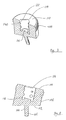
- a dispenser according to the present invention is shown in Fig. 5A, and generally designated as 200.
- the dispenser 200 is of a structure and shape generally similar to that disclosed in EP 0 102 212 A1.
- the dispenser 200 has a body 202 (part of which is shown in Fig. 5A in dotted line) for containing a liquid, e.g. liquid soap.
- a protrusion 204 Extending from and integral with a lower end of the body 202 is a protrusion 204 for insertion into the cavity 114 of the mounting base 100, for engaging the dispenser 200 with the mounting base 100.
- protrusion 204 Provided on the outer surface of the protrusion 204 are two parallel grooves 206a, 206b, for engagement with locking mechanism and engagement mechanism of the mounting base 100, as discussed fully in EP 0 102 212 A1.
- a circular recess 222 receiving the cylindrical extension 116 at the bottom of the cavity 114 of the mounting base 100, so as to support the dispenser 200 more securely.
- a main feature of the protrusion 204 is that most of its transverse cross sections are non-circular. As shown in Figs. 6 and 7, the protrusion 204 has a cut-off region, so that a planar surface 208 is provided on a lateral side of the protrusion 204. In other words, the transverse cross section of the protrusion 204 has a shape of a circle with a cut-out region on its side, as shown more clearly in Fig. 5B.
- the protrusion 204 is sized and shaped to fit within the cavity 114 of the mounting base 100, with the planar lateral side surface 208 of the protrusion 204 matching a planar side surface 140 in the cavity 114 of mounting base 100.
- the protrusion 204 can be fitted stably within the mounting base 100, which complements the cut-out region by providing a compensating region.
- Such a design provides an arrangement to ensure better engagement between the dispenser 200 and the mounting base 100, so that the dispenser 200 is stable during operation of its pump and spout assembly.
- protrusion 204 is shown here as being of a cylindrical shape having a cut-out portion, other shapes may be adopted. It is envisaged that a protrusion in the shape of an oval or triangular prism may be used. The similarity of these non-circular prism protrusion is that at least a transverse cross section thereof is always non-circular. The use of protrusion having such a construction prevents unintended rotation of its protrusion 204, and thus the whole dispenser 100, relative to the mounting base 100.
- Such an arrangement also ensures that the dispenser 200 can only be fitted with the mounting base 100 in one particular orientation, i.e. with the planar lateral side surface 208 of the protrusion 204 matching the planar surface 140 in the cavity 114 of mounting base 100. It is of course possible to form the protrusion 204 of two planar lateral side surfaces, and to form the cavity 114 of the mounting base 100 with at least a complementarily shaped entrance, i.e. in the shape of a circle truncated by two straight lines, so that the dispenser 200 may be engaged with the mounting base 100 in two ways, and two ways only.
- the protrusion may also have a non-cylindrical shape such as the shape of an inverted pyramid, which can achieve the same function of preventing rotation of the liquid dispenser relative to the mounting base. Such will ensure that trade marks and/or logos printed on the body of the liquid dispenser will be viewed by the user.
Landscapes
- Engineering & Computer Science (AREA)
- Mechanical Engineering (AREA)
- Health & Medical Sciences (AREA)
- Public Health (AREA)
- Closures For Containers (AREA)
- Containers And Packaging Bodies Having A Special Means To Remove Contents (AREA)
Applications Claiming Priority (2)
| Application Number | Priority Date | Filing Date | Title |
|---|---|---|---|
| US99208801A | 2001-11-14 | 2001-11-14 | |
| US992088 | 2001-11-14 |
Publications (1)
| Publication Number | Publication Date |
|---|---|
| EP1312294A1 true EP1312294A1 (de) | 2003-05-21 |
Family
ID=25537901
Family Applications (1)
| Application Number | Title | Priority Date | Filing Date |
|---|---|---|---|
| EP02250779A Withdrawn EP1312294A1 (de) | 2001-11-14 | 2002-02-05 | Ein Behälter |
Country Status (1)
| Country | Link |
|---|---|
| EP (1) | EP1312294A1 (de) |
Cited By (2)
| Publication number | Priority date | Publication date | Assignee | Title |
|---|---|---|---|---|
| WO2004004529A1 (en) * | 2002-07-03 | 2004-01-15 | Celeste Industries Corporation | Dispensing system |
| USD500247S1 (en) | 2003-07-03 | 2004-12-28 | Celeste Industries Corporation | Container |
Citations (6)
| Publication number | Priority date | Publication date | Assignee | Title |
|---|---|---|---|---|
| EP0102212A2 (de) | 1982-08-20 | 1984-03-07 | Castrol Limited | Hydraulikflüssigkeiten auf Wasserbasis |
| EP0306114A1 (de) | 1987-09-04 | 1989-03-08 | Shell Internationale Researchmaatschappij B.V. | Herstellungsverfahren von Methanol und Katalysatorzusammensetzung für dieses Verfahren |
| EP0427514A1 (de) * | 1989-11-06 | 1991-05-15 | James River Corporation Of Virginia | Behälter zur Abgabe von Flüssigkeit und Halterungssystem |
| US5148948A (en) * | 1991-07-05 | 1992-09-22 | Celeste Industries Corporation | Liquid soap dispenser with mounting base |
| EP0997384A1 (de) * | 1998-10-28 | 2000-05-03 | Kado Industrial Company Limited | Haltevorrichtung |
| EP1103212A1 (de) * | 1999-11-25 | 2001-05-30 | Kado Industrial Company Limited | Behälter |
-
2002
- 2002-02-05 EP EP02250779A patent/EP1312294A1/de not_active Withdrawn
Patent Citations (6)
| Publication number | Priority date | Publication date | Assignee | Title |
|---|---|---|---|---|
| EP0102212A2 (de) | 1982-08-20 | 1984-03-07 | Castrol Limited | Hydraulikflüssigkeiten auf Wasserbasis |
| EP0306114A1 (de) | 1987-09-04 | 1989-03-08 | Shell Internationale Researchmaatschappij B.V. | Herstellungsverfahren von Methanol und Katalysatorzusammensetzung für dieses Verfahren |
| EP0427514A1 (de) * | 1989-11-06 | 1991-05-15 | James River Corporation Of Virginia | Behälter zur Abgabe von Flüssigkeit und Halterungssystem |
| US5148948A (en) * | 1991-07-05 | 1992-09-22 | Celeste Industries Corporation | Liquid soap dispenser with mounting base |
| EP0997384A1 (de) * | 1998-10-28 | 2000-05-03 | Kado Industrial Company Limited | Haltevorrichtung |
| EP1103212A1 (de) * | 1999-11-25 | 2001-05-30 | Kado Industrial Company Limited | Behälter |
Cited By (2)
| Publication number | Priority date | Publication date | Assignee | Title |
|---|---|---|---|---|
| WO2004004529A1 (en) * | 2002-07-03 | 2004-01-15 | Celeste Industries Corporation | Dispensing system |
| USD500247S1 (en) | 2003-07-03 | 2004-12-28 | Celeste Industries Corporation | Container |
Similar Documents
| Publication | Publication Date | Title |
|---|---|---|
| EP1264540A2 (de) | Ineinanderstapelbare Nahrungsmittelausgabevorrichtungen für Haustiere | |
| USD471108S1 (en) | Bottle and cap combination | |
| CA1235260A (en) | Broom shroud | |
| USD468639S1 (en) | Liquid dispensing closure | |
| US5725527A (en) | Anchoring member | |
| US20050092771A1 (en) | Universal collar key | |
| US20230346171A1 (en) | Lockable receptacle holder | |
| AU3810900A (en) | Precision dispenser for liquids | |
| CN110022740A (zh) | 瓶保持器 | |
| EP0972499A3 (de) | Einweg-Monomerspender und Ampullenbrecher | |
| EP0997384A1 (de) | Haltevorrichtung | |
| WO2004099006A3 (en) | Condiment dispensing container and carousel | |
| USD407273S (en) | Liquid flask with easy pouring spout | |
| EP1312294A1 (de) | Ein Behälter | |
| USD427021S (en) | Liquid decanter with handle and spout | |
| EP1296877B1 (de) | Ausgiesser für flüssigkeiten | |
| HK1056986A (en) | A container | |
| EP1103212A1 (de) | Behälter | |
| EP1326570B1 (de) | Augenspülvorrichtung | |
| KR200405326Y1 (ko) | 리필 화장품 용기 | |
| AU2001296137A1 (en) | An eye rinsing device | |
| JP5193763B2 (ja) | キャップ付き容器 | |
| US20070080086A1 (en) | Tool packaging | |
| JP3259875B2 (ja) | 容 器 | |
| US20030080127A1 (en) | Removable tub |
Legal Events
| Date | Code | Title | Description |
|---|---|---|---|
| PUAI | Public reference made under article 153(3) epc to a published international application that has entered the european phase |
Free format text: ORIGINAL CODE: 0009012 |
|
| AK | Designated contracting states |
Designated state(s): AT BE CH CY DE DK ES FI FR GB GR IE IT LI LU MC NL PT SE TR |
|
| AX | Request for extension of the european patent |
Extension state: AL LT LV MK RO SI |
|
| 17P | Request for examination filed |
Effective date: 20030703 |
|
| AKX | Designation fees paid |
Designated state(s): AT BE CH CY DE DK ES FI FR GB GR IE IT LI LU MC NL PT SE TR |
|
| STAA | Information on the status of an ep patent application or granted ep patent |
Free format text: STATUS: THE APPLICATION HAS BEEN WITHDRAWN |
|
| 18W | Application withdrawn |
Effective date: 20040722 |
|
| REG | Reference to a national code |
Ref country code: HK Ref legal event code: WD Ref document number: 1056986 Country of ref document: HK |