EP1312831A2 - Mécanisme d'écrou et de vis à billes et procédé pour le fabriquer - Google Patents
Mécanisme d'écrou et de vis à billes et procédé pour le fabriquer Download PDFInfo
- Publication number
- EP1312831A2 EP1312831A2 EP02079376A EP02079376A EP1312831A2 EP 1312831 A2 EP1312831 A2 EP 1312831A2 EP 02079376 A EP02079376 A EP 02079376A EP 02079376 A EP02079376 A EP 02079376A EP 1312831 A2 EP1312831 A2 EP 1312831A2
- Authority
- EP
- European Patent Office
- Prior art keywords
- ball
- nut
- crossover
- ledge
- slot
- Prior art date
- Legal status (The legal status is an assumption and is not a legal conclusion. Google has not performed a legal analysis and makes no representation as to the accuracy of the status listed.)
- Granted
Links
Images


Classifications
-
- F—MECHANICAL ENGINEERING; LIGHTING; HEATING; WEAPONS; BLASTING
- F16—ENGINEERING ELEMENTS AND UNITS; GENERAL MEASURES FOR PRODUCING AND MAINTAINING EFFECTIVE FUNCTIONING OF MACHINES OR INSTALLATIONS; THERMAL INSULATION IN GENERAL
- F16H—GEARING
- F16H25/00—Gearings comprising primarily only cams, cam-followers and screw-and-nut mechanisms
- F16H25/18—Gearings comprising primarily only cams, cam-followers and screw-and-nut mechanisms for conveying or interconverting oscillating or reciprocating motions
- F16H25/20—Screw mechanisms
- F16H25/22—Screw mechanisms with balls, rollers, or similar members between the co-operating parts; Elements essential to the use of such members
- F16H25/2204—Screw mechanisms with balls, rollers, or similar members between the co-operating parts; Elements essential to the use of such members with balls
- F16H25/2214—Screw mechanisms with balls, rollers, or similar members between the co-operating parts; Elements essential to the use of such members with balls with elements for guiding the circulating balls
- F16H25/2223—Cross over deflectors between adjacent thread turns, e.g. S-form deflectors connecting neighbouring threads
-
- F—MECHANICAL ENGINEERING; LIGHTING; HEATING; WEAPONS; BLASTING
- F16—ENGINEERING ELEMENTS AND UNITS; GENERAL MEASURES FOR PRODUCING AND MAINTAINING EFFECTIVE FUNCTIONING OF MACHINES OR INSTALLATIONS; THERMAL INSULATION IN GENERAL
- F16H—GEARING
- F16H25/00—Gearings comprising primarily only cams, cam-followers and screw-and-nut mechanisms
- F16H25/18—Gearings comprising primarily only cams, cam-followers and screw-and-nut mechanisms for conveying or interconverting oscillating or reciprocating motions
- F16H25/20—Screw mechanisms
- F16H25/24—Elements essential to such mechanisms, e.g. screws, nuts
- F16H2025/2481—Special features for facilitating the manufacturing of spindles, nuts, or sleeves of screw devices
-
- Y—GENERAL TAGGING OF NEW TECHNOLOGICAL DEVELOPMENTS; GENERAL TAGGING OF CROSS-SECTIONAL TECHNOLOGIES SPANNING OVER SEVERAL SECTIONS OF THE IPC; TECHNICAL SUBJECTS COVERED BY FORMER USPC CROSS-REFERENCE ART COLLECTIONS [XRACs] AND DIGESTS
- Y10—TECHNICAL SUBJECTS COVERED BY FORMER USPC
- Y10T—TECHNICAL SUBJECTS COVERED BY FORMER US CLASSIFICATION
- Y10T74/00—Machine element or mechanism
- Y10T74/19—Gearing
- Y10T74/19642—Directly cooperating gears
- Y10T74/19698—Spiral
- Y10T74/19702—Screw and nut
- Y10T74/19744—Rolling element engaging thread
- Y10T74/19749—Recirculating rolling elements
- Y10T74/19753—Plural independent recirculating element paths
-
- Y—GENERAL TAGGING OF NEW TECHNOLOGICAL DEVELOPMENTS; GENERAL TAGGING OF CROSS-SECTIONAL TECHNOLOGIES SPANNING OVER SEVERAL SECTIONS OF THE IPC; TECHNICAL SUBJECTS COVERED BY FORMER USPC CROSS-REFERENCE ART COLLECTIONS [XRACs] AND DIGESTS
- Y10—TECHNICAL SUBJECTS COVERED BY FORMER USPC
- Y10T—TECHNICAL SUBJECTS COVERED BY FORMER US CLASSIFICATION
- Y10T74/00—Machine element or mechanism
- Y10T74/19—Gearing
- Y10T74/19642—Directly cooperating gears
- Y10T74/19698—Spiral
- Y10T74/19702—Screw and nut
- Y10T74/19744—Rolling element engaging thread
- Y10T74/19749—Recirculating rolling elements
- Y10T74/19767—Return path geometry
- Y10T74/19772—Rolling element deflector
Definitions
- the present invention relates generally to ball screws and ball nuts, and more particularly to a ball-nut assembly having a crossover member and to a method for making a ball-nut assembly having a crossover member.
- Conventional automotive braking systems include those which use a ball-screw-and-ball-nut assembly, wherein the brake booster serves as a housing, wherein the ball screw is turned by a gear driven by an electric brake caliper motor, wherein the ball nut is connected to the brake pad, and wherein rotation of the ball screw axially moves the ball nut.
- an exterior tube extending above the ball nut serves as a crossover for the balls, as is known to the artisan.
- such exterior tubes demand close part tolerances which are expensive and difficult to achieve.
- protruding exterior tubes are not suitable for certain applications such as being housed in a brake caliper housing.
- an internal crossover member is used which is inserted into a radial through slot of the ball nut from inside the ball nut, which abuts a radially-inward-facing ledge of the ball nut surrounding the through slot, and which floats while being captured between the ball screw and the ball nut as is known to the artisan.
- Such internal crossovers are suitable for many applications including being housed in an automotive brake booster.
- Such internal crossovers demand close part tolerances which are expensive and difficult to achieve. If close tolerances are not achieved, the ball screw and ball nut assembly will not work as is known to the artisan.
- a first expression of a first embodiment of the invention is for a ball-nut assembly including a ball nut and a crossover member.
- the ball nut includes a radial through slot and includes an outer surface having a first portion, having a ledge radially recessed from the first portion and at least partially bounding the through slot, and having an undercut wall connecting the ledge and the first portion.
- the crossover member has a flange supported by the ledge and has a crossover-grooved portion positioned in the through slot, wherein the flange has at least one deformed portion contacting the undercut wall of the outer surface of the ball nut.
- a second expression of a first embodiment of the invention is for a ball-screw-and-ball-nut assembly including a ball nut, a crossover member, a ball screw and balls.
- the ball nut includes an inside helical groove, includes a radial through slot, and includes an outer surface having a first portion, having a ledge radially recessed from the first portion and at least partially bounding the through slot, and having an undercut wall connecting the ledge and the first portion.
- the crossover member has a flange supported by the ledge and has a crossover-grooved portion positioned in the through slot, wherein the flange has at least one deformed portion contacting the undercut wall of the outer surface of the ball nut.
- the ball screw includes an outside helical groove and is positioned inside the ball nut. The balls contact the crossover-grooved portion of the crossover member and a portion of the inside and outside helical grooves.
- a first method of the invention is for making a ball- nut assembly and includes steps a) through d).
- Step a) includes obtaining a ball nut including a radial through slot and including an outer surface having a first portion, having a ledge radially recessed from the first portion and at least partially bounding the through slot, and having an undercut wall connecting the ledge and the first portion.
- Step b) includes obtaining a crossover member having a flange and a crossover-grooved portion.
- Step c) includes positioning the crossover member from outside the ball nut to have the flange supported by the ledge and the crossover-grooved portion disposed in the through slot.
- Step d) includes deforming the flange creating a staked portion of the flange which contacts the undercut wall of the outer surface of the ball nut.
- the first method also includes after step a) and before step c) the step on aligning the ball nut on a locating arbor which simulates balls placed around a ball screw and wherein step c) includes aligning the crossover member on the locating arbor and step d) includes using a stake punch.
- first method and the first and second expressions of a first embodiment of the invention Several benefits and advantages are derived from one or more of the first method and the first and second expressions of a first embodiment of the invention.
- the example which includes the stake punch deforms and stakes the crossover member to the undercut wall of the ball nut to maintain the crossover member in proper aligned attachment to the ball nut for smooth operation of a ball-screw-and-ball-nut assembly.
- Figures 1 - 7 illustrate a first embodiment of the present invention.
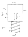
- a first expression of the first embodiment shown in Figures 1-7 is for a ball-nut assembly 10 including a ball nut 12 and a crossover member 14.
- the ball nut 12 includes a radial through slot 16 and includes an outer surface 18.
- the outer surface 18 has a first portion 20, has a ledge 22 radially recessed from the first portion 20 and at least partially bounding the through slot 16, and has an undercut wall 24 connecting the ledge 22 and the first portion 20.
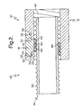
- undercut wall 24 is meant that the undercut wall 24 tilts inward toward the through slot 16 as one moves along the undercut wall 24 from the ledge 22 to the first portion 20 as best seen in Figure 3.
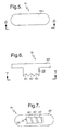
- the crossover member 14 has a flange 26 supported by the ledge 22 and has a crossover-grooved portion 28 disposed in the through slot 16, wherein the flange 26 has at least one deformed portion 30 and 32 contacting the undercut wall 24 of the outer surface 18 of the ball nut 12.
- the contact of the at-least-one deformed portion 30 and 32 with the undercut wall 24 is a staked contact.
- the ledge 22 has an annular shape, surrounds the through slot 16, and annularly supports the flange 26.
- the undercut wall 24 has axially-opposing first and second end portions 34 and 36, and the at-least-one deformed portion 30 and 32 includes first and second deformed portions 30 and 32 respectively contacting a corresponding one of the first and second end portions 34 and 36 of the undercut wall 24.
- the first portion 20 has a cylindrical shape.
- the crossover member 14 has a flat outward facing surface 38 disposed below the first portion 20 of the outer surface 18 of the ball nut 12 which allows the use of an inwardly-protruding pin (not shown) from a surrounding housing (such as an electric brake caliper housing, not shown) to sideways engage the undercut wall 24 (above the crossover member 14) preventing rotation of the ball nut 12 when such rotation is not desired.
- the ball nut 12 is a vehicle-brake-pad-driving ball nut.
- the ball nut 12 is essentially non-ductile, and the crossover member 14 has an elongation ductility of at least four percent.
- the crossover member 14 consists essentially of aluminum, and the ball nut 12 consists essentially of steel.
- the crossover member 14 is a net shape component meaning that it is a molded (such as, but not limited to, using powdered metallurgy techniques), die-cast, or stamped component.
- the tolerances for making the crossover member 14 are substantially twenty thousandths of an inch.
- the undercut wall 24 makes an angle of substantially five to ten degrees (and in one variation substantially seven degrees) from vertical.
- the crossover-grooved portion 28 of the crossover member 14 has three crossover grooves 40.
- a second expression of the first embodiment shown in Figures 1-7 is for a ball-screw-and-ball-nut assembly 42 including a ball nut 12, a crossover member 14, a ball screw 44, and a plurality of balls 46.
- the ball nut 12 includes an inside helical groove 48, includes a radial through slot 16, and includes an outer surface 18.
- the outer surface 18 has a first portion 20, has a ledge 22 radially recessed from the first portion 20 and at least partially bounding the through slot 16, and has an undercut wall 24 connecting the ledge 22 and the first portion 20.
- the crossover member 14 has a flange 26 supported by the ledge 22 and has a crossover-grooved portion 28 disposed in the through slot 16, wherein the flange 26 has at least one deformed portion 30 and 32 contacting the undercut wall 24 of the outer surface 18 of the ball nut 12.
- the ball screw 44 includes an outside helical groove 50 and is disposed inside the ball nut 12.
- the balls 46 contact the crossover-grooved portion 28 of the crossover member 14 and a portion of the inside and outside helical grooves 48 and 50. It is noted that the balls 46 are always axially bounded by the crossover-grooved portion 28 of the crossover member 14, as is understood by the artisan.
- the ball screw 44 is an electric-motor-driven ball screw
- the ball nut 12 is a vehicle-brake-pad-driving ball nut.
- the entire previous multi-paragraph discussion of the first expression of the ball-nut assembly 10 is equally applicable to the second expression of the ball-screw-and-ball-nut assembly 42.
- a first method of the invention is for making a ball-nut assembly 10 and is shown in Figure 8.
- the first method includes steps a) through d).
- Step a) is labeled in block 52 of Figure 8 as "Obtain A Ball Nut”.
- Step a) includes obtaining a ball nut 12 including a radial through slot 16 and including an outer surface 18 having a first portion 20, having a ledge 22 radially recessed from the first portion 20 and at least partially bounding the through slot 16, and having an undercut wall 24 connecting the ledge 22 and the first portion 20.
- Step b) is labeled in block 54 of Figure 8 as "Obtain A Crossover Member”.
- Step b) includes obtaining a crossover member 14 having a flange 26 and a crossover-grooved portion 28.
- Step c) is labeled in block 56 of Figure 8 as "Dispose Crossover Member In Slot Of Ball Nut”.
- Step c) includes disposing the crossover member 14 from outside the ball nut 12 to have the flange 26 supported by the ledge 22 and the crossover-grooved portion 28 disposed in the through slot 16.
- Step d) is labeled in block 58 of Figure 8 as "Deform Flange Of Crossover Member”.
- Step d) includes deforming the flange 26 creating a staked portion (e.g., the at-least-one deformed portion 30 and 32) of the flange 26 which contacts the undercut wall 24 of the outer surface 18 of the ball nut 12. It is noted that, in this method, the contact of the at-least-one deformed portion 30 and 32 with the undercut wall 24 is a staked contact.
- the first method also includes after step a) and before step c) the step of aligning the ball nut 12 on a locating arbor 60 (seen in Figure 9) which simulates balls placed around a ball screw.
- the locating arbor 60 has locating wires 62 soldered into the outside helical groove of a ball-screw-shaped portion of the locating arbor 60 which simulate balls placed around a ball screw.
- the locating wires 62 define only partial arcs so that the ball nut 12 can be axially positioned over the locating wires 62 (without having to be threaded onto them) and then aligned by having the inside helical groove 48 of the ball nut 12 engage the locating wires 62.
- step c) includes aligning the crossover member 14 on the locating arbor 60.
- alignment of the crossover member 14 is accomplished by engaging the crossover grooves 40 with the locating wires 62.
- the first method also includes between steps c) and d) the step of checking the radial position of the crossover member 14 with a position indicator 64.
- the first method also includes between steps c) and d) the step of clamping the crossover member 14 against the locating arbor 60 such as with a spring-loaded clamp 66.
- step d) includes using a stake punch (two stake punches 68 are shown in Figure 9).
- the locating arbor 60 (including the locating wires 62), the position indicator 64, the clamp 66, and the stake punch 68 are components of apparatus 70 for making the ball-nut assembly 10.
- first method and the first and second expressions of a first embodiment of the invention Several benefits and advantages are derived from one or more of the first method and the first and second expressions of a first embodiment of the invention.
- the example which includes the stake punch deforms and stakes the crossover member to the undercut wall of the ball nut to maintain the crossover member in proper aligned attachment to the ball nut for smooth operation of a ball-screw-and-ball-nut assembly.
Landscapes
- Engineering & Computer Science (AREA)
- General Engineering & Computer Science (AREA)
- Mechanical Engineering (AREA)
- Transmission Devices (AREA)
- Forging (AREA)
Applications Claiming Priority (2)
| Application Number | Priority Date | Filing Date | Title |
|---|---|---|---|
| US10/001,715 US6813970B2 (en) | 2001-11-15 | 2001-11-15 | Ball-nut assembly and method for making |
| US1715 | 2001-11-15 |
Publications (3)
| Publication Number | Publication Date |
|---|---|
| EP1312831A2 true EP1312831A2 (fr) | 2003-05-21 |
| EP1312831A3 EP1312831A3 (fr) | 2006-04-19 |
| EP1312831B1 EP1312831B1 (fr) | 2009-08-05 |
Family
ID=21697458
Family Applications (1)
| Application Number | Title | Priority Date | Filing Date |
|---|---|---|---|
| EP02079376A Expired - Lifetime EP1312831B1 (fr) | 2001-11-15 | 2002-10-21 | Mécanisme d'écrou et de vis à billes et procédé pour le fabriquer |
Country Status (3)
| Country | Link |
|---|---|
| US (2) | US6813970B2 (fr) |
| EP (1) | EP1312831B1 (fr) |
| DE (1) | DE60233193D1 (fr) |
Cited By (1)
| Publication number | Priority date | Publication date | Assignee | Title |
|---|---|---|---|---|
| EP2492533A1 (fr) * | 2011-01-18 | 2012-08-29 | Goodrich Corporation | Ensemble formant vis sphérique |
Families Citing this family (10)
| Publication number | Priority date | Publication date | Assignee | Title |
|---|---|---|---|---|
| US6813970B2 (en) * | 2001-11-15 | 2004-11-09 | Delphi Technologies, Inc. | Ball-nut assembly and method for making |
| US7267616B2 (en) * | 2004-08-27 | 2007-09-11 | Delphi Technologies, Inc. | Method for making a ball-nut and method for making a ball-screw |
| US7677126B2 (en) * | 2005-03-22 | 2010-03-16 | Gm Global Technology Operations, Inc. | Ball screw mechanism |
| US20070029142A1 (en) * | 2005-08-03 | 2007-02-08 | Drennen David B | Brake system including ball screw and nut assembly |
| US7487692B2 (en) * | 2006-04-13 | 2009-02-10 | Hiwin Technologies Corp. | Guiding device for ball nut |
| JP5255503B2 (ja) * | 2009-03-31 | 2013-08-07 | Thk株式会社 | 転動体ねじ装置 |
| EP3096041B1 (fr) * | 2011-04-19 | 2018-12-12 | Aktiebolaget SKF | Ensemble de vis sphérique doté d'éléments de déviation d'un seul tenant |
| JP6805752B2 (ja) * | 2016-11-25 | 2020-12-23 | 株式会社ジェイテクト | ボールねじ装置、及びボールねじ装置を備えたステアリング装置 |
| US10106139B2 (en) | 2017-02-02 | 2018-10-23 | Goodrich Corporation | Brake systems and methods |
| CN109676356A (zh) * | 2018-12-27 | 2019-04-26 | 天津航天长征技术装备有限公司 | 一种便捷式滚珠丝杠组装装置 |
Family Cites Families (22)
| Publication number | Priority date | Publication date | Assignee | Title |
|---|---|---|---|---|
| US2121464A (en) * | 1933-07-31 | 1938-06-21 | Zagorski Johann | Annular valve seat |
| US2628869A (en) * | 1950-01-20 | 1953-02-17 | Globe Union Inc | Roller-skate wheel |
| US2905124A (en) * | 1955-09-26 | 1959-09-22 | Continental Can Co | Method of attaching a bail ear |
| US3205001A (en) * | 1964-06-09 | 1965-09-07 | Strick Trailers | Continuous, self-locking means and method of attaching roof sheet to sides of vehicle body |
| US3290077A (en) * | 1964-07-15 | 1966-12-06 | Aluminum Co Of America | Joining and jointed structures |
| FR1478442A (fr) * | 1966-02-16 | 1967-04-28 | Messier Fa | Dispositif de commande mécanique de frein à disque, à rattrapage d'usure automatique |
| US3850046A (en) * | 1972-04-17 | 1974-11-26 | Skf Ind Trading & Dev | Ball nut screw |
| US3913421A (en) * | 1974-06-05 | 1975-10-21 | Du Pont | Method for installing a capillary insert in a passage through a spinneret |
| DE2914756C2 (de) * | 1979-04-11 | 1982-03-25 | Deutsche Star Kugelhalter Gmbh, 8720 Schweinfurt | Kugelschraubtrieb |
| GB2187259A (en) * | 1986-02-21 | 1987-09-03 | Johnson Precision Ltd | Nut for a recirculating ballscrew arrangement |
| IT1219011B (it) * | 1988-02-11 | 1990-04-24 | Roltra Spa | Accoppiamento vite madrevite a circolazione di sfere |
| US5375323A (en) * | 1991-10-30 | 1994-12-27 | Nsk Ltd. | Method for securing shaft of cam follower device for valve action mechanism |
| JP2760455B2 (ja) * | 1991-11-20 | 1998-05-28 | 本田技研工業株式会社 | ナットスクリュのリターンピース固着方法及びボールスクリュの組立て方法。 |
| DE4316614A1 (de) * | 1992-05-18 | 1993-11-25 | Trw Vehicle Safety Systems | Aufblasvorrichtung für eine Fahrzeugluftsackanordnung sowie Verfahren zur Herstellung derselben |
| FR2703122B1 (fr) * | 1993-03-24 | 1995-07-13 | Transrol | Dispositif de recirculation des billes sur des systemes vis-ecrous a billes. |
| JPH07190161A (ja) * | 1993-12-27 | 1995-07-28 | Nippon Seiko Kk | 内部循環式ボールねじ装置 |
| US6112610A (en) * | 1997-08-05 | 2000-09-05 | Thomson Saginaw Ball Screw Company, Llc | Externally insertable self-retaining crossover for ball nut and screw assemblies |
| US5937700A (en) * | 1998-05-12 | 1999-08-17 | Thomson Saginaw Ball Screw Company, L.L.C. | Externally installable ball return crossover systems for ball nut and screw assemblies and methods of constructing and installing them |
| JP3844922B2 (ja) * | 1999-11-04 | 2006-11-15 | Ntn株式会社 | ボールねじおよびそれを具備する電動パワーステアリング装置 |
| JP3844943B2 (ja) * | 2000-04-03 | 2006-11-15 | Ntn株式会社 | ボールねじおよびそれを具備する電動パワーステアリング装置 |
| PL366732A1 (en) * | 2001-07-19 | 2005-02-07 | Nsk Ltd. | Method for working nut screw for ball screw |
| US6813970B2 (en) * | 2001-11-15 | 2004-11-09 | Delphi Technologies, Inc. | Ball-nut assembly and method for making |
-
2001
- 2001-11-15 US US10/001,715 patent/US6813970B2/en not_active Expired - Lifetime
-
2002
- 2002-10-21 DE DE60233193T patent/DE60233193D1/de not_active Expired - Lifetime
- 2002-10-21 EP EP02079376A patent/EP1312831B1/fr not_active Expired - Lifetime
-
2004
- 2004-11-05 US US10/982,126 patent/US20050061099A1/en not_active Abandoned
Cited By (3)
| Publication number | Priority date | Publication date | Assignee | Title |
|---|---|---|---|---|
| EP2492533A1 (fr) * | 2011-01-18 | 2012-08-29 | Goodrich Corporation | Ensemble formant vis sphérique |
| US8402852B2 (en) | 2011-01-18 | 2013-03-26 | Goodrich Corporation | Ballscrew assembly |
| US9611923B2 (en) | 2011-01-18 | 2017-04-04 | Goodrich Corporation | Ballscrew assembly |
Also Published As
| Publication number | Publication date |
|---|---|
| US20030089188A1 (en) | 2003-05-15 |
| US20050061099A1 (en) | 2005-03-24 |
| EP1312831B1 (fr) | 2009-08-05 |
| EP1312831A3 (fr) | 2006-04-19 |
| DE60233193D1 (de) | 2009-09-17 |
| US6813970B2 (en) | 2004-11-09 |
Similar Documents
| Publication | Publication Date | Title |
|---|---|---|
| EP1312831B1 (fr) | Mécanisme d'écrou et de vis à billes et procédé pour le fabriquer | |
| US6053653A (en) | Fastening method, fastening system and bolt used therefor | |
| JP7439648B2 (ja) | ボールねじ装置 | |
| US20050025605A1 (en) | Locator stud and method of assembly | |
| EP2168785B1 (fr) | Appareil de roulement | |
| DE102023204926A1 (de) | Anordnung zur Erfassung einer Lagerkraft eines Tretlagers eines mit Muskelkraft und/oder Motorkraft betreibbaren Fahrzeugs | |
| US20070113618A1 (en) | Knock sensor | |
| US5913633A (en) | Arrangement for joining outer ring and shaft of homokinetic joint | |
| CN216774542U (zh) | 马达单元 | |
| JP4319801B2 (ja) | 金属板へのねじ装置の固定方法 | |
| JP2007518617A (ja) | 車輪保持体にある車輪軸受モジュール | |
| JPS62104633A (ja) | 板状部材の固定方法 | |
| JP3190264B2 (ja) | Tナットの製造方法 | |
| WO2007066525A1 (fr) | Dispositif de roulement pour roue et procédé de fabrication de celui-ci | |
| CN213279405U (zh) | 电动致动器 | |
| JP5051075B2 (ja) | ボールねじ機構 | |
| JP2005147346A (ja) | 金具固定構造と金具固定方法 | |
| US6851759B2 (en) | Retaining a brake rotor in an vehicle corner apparatus | |
| JP2005076741A (ja) | 配管継手構造およびその製造方法 | |
| JP3054847U (ja) | クリンチナット | |
| US20040037620A1 (en) | Ball joint | |
| JP3100942B2 (ja) | 固着装置の回止め及びその成形方法 | |
| JP3073756U (ja) | フランジ付軸受 | |
| CN121624812A (zh) | 用于机电制动器的形状配合连接的多件式壳体及制造方法 | |
| CN120728955A (zh) | 驱动装置以及装配方法 |
Legal Events
| Date | Code | Title | Description |
|---|---|---|---|
| PUAI | Public reference made under article 153(3) epc to a published international application that has entered the european phase |
Free format text: ORIGINAL CODE: 0009012 |
|
| AK | Designated contracting states |
Designated state(s): AT BE BG CH CY CZ DE DK EE ES FI FR GB GR IE IT LI LU MC NL PT SE SK TR |
|
| AX | Request for extension of the european patent |
Extension state: AL LT LV MK RO SI |
|
| PUAL | Search report despatched |
Free format text: ORIGINAL CODE: 0009013 |
|
| AK | Designated contracting states |
Kind code of ref document: A3 Designated state(s): AT BE BG CH CY CZ DE DK EE ES FI FR GB GR IE IT LI LU MC NL PT SE SK TR |
|
| AX | Request for extension of the european patent |
Extension state: AL LT LV MK RO SI |
|
| 17P | Request for examination filed |
Effective date: 20061019 |
|
| AKX | Designation fees paid |
Designated state(s): DE FR GB IT |
|
| 17Q | First examination report despatched |
Effective date: 20070807 |
|
| GRAP | Despatch of communication of intention to grant a patent |
Free format text: ORIGINAL CODE: EPIDOSNIGR1 |
|
| GRAS | Grant fee paid |
Free format text: ORIGINAL CODE: EPIDOSNIGR3 |
|
| GRAA | (expected) grant |
Free format text: ORIGINAL CODE: 0009210 |
|
| AK | Designated contracting states |
Kind code of ref document: B1 Designated state(s): DE FR GB IT |
|
| REG | Reference to a national code |
Ref country code: GB Ref legal event code: FG4D |
|
| REF | Corresponds to: |
Ref document number: 60233193 Country of ref document: DE Date of ref document: 20090917 Kind code of ref document: P |
|
| PGFP | Annual fee paid to national office [announced via postgrant information from national office to epo] |
Ref country code: GB Payment date: 20091021 Year of fee payment: 8 |
|
| PLBE | No opposition filed within time limit |
Free format text: ORIGINAL CODE: 0009261 |
|
| STAA | Information on the status of an ep patent application or granted ep patent |
Free format text: STATUS: NO OPPOSITION FILED WITHIN TIME LIMIT |
|
| 26N | No opposition filed |
Effective date: 20100507 |
|
| PG25 | Lapsed in a contracting state [announced via postgrant information from national office to epo] |
Ref country code: IT Free format text: LAPSE BECAUSE OF FAILURE TO SUBMIT A TRANSLATION OF THE DESCRIPTION OR TO PAY THE FEE WITHIN THE PRESCRIBED TIME-LIMIT Effective date: 20090805 |
|
| GBPC | Gb: european patent ceased through non-payment of renewal fee |
Effective date: 20101021 |
|
| PG25 | Lapsed in a contracting state [announced via postgrant information from national office to epo] |
Ref country code: GB Free format text: LAPSE BECAUSE OF NON-PAYMENT OF DUE FEES Effective date: 20101021 |
|
| PGFP | Annual fee paid to national office [announced via postgrant information from national office to epo] |
Ref country code: FR Payment date: 20131009 Year of fee payment: 12 |
|
| REG | Reference to a national code |
Ref country code: FR Ref legal event code: ST Effective date: 20150630 |
|
| PG25 | Lapsed in a contracting state [announced via postgrant information from national office to epo] |
Ref country code: FR Free format text: LAPSE BECAUSE OF NON-PAYMENT OF DUE FEES Effective date: 20141031 |
|
| PGFP | Annual fee paid to national office [announced via postgrant information from national office to epo] |
Ref country code: DE Payment date: 20171018 Year of fee payment: 16 |
|
| REG | Reference to a national code |
Ref country code: DE Ref legal event code: R119 Ref document number: 60233193 Country of ref document: DE |
|
| PG25 | Lapsed in a contracting state [announced via postgrant information from national office to epo] |
Ref country code: DE Free format text: LAPSE BECAUSE OF NON-PAYMENT OF DUE FEES Effective date: 20190501 |