EP1312876B1 - Kälteaggregat mit umkehrbarem Kreislauf - Google Patents
Kälteaggregat mit umkehrbarem Kreislauf Download PDFInfo
- Publication number
- EP1312876B1 EP1312876B1 EP02025747A EP02025747A EP1312876B1 EP 1312876 B1 EP1312876 B1 EP 1312876B1 EP 02025747 A EP02025747 A EP 02025747A EP 02025747 A EP02025747 A EP 02025747A EP 1312876 B1 EP1312876 B1 EP 1312876B1
- Authority
- EP
- European Patent Office
- Prior art keywords
- refrigerant
- heat exchanger
- joint pipeline
- valve
- pipeline
- Prior art date
- Legal status (The legal status is an assumption and is not a legal conclusion. Google has not performed a legal analysis and makes no representation as to the accuracy of the status listed.)
- Expired - Lifetime
Links
Images

Classifications
-
- F—MECHANICAL ENGINEERING; LIGHTING; HEATING; WEAPONS; BLASTING
- F25—REFRIGERATION OR COOLING; COMBINED HEATING AND REFRIGERATION SYSTEMS; HEAT PUMP SYSTEMS; MANUFACTURE OR STORAGE OF ICE; LIQUEFACTION SOLIDIFICATION OF GASES
- F25B—REFRIGERATION MACHINES, PLANTS OR SYSTEMS; COMBINED HEATING AND REFRIGERATION SYSTEMS; HEAT PUMP SYSTEMS
- F25B13/00—Compression machines, plants or systems, with reversible cycle
-
- F—MECHANICAL ENGINEERING; LIGHTING; HEATING; WEAPONS; BLASTING
- F25—REFRIGERATION OR COOLING; COMBINED HEATING AND REFRIGERATION SYSTEMS; HEAT PUMP SYSTEMS; MANUFACTURE OR STORAGE OF ICE; LIQUEFACTION SOLIDIFICATION OF GASES
- F25B—REFRIGERATION MACHINES, PLANTS OR SYSTEMS; COMBINED HEATING AND REFRIGERATION SYSTEMS; HEAT PUMP SYSTEMS
- F25B2313/00—Compression machines, plants or systems with reversible cycle not otherwise provided for
- F25B2313/025—Compression machines, plants or systems with reversible cycle not otherwise provided for using multiple outdoor units
- F25B2313/0253—Compression machines, plants or systems with reversible cycle not otherwise provided for using multiple outdoor units in parallel arrangements
- F25B2313/02531—Compression machines, plants or systems with reversible cycle not otherwise provided for using multiple outdoor units in parallel arrangements during cooling
-
- F—MECHANICAL ENGINEERING; LIGHTING; HEATING; WEAPONS; BLASTING
- F25—REFRIGERATION OR COOLING; COMBINED HEATING AND REFRIGERATION SYSTEMS; HEAT PUMP SYSTEMS; MANUFACTURE OR STORAGE OF ICE; LIQUEFACTION SOLIDIFICATION OF GASES
- F25B—REFRIGERATION MACHINES, PLANTS OR SYSTEMS; COMBINED HEATING AND REFRIGERATION SYSTEMS; HEAT PUMP SYSTEMS
- F25B2313/00—Compression machines, plants or systems with reversible cycle not otherwise provided for
- F25B2313/025—Compression machines, plants or systems with reversible cycle not otherwise provided for using multiple outdoor units
- F25B2313/0253—Compression machines, plants or systems with reversible cycle not otherwise provided for using multiple outdoor units in parallel arrangements
- F25B2313/02533—Compression machines, plants or systems with reversible cycle not otherwise provided for using multiple outdoor units in parallel arrangements during heating
-
- F—MECHANICAL ENGINEERING; LIGHTING; HEATING; WEAPONS; BLASTING
- F25—REFRIGERATION OR COOLING; COMBINED HEATING AND REFRIGERATION SYSTEMS; HEAT PUMP SYSTEMS; MANUFACTURE OR STORAGE OF ICE; LIQUEFACTION SOLIDIFICATION OF GASES
- F25B—REFRIGERATION MACHINES, PLANTS OR SYSTEMS; COMBINED HEATING AND REFRIGERATION SYSTEMS; HEAT PUMP SYSTEMS
- F25B2400/00—Component parts or details not otherwise provided for in this subclass
- F25B2400/04—Refrigeration circuit bypassing means
- F25B2400/0415—Refrigeration circuit bypassing means for receivers
-
- F—MECHANICAL ENGINEERING; LIGHTING; HEATING; WEAPONS; BLASTING
- F25—REFRIGERATION OR COOLING; COMBINED HEATING AND REFRIGERATION SYSTEMS; HEAT PUMP SYSTEMS; MANUFACTURE OR STORAGE OF ICE; LIQUEFACTION SOLIDIFICATION OF GASES
- F25B—REFRIGERATION MACHINES, PLANTS OR SYSTEMS; COMBINED HEATING AND REFRIGERATION SYSTEMS; HEAT PUMP SYSTEMS
- F25B2400/00—Component parts or details not otherwise provided for in this subclass
- F25B2400/16—Receivers
-
- F—MECHANICAL ENGINEERING; LIGHTING; HEATING; WEAPONS; BLASTING
- F25—REFRIGERATION OR COOLING; COMBINED HEATING AND REFRIGERATION SYSTEMS; HEAT PUMP SYSTEMS; MANUFACTURE OR STORAGE OF ICE; LIQUEFACTION SOLIDIFICATION OF GASES
- F25B—REFRIGERATION MACHINES, PLANTS OR SYSTEMS; COMBINED HEATING AND REFRIGERATION SYSTEMS; HEAT PUMP SYSTEMS
- F25B2400/00—Component parts or details not otherwise provided for in this subclass
- F25B2400/19—Pumping down refrigerant from one part of the cycle to another part of the cycle, e.g. when the cycle is changed from cooling to heating, or before a defrost cycle is started
Definitions
- the field of this invention is reversible cycle cooling unit.
- this invention is used on a reversible cycle cooling unit for centralised air-conditioning systems, to which this text will explicitly refer without loss in generality.
- centralised air-conditioning systems normally comprise of a cooling unit that cools the liquid circulating in the radiators and/or fan-coils that belong to the system, so as they subtract heat from the inside environment in order to lower the air temperature inside the different rooms of the building where they are placed.
- the cooling unit/s work/s according to the heat pump principle and can cool or heat the liquid circulating inside the hydraulic circuit of the air-conditioning system, so as the radiators and/or the fan-coils, selectively and according to the season, subtract or give heat to the ambient without using a boiler.
- said cooling units can change over from one working modality to the other one and, therefore, comprises of two different refrigerant circuits, so as the refrigerant can flow in proper sequence to said two heat exchangers belonging to the unit, so as the unit can selectively work in one of the two possible operation modalities.
- cooling circuits normally used cause a lot of problems: first of all, after the change over from one operation modality to the other, it's particularly difficult to empty the components of the circuit in which the refrigerant does not flow any more, obliging, therefore, the manufacturer to over-charge with refrigerant the cooling unit in order to have always the sufficient quantity of refrigerant flowing into the cooling circuit, so as the cooling unit can properly work in both operating modality.
- the purpose of this invention is therefore to make a reversible cycle cooling unit free from the above mentioned drawbacks.
- a cooling unit with reversible cycle comprising a first heat exchanger in which the refrigerant exchanges heat with the outside environment; a second heat exchanger in which said refrigerant exchanges heat with a generic liquid, a compression device for compressing said refrigerant, and a distributor for distributing said refrigerant and which selectively connects said compression device to said first and said second heat exchangers; said cooling unit also comprising a first joint pipeline which connects said first heat exchanger to said second heat exchanger and, along said first joint pipeline, a first expansion valve in which said refrigerant quickly expands; said cooling unit being characterized in that it also comprises a first check valve and an intercepting valve in sequence along said first joint pipeline prior to said first expansion valve, a drier filter positioned along said first joint pipeline between said first check valve and said intercepting valve, and a by-pass circuit of said first expansion valve; said by-pass circuit comprising a second joint pipeline with a first extremity connected to said first joint pipeline,
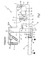
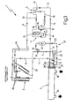
- number 1 shows a whole reversible cycle cooling unit that can be used in building centralized air-conditioning systems.
- These systems usually include a series of radiators and/or fan-coils properly distributed in the building inside of which the air temperature has to be controlled, and, at least, a cooling unit able to heat or cool the heat conveying liquid (normally water) conveyed to said radiators and/or fan-coils, through the hydraulic circuits, in the air-conditioning system itself.
- a cooling unit able to heat or cool the heat conveying liquid (normally water) conveyed to said radiators and/or fan-coils, through the hydraulic circuits, in the air-conditioning system itself.
- the reversible cycle cooling unit 1 works according to the heat pump principle that permits to transfer heat from one environment to another, using a refrigerant in gas state in a closed thermodynamic cycle as, for example, a Carnot cycle.
- a refrigerant in gas state in a closed thermodynamic cycle as, for example, a Carnot cycle.
- the thermodynamic principles used in heat pump units are widely known and they will not be further explained.
- the cooling unit 1 comprises of a first heat exchanger 2, with which the refrigerant exchanges heat with the outside environment; a second heat exchanger 3, with which the refrigerant exchanges heat with the heat conveying liquid that flows into the radiators and/or to the fan-coils of the hydraulic circuit of the air-conditioning system; and a refrigerant compression device 4 for compressing said refrigerant (for example with an adiabatic compression), so that the pressure of the refrigerant outgoing the compression device 4 is higher than the pressure that the refrigerant had in the suction side inlet of the compression device itself.
- the cooling unit 1 also comprises a refrigerant distributor 5, that selectively connects, under control and in the proper way, the delivery 4a and the suction side 4b of the compression device 4 to the heat exchangers 2 and 3.
- distributor 5 selectively connects the delivery 4a and the suction 4b of the compression device 4 to said heat exchangers 2 and 3, so as to enable the cooling unit 1, on choice, to chill the heat conveying liquid circulating in the hydraulic circuit of the air-conditioning system, transferring heat to the outside environment, or to heat the heat conveying liquid circulating in the hydraulic circuit of the air-conditioning system, taking heat from the outside environment.
- the heat exchangers 2 and 3 and the compression device 4 are widely used in this field and so, here, are not described in details.
- the heat exchanger 2 permits the heat exchange between the refrigerant and the outside environment in such a way as to cause the condensation or the evaporation of the refrigerant, depending on the difference in temperature between the refrigerant and the external temperature.
- heat exchanger 2 permits the refrigerant to cool progressively transferring heat to the outside environment, with the possibility to change state from gas to liquid.
- heat exchanger 2 permits the refrigerant, that flows through the exchanger itself, to warm up progressively taking heat from the outside environment, with the possibility to change its state from liquid to gas.
- heat exchanger 2 is provided with two inlets and two outlets for the refrigerant that are properly connected between them in order to have, inside heat exchanger 2, a cooling path, flowing into which the refrigerant with high temperature progressively cools giving heat to the outside environment with the possibility to change state from gas to liquid, and a heating path, flowing into which the refrigerant with low temperature grows progressively hot taking heat from the outside environment with the possibility to change state from liquid to gas.
- heat exchanger 2 is constituted of a forced air heat exchanger for external installation of known kind, that is provided with an inlet 2a for the high temperature refrigerant in gas state, with an outlet 2b for the low temperature refrigerant in liquid state, with an inlet 2c for the low temperature refrigerant in liquid state, and finally with an outlet 2d for the high temperature refrigerant in gas state that is the inlet 2a.
- the inlet 2a and the outlet 2b of the heat exchanger 2 are the limits of the cooling path and are connected the first directly to the distributor 5 by a first joint pipeline 6, and the second directly to heat exchanger 3 by a first joint pipeline 7, comprising of a check valve 8, a drier filter 9 and an intercepting valve 10, connected in series.
- the check valve 8 is orientated in order to permit the downflow of the refrigerant only from heat exchanger 2 to the drier filter 9.
- the intercepting valve 10 selectively does not permit the flowing of the refrigerant along the pipeline 7 from said drier filter 9 to the heat exchanger 3.
- the inlet 2c and the outlet 2d of the heat exchanger 2 are, instead, the limits of the heating path, and are connected the first directly to the heat exchanger 3 by a joint pipeline 11 that joins itself to pipeline 7 between the drier filter 9 and the intercepting valve 10, and the second directly to distributor 5 by pipeline 6.
- heat exchanger 3 permits the refrigerant to exchange heat with the heat conveying liquid that is flowing into the radiators and/or fan-coils, so as to increase or reduce the temperature of the refrigerant, taking away or giving heat to the heat conveying liquid circulating in the air-conditioning system.
- the heat exchanger 3 permits the refrigerant that flows through the heat exchanger to cool progressively giving heat to the heat conveying liquid that in this way warms up.
- heat exchanger 3 permits the refrigerant that flows through the heat exchanger to warm up progressively absorbing heat from the heat conveying liquid that in this way cools.
- Heat exchanger 3 comprises of a primary circuit through which flows the heat conveying liquid circulating into the radiators and/or to the fan-coils of the system, and a secondary circuit through which flows the refrigerant.
- the inlet and the outlet of the primary circuit are connected to the hydraulic circuit of the air-conditioning system, whereas the inlet and the outlet of the secondary circuit, later on indicated with 3c and 3d, are connected one directly to heat exchanger 2 and the other to the distributor 5.
- inlet 3c of heat exchanger 3 is directly connected to pipeline 7, whereas outlet 3d is connected to distributor 5 by the joint pipeline 13.
- the compression device is, as said before, of known kind and consists of a traditional screw or piston (or similar) compressor 14 for compressing gas state refrigerants , and a liquid/gas separating tank 15, positioned upstream of the suction inlet of compressor 14 in order to avoid the refrigerant in liquid state to reach the suction inlet of compressor 14, damaging it irreparably.
- the compression device 4 also comprises of a check valve 16 positioned immediately downstream of the delivery outlet of compressor 14 and orientated in order to permit the refrigerant to flow only in outlet from the compressor 14 itself.
- distributor 5 of unit 1 comprises of a traditional reversing four way valve with electrical control.
- the reversing four way valve 17 in particular, is a slide valve and is provided with four inlets, selectively connectable directly to one another in pairs, and it is made to operate alternatively in two distinct operative configurations enabling two of the four inlets of the valve to be directly and alternatively connected either to one or the other of the remaining two inlets of the valve.
- the reversing four way valve 17 comprises of two primary and two secondary inlets.
- the primary inlets can be connected selectively and alternatively to all of the secondary inlets of the valve, without coming into direct contact with each other.
- the reversing four way valve 17 is provided with four inlets, indicated respectively with 17a,17b,17c,17d, and can take two different operative configurations: in the first, inlet 17a is in direct communication with inlet 17b and inlet 17c is in direct communication with inlet 17d; in the second, inlet 17a is in direct communication with inlet 17d and inlet 17c is in direct communication with inlet 17b.
- inlet 17a of the reversing four way valve 17 is connected with the delivery 4a of the compression device 5 by pipeline 18; inlet 17b is connected directly to pipeline 6; inlet 17c is connected by pipeline 19 directly to the suction side 4b of the compression device 4; finally inlet 17d of the reversing four way valve 17 is directly connected to pipeline 13 that comes from heat exchanger 3.
- inlets 17a and 17c are primary inlets of the reversing four way valve 17, and that inlets 17b and 17d are secondary inlets of the valve.
- the cooling unit 1 finally comprises of at least one expansion valve 20 that permits the quick expansion of the refrigerant, in order to complete the closed thermodynamic cycle in contrast with the compression device 4 that causes, on the contrary, the quick compression of the refrigerant.
- expansion valve 20 permits the quick expansion of the flowing refrigerant, in order to make the pressure of the refrigerant outgoing from expansion valve 20 much lower that the pressure that the refrigerant had in the inlet of the valve itself, and it is obviously positioned along the pipeline that connects the heat exchanger, at which the refrigerant coming out from the compression device cools, to the heat exchanger at which the refrigerant warms up before returning to the compression device 4.
- cooling unit 1 comprises of three expansion valves 20: the first is positioned along pipeline 7 between inlet 3c of the heat exchanger 3 and the intercepting valve 10, whereas the second and the third expansion valves 20 are positioned along pipeline 11 in correspondence of inlet 2c of the heat exchanger 2.
- the cooling unit 1 finally comprises of also a by-pass circuit 21 of the expansion valve 20 positioned along the pipeline 7.
- the by-pass circuit 21 comprises of a joint pipeline 22, that has the first extremity connected in offtake to pipeline 7 between inlet 3c of heat exchanger 3 and expansion valve 20, and the second extremity connected in offtake to pipeline 7 between check valve 8 and drier filter 9; a refrigerant storage tank 23 positioned along the joint pipeline 22; and finally a check valve positioned on pipeline 22 between the storage tank 23 and pipeline 7.
- the check valve 24 is orientated in order to permit the downflow of the refrigerant only from the storage tank 23 to drier filter 9, but not vice-versa.
- cooling unit 1 operates only to cool the heat conveying liquid circulating in heat exchanger 3 and transferring heat to the outside environment by heat exchanger 2.
- the intercepting valve 10 is in opened position, and the reversing four way valve 17 is in the first operative position so that inlet 17a is in direct communication with inlet 17b and inlet 17c is in direct communication with inlet 17d.
- the refrigerant outgoing from compressor 14 flows through check valve 16 and reaches inlet 17a of the reversing four way valve 17 of the distributor 5. Once it has reached inlet 17a, the refrigerant flows through the reversing four way valve 17 and goes out from inlet 17b, then flows along pipeline 6 as far as inlet 2a of the heat exchanger 2, at which it gives heat to the outside environment, cooling itself.
- the refrigerant comes out from the heat exchanger 2 through outlet 2b and, flowing along pipeline 7, flows through, in sequence, the check valve 8, drier filter 9, intercepting valve 10 and finally expansion valve 20, at which it is subjected to a quick expansion before going in inlet 3c of heat exchanger 3.
- the refrigerant takes heat from the heat conveying liquid circulating in the hydraulic circuit of the air-conditioning system, to flow, after, along pipeline 13 to distributor 5 and from here again to compressor 14, upon passage in the liquid/gas separator tank 15.
- the refrigerant leaving heat exchanger 3 flows through pipeline 13 as to reach inlet 17d of reversing four way valve 17, goes out from inlet 17c of the valve itself and from here flows through pipeline 19 as far as the liquid/gas separating tank 15 which communicates directly with the suction of compressor 14.
- outlet 3d of heat exchanger 3 is in direct communication with suction side 4b of the compression device 4, the latter being able to suck by depression not only the refrigerant flowing in pipeline 7, but also all the refrigerant accumulated in the by-pass circuit 21, comprising of pipeline 22 and storage tank 23.
- the emptying of by-pass circuit 21 doesn't cause any obstacle to the normal downflow of the refrigerant from heat exchanger 2 along pipeline 7.
- the electronic control device (not illustrated) that controls the working of the cooling unit 1 closes the intercepting valve 10 and enables the commutation of the reversing four way valve 17 from the first to the second operative position.
- the refrigerant leaving from compressor 14 flows through check valve 16, reaches inlet 17a of the reversing four way valve 17 of the distributor 5, goes out from inlet 17d of the reversing four way valve 17, flows through pipeline 13 and goes in the heat exchanger 3 through the outlet 3d.
- the refrigerant after having given heat to the heat conveying liquid circulating in the heat exchanger 3, goes out from inlet 3c of heat exchanger 3; flows through pipeline 7 and goes into the by-pass circuit 21 before reaching the expansion valve 20 in pipeline 7; flows through pipeline 22 flowing through, in sequence, the storage tank 23 and the check valve 24; finally reaches again pipeline 7 upstream the drier filter 9.
- the intercepting valve 10 in the closed position, obstructs the flow of the refrigerant along pipeline 7 where the expansion valve 20 is positioned.
- the refrigerant goes through drier filter 9 and flows in pipeline 11 to the expansion valve 20 reaching inlet 2c of the heat exchanger 2.
- the refrigerant is subjected to a quick expansion (for example to an adiabatic expansion) with following quick drop of its temperature.
- the refrigerant When flowing in heat exchanger 2, the refrigerant warms up taking heat from the outside environment; the refrigerant goes out from the exchanger 2 through inlet 2d and flows along pipeline 6 as far as the inlet 17b of the reversing four way valve 17.
- the refrigerant After entering in four way valve 17, the refrigerant goes out from inlet 17c of the valve, flows through pipeline 19 as far as the liquid gas separator 15 that communicates directly with the suction side of the compressor 14.
- the new position of the check valve 8, of the drier filter 9, of the intercepting valve 10 and of the expansion valve 20 along the pipeline 7 and the by-pass circuit 21 made in this way, enable the quick and complete emptying of the components of the circuit that are not used when in summer season working mode, that is the by-pass circuit 21.
- This design enables to minimize the quantity of refrigerant used in the unit.
- cooling unit 1 Another benefit of cooling unit 1 above described and illustrated is that this design enables the refrigerant to go through the tank 23 only if it's necessary, that is, during the winter season working mode, improving a lot the efficiency of the unit.
Landscapes
- Engineering & Computer Science (AREA)
- Physics & Mathematics (AREA)
- Mechanical Engineering (AREA)
- Thermal Sciences (AREA)
- General Engineering & Computer Science (AREA)
- Compression-Type Refrigeration Machines With Reversible Cycles (AREA)
- Input Circuits Of Receivers And Coupling Of Receivers And Audio Equipment (AREA)
- Devices That Are Associated With Refrigeration Equipment (AREA)
Claims (5)
- Kühlaggregat mit umkehrbarem Kreislauf, mit einem ersten Wärmetauscher (2), in welchem ein Kühlmittel Wärme mit der äußeren Umgebung austauscht, einem zweiten Wärmetauscher (3), in welchem das Kühlmittel Wärme mit einer allgemeinen Flüssigkeit austauscht, einer Kompressionseinrichtung (4) zum Komprimieren des Kühlmittels, und einem Verteiler (5) zum Verteilen des Kühlmittels, welcher wahlweise die Kompressionseinrichtung (4) mit dem ersten (2) und dem zweiten (3) Wärmetauscher verbindet;
wobei das Kühlaggregat (1) weiterhin eine erste Verbindungsrohrleitung (7), welche den ersten Wärmetauscher (2) mit dem zweiten Wärmetauscher (3) verbindet, und ein entlang der ersten Verbindungsrohrleitung (7) angeordnetes erstes Expansionsventil (20) aufweist, in welchem das Kühlmittel schnell expandiert;
wobei das Kühlaggregat (1) dadurch gekennzeichnet ist, dass es weiterhin ein erstes Rückschlagventil (8) und ein Sperrventil (10), welche hintereinander entlang der ersten Verbindungsrohrleitung (7) vor dem ersten Expansionsventil (20) angeordnet sind, einen Filtertrockner (9), welcher entlang der ersten Verbindungsrohrleitung (7) zwischen dem ersten Rückschlagventil (8) und dem Sperrventil (10) angeordnet ist, und einen Bypass-Kreislauf (21) des ersten Expansionsventils (20) aufweist;
wobei der Bypass-Kreislauf (21) eine zweite Verbindungsrohrleitung (22) mit einem ersten, mit der ersten Verbindungsrohrleitung (7) zwischen zweiten Wärmetauscher (2) und dem ersten Expansionsventil (20) verbundenen Ende und einem zweiten, mit der ersten Verbindungsrohrleitung (7) zwischen dem Rückschlagventil (8) und dem Sperrventil (10) verbundenen Ende, einen Kühlmittelspeichertank (23), welcher entlang der zweiten Verbindungsrohrleitung (22) angeordnet ist, und weiterhin ein zweites Rückschlagventil (24) aufweist, welches entlang der zweiten Verbindungsrohrleitung (22) zwischen dem Kühlmittelspeichertank (23) und der ersten Verbindungsrohrleitung (7) angeordnet ist;
wobei das erste Rückschlagventil (8) derart ausgerichtet ist, dass es dem Kühlmittel lediglich erlaubt, von dem ersten Wärmetauscher (2) zu dem zweiten Wärmetauscher (3) zu fließen; wobei das zweite Rückschlagventil (24) derart ausgerichtet ist, dass es lediglich den Abfluss des Kühlmittels von dem Kühlmittelspeichertank (23) zu der ersten Verbindungsrohrleitung (7) erlaubt; wobei das Sperrventil (10) dazu ausgebildet ist, wahlweise ein Fließen des Kühlmittels in der ersten Verbindungsrohrleitung (7) durch das erste Expansionsventil (20) zu verhindern;
wobei das Kühlaggregat (1) weiterhin eine dritte Verbindungsrohrleitung (11), welche den ersten Wärmetauscher (2) mit der ersten Verbindungsrohrleitung (7) zwischen dem Filtertrockner (9) und dem Sperrventil (10) verbindet, und wenigstens ein zweites Expansionsventil (20) aufweist, welches entlang der dritten Verbindungsrohrleitung (11) angeordnet ist. - Kühlaggregat nach Anspruch 1, dadurch gekennzeichnet, dass die zweite Verbindungsrohrleitung (22) mit der ersten Verbindungsrohrleitung (7) zwischen dem ersten Rückschlagventil (8) und dem Filtertrockner (9) verbunden ist.
- Kühlaggregat nach einem der vorhergehenden Ansprüche, dadurch gekennzeichnet, dass der erste Wärmetauscher (2) direkt mit dem Verteiler (5) mittels einer vierten Verbindungsrohrleitung (6) verbunden ist.
- Kühlaggregat nach wengistens einem der vorherigen Ansprüche, dadurch gekennzeichnet, dass der zweite Wärmetauscher (3) direkt mit dem Verteiler (5) mittels einer fünften Verbindungsrohrleitung (13) verbunden ist.
- Kühlaggregat nach einem der vorherigen Ansprüche, dadurch gekennzeichnet, dass der Verteiler (5) ein Umschalt-Vierwegeventil (17) aufweist, das mit vier Einlässen (17a, 17b, 17c, 17d) versehen ist, die wahlweise direkt miteinander paarweise verbindbar sind.
Applications Claiming Priority (2)
| Application Number | Priority Date | Filing Date | Title |
|---|---|---|---|
| ITBO20010696 | 2001-11-19 | ||
| IT2001BO000696A ITBO20010696A1 (it) | 2001-11-19 | 2001-11-19 | Macchina frigorifera a ciclo reversibile |
Publications (3)
| Publication Number | Publication Date |
|---|---|
| EP1312876A2 EP1312876A2 (de) | 2003-05-21 |
| EP1312876A3 EP1312876A3 (de) | 2003-11-19 |
| EP1312876B1 true EP1312876B1 (de) | 2007-01-03 |
Family
ID=11439679
Family Applications (1)
| Application Number | Title | Priority Date | Filing Date |
|---|---|---|---|
| EP02025747A Expired - Lifetime EP1312876B1 (de) | 2001-11-19 | 2002-11-15 | Kälteaggregat mit umkehrbarem Kreislauf |
Country Status (5)
| Country | Link |
|---|---|
| EP (1) | EP1312876B1 (de) |
| AT (1) | ATE350630T1 (de) |
| DE (1) | DE60217272D1 (de) |
| ES (1) | ES2279850T3 (de) |
| IT (1) | ITBO20010696A1 (de) |
Family Cites Families (3)
| Publication number | Priority date | Publication date | Assignee | Title |
|---|---|---|---|---|
| GB2130747B (en) * | 1982-11-22 | 1986-09-17 | Mitsubishi Electric Corp | Control device for refrigeration cycle |
| JPS62102046A (ja) * | 1985-10-28 | 1987-05-12 | Toshiba Corp | 空気調和機 |
| JP3584862B2 (ja) * | 2000-07-13 | 2004-11-04 | ダイキン工業株式会社 | 空気調和機の冷媒回路 |
-
2001
- 2001-11-19 IT IT2001BO000696A patent/ITBO20010696A1/it unknown
-
2002
- 2002-11-15 DE DE60217272T patent/DE60217272D1/de not_active Expired - Lifetime
- 2002-11-15 ES ES02025747T patent/ES2279850T3/es not_active Expired - Lifetime
- 2002-11-15 EP EP02025747A patent/EP1312876B1/de not_active Expired - Lifetime
- 2002-11-15 AT AT02025747T patent/ATE350630T1/de not_active IP Right Cessation
Also Published As
| Publication number | Publication date |
|---|---|
| EP1312876A3 (de) | 2003-11-19 |
| ITBO20010696A1 (it) | 2002-02-19 |
| DE60217272D1 (de) | 2007-02-15 |
| ATE350630T1 (de) | 2007-01-15 |
| ES2279850T3 (es) | 2007-09-01 |
| EP1312876A2 (de) | 2003-05-21 |
Similar Documents
| Publication | Publication Date | Title |
|---|---|---|
| CN103068601B (zh) | 加热/冷却装置和用于加热/冷却装置的加热/冷却模块 | |
| EP1134523B1 (de) | Kühleinheit mit "freier Kühlung", ebenso ausgelegt für den Betrieb mit variablem Durchfluss | |
| US4528822A (en) | Heat pump refrigeration circuit with liquid heating capability | |
| CN111319514A (zh) | 一种热管理系统和新能源汽车 | |
| US20110197611A1 (en) | Method and system for cooling and warming | |
| CN113415121A (zh) | 热管理系统及其控制方法和电动汽车 | |
| CN215153791U (zh) | 热管理系统和电动汽车 | |
| EP2597400A2 (de) | Wärmepumpensystem | |
| CN110549820A (zh) | 一种热泵空调系统及汽车 | |
| CN118144599A (zh) | 充电桩换热系统 | |
| CN116278608A (zh) | 车辆热管理系统 | |
| CN114524197B (zh) | 罐式集装箱及其温度控制方法 | |
| CN110579036A (zh) | 一种多联机冷热水系统及其控制方法 | |
| CN208653007U (zh) | 制冷设备 | |
| JP4035570B2 (ja) | エンジン排熱回収ユニット | |
| EP1312876A2 (de) | Kälteaggregat mit umkehrbarem Kreislauf | |
| KR100517266B1 (ko) | 폐열 회수식 열 펌프 | |
| CN220096081U (zh) | 用于机动车辆的空调系统 | |
| EP4563375A1 (de) | Wärmepumpenklimaanlage und fahrzeug | |
| CN115593173B (zh) | 汽车的热管理系统及汽车 | |
| EP1312877A2 (de) | Mehrzweckkälteaggregat für Klimaanlagen | |
| CN118511043A (zh) | 热泵系统 | |
| CN117944436A (zh) | 热管理系统 | |
| CN210723287U (zh) | 电池管理系统 | |
| JP2004150664A (ja) | 冷却装置 |
Legal Events
| Date | Code | Title | Description |
|---|---|---|---|
| PUAI | Public reference made under article 153(3) epc to a published international application that has entered the european phase |
Free format text: ORIGINAL CODE: 0009012 |
|
| AK | Designated contracting states |
Designated state(s): AT BE BG CH CY CZ DE DK EE ES FI FR GB GR IE IT LI LU MC NL PT SE SK TR |
|
| AX | Request for extension of the european patent |
Extension state: AL LT LV MK RO SI |
|
| PUAL | Search report despatched |
Free format text: ORIGINAL CODE: 0009013 |
|
| AK | Designated contracting states |
Kind code of ref document: A3 Designated state(s): AT BE BG CH CY CZ DE DK EE ES FI FR GB GR IE IT LI LU MC NL PT SE SK TR |
|
| AX | Request for extension of the european patent |
Extension state: AL LT LV MK RO SI |
|
| 17P | Request for examination filed |
Effective date: 20040518 |
|
| AKX | Designation fees paid |
Designated state(s): AT BE BG CH CY CZ DE DK EE ES FI FR GB GR IE IT LI LU MC NL PT SE SK TR |
|
| 17Q | First examination report despatched |
Effective date: 20050428 |
|
| GRAP | Despatch of communication of intention to grant a patent |
Free format text: ORIGINAL CODE: EPIDOSNIGR1 |
|
| GRAS | Grant fee paid |
Free format text: ORIGINAL CODE: EPIDOSNIGR3 |
|
| GRAA | (expected) grant |
Free format text: ORIGINAL CODE: 0009210 |
|
| RAP1 | Party data changed (applicant data changed or rights of an application transferred) |
Owner name: RHOSS S.P.A. |
|
| AK | Designated contracting states |
Kind code of ref document: B1 Designated state(s): AT BE BG CH CY CZ DE DK EE ES FI FR GB GR IE IT LI LU MC NL PT SE SK TR |
|
| PG25 | Lapsed in a contracting state [announced via postgrant information from national office to epo] |
Ref country code: NL Free format text: LAPSE BECAUSE OF FAILURE TO SUBMIT A TRANSLATION OF THE DESCRIPTION OR TO PAY THE FEE WITHIN THE PRESCRIBED TIME-LIMIT Effective date: 20070103 Ref country code: CH Free format text: LAPSE BECAUSE OF FAILURE TO SUBMIT A TRANSLATION OF THE DESCRIPTION OR TO PAY THE FEE WITHIN THE PRESCRIBED TIME-LIMIT Effective date: 20070103 Ref country code: LI Free format text: LAPSE BECAUSE OF FAILURE TO SUBMIT A TRANSLATION OF THE DESCRIPTION OR TO PAY THE FEE WITHIN THE PRESCRIBED TIME-LIMIT Effective date: 20070103 Ref country code: FI Free format text: LAPSE BECAUSE OF FAILURE TO SUBMIT A TRANSLATION OF THE DESCRIPTION OR TO PAY THE FEE WITHIN THE PRESCRIBED TIME-LIMIT Effective date: 20070103 Ref country code: DK Free format text: LAPSE BECAUSE OF FAILURE TO SUBMIT A TRANSLATION OF THE DESCRIPTION OR TO PAY THE FEE WITHIN THE PRESCRIBED TIME-LIMIT Effective date: 20070103 Ref country code: AT Free format text: LAPSE BECAUSE OF FAILURE TO SUBMIT A TRANSLATION OF THE DESCRIPTION OR TO PAY THE FEE WITHIN THE PRESCRIBED TIME-LIMIT Effective date: 20070103 |
|
| REG | Reference to a national code |
Ref country code: GB Ref legal event code: FG4D |
|
| REF | Corresponds to: |
Ref document number: 60217272 Country of ref document: DE Date of ref document: 20070215 Kind code of ref document: P |
|
| REG | Reference to a national code |
Ref country code: IE Ref legal event code: FG4D |
|
| PG25 | Lapsed in a contracting state [announced via postgrant information from national office to epo] |
Ref country code: SE Free format text: LAPSE BECAUSE OF FAILURE TO SUBMIT A TRANSLATION OF THE DESCRIPTION OR TO PAY THE FEE WITHIN THE PRESCRIBED TIME-LIMIT Effective date: 20070403 |
|
| PG25 | Lapsed in a contracting state [announced via postgrant information from national office to epo] |
Ref country code: BG Free format text: LAPSE BECAUSE OF THE APPLICANT RENOUNCES Effective date: 20070404 |
|
| PG25 | Lapsed in a contracting state [announced via postgrant information from national office to epo] |
Ref country code: PT Free format text: LAPSE BECAUSE OF FAILURE TO SUBMIT A TRANSLATION OF THE DESCRIPTION OR TO PAY THE FEE WITHIN THE PRESCRIBED TIME-LIMIT Effective date: 20070604 |
|
| NLV1 | Nl: lapsed or annulled due to failure to fulfill the requirements of art. 29p and 29m of the patents act | ||
| REG | Reference to a national code |
Ref country code: CH Ref legal event code: PL |
|
| ET | Fr: translation filed | ||
| REG | Reference to a national code |
Ref country code: ES Ref legal event code: FG2A Ref document number: 2279850 Country of ref document: ES Kind code of ref document: T3 |
|
| PLBE | No opposition filed within time limit |
Free format text: ORIGINAL CODE: 0009261 |
|
| STAA | Information on the status of an ep patent application or granted ep patent |
Free format text: STATUS: NO OPPOSITION FILED WITHIN TIME LIMIT |
|
| PG25 | Lapsed in a contracting state [announced via postgrant information from national office to epo] |
Ref country code: SK Free format text: LAPSE BECAUSE OF FAILURE TO SUBMIT A TRANSLATION OF THE DESCRIPTION OR TO PAY THE FEE WITHIN THE PRESCRIBED TIME-LIMIT Effective date: 20070103 |
|
| 26N | No opposition filed |
Effective date: 20071005 |
|
| PG25 | Lapsed in a contracting state [announced via postgrant information from national office to epo] |
Ref country code: CZ Free format text: LAPSE BECAUSE OF FAILURE TO SUBMIT A TRANSLATION OF THE DESCRIPTION OR TO PAY THE FEE WITHIN THE PRESCRIBED TIME-LIMIT Effective date: 20070103 Ref country code: BE Free format text: LAPSE BECAUSE OF FAILURE TO SUBMIT A TRANSLATION OF THE DESCRIPTION OR TO PAY THE FEE WITHIN THE PRESCRIBED TIME-LIMIT Effective date: 20070103 |
|
| PG25 | Lapsed in a contracting state [announced via postgrant information from national office to epo] |
Ref country code: DE Free format text: LAPSE BECAUSE OF FAILURE TO SUBMIT A TRANSLATION OF THE DESCRIPTION OR TO PAY THE FEE WITHIN THE PRESCRIBED TIME-LIMIT Effective date: 20070404 |
|
| PG25 | Lapsed in a contracting state [announced via postgrant information from national office to epo] |
Ref country code: GR Free format text: LAPSE BECAUSE OF FAILURE TO SUBMIT A TRANSLATION OF THE DESCRIPTION OR TO PAY THE FEE WITHIN THE PRESCRIBED TIME-LIMIT Effective date: 20070404 Ref country code: IT Free format text: LAPSE BECAUSE OF FAILURE TO SUBMIT A TRANSLATION OF THE DESCRIPTION OR TO PAY THE FEE WITHIN THE PRESCRIBED TIME-LIMIT Effective date: 20070103 |
|
| PG25 | Lapsed in a contracting state [announced via postgrant information from national office to epo] |
Ref country code: MC Free format text: LAPSE BECAUSE OF NON-PAYMENT OF DUE FEES Effective date: 20071130 |
|
| GBPC | Gb: european patent ceased through non-payment of renewal fee |
Effective date: 20071115 |
|
| PG25 | Lapsed in a contracting state [announced via postgrant information from national office to epo] |
Ref country code: IE Free format text: LAPSE BECAUSE OF NON-PAYMENT OF DUE FEES Effective date: 20071115 |
|
| PG25 | Lapsed in a contracting state [announced via postgrant information from national office to epo] |
Ref country code: GB Free format text: LAPSE BECAUSE OF NON-PAYMENT OF DUE FEES Effective date: 20071115 |
|
| PG25 | Lapsed in a contracting state [announced via postgrant information from national office to epo] |
Ref country code: EE Free format text: LAPSE BECAUSE OF FAILURE TO SUBMIT A TRANSLATION OF THE DESCRIPTION OR TO PAY THE FEE WITHIN THE PRESCRIBED TIME-LIMIT Effective date: 20070103 |
|
| PGFP | Annual fee paid to national office [announced via postgrant information from national office to epo] |
Ref country code: ES Payment date: 20081117 Year of fee payment: 7 |
|
| PGFP | Annual fee paid to national office [announced via postgrant information from national office to epo] |
Ref country code: FR Payment date: 20081006 Year of fee payment: 7 |
|
| PG25 | Lapsed in a contracting state [announced via postgrant information from national office to epo] |
Ref country code: CY Free format text: LAPSE BECAUSE OF FAILURE TO SUBMIT A TRANSLATION OF THE DESCRIPTION OR TO PAY THE FEE WITHIN THE PRESCRIBED TIME-LIMIT Effective date: 20070103 |
|
| PG25 | Lapsed in a contracting state [announced via postgrant information from national office to epo] |
Ref country code: LU Free format text: LAPSE BECAUSE OF NON-PAYMENT OF DUE FEES Effective date: 20071115 |
|
| PG25 | Lapsed in a contracting state [announced via postgrant information from national office to epo] |
Ref country code: TR Free format text: LAPSE BECAUSE OF FAILURE TO SUBMIT A TRANSLATION OF THE DESCRIPTION OR TO PAY THE FEE WITHIN THE PRESCRIBED TIME-LIMIT Effective date: 20070103 |
|
| REG | Reference to a national code |
Ref country code: FR Ref legal event code: ST Effective date: 20100730 |
|
| PG25 | Lapsed in a contracting state [announced via postgrant information from national office to epo] |
Ref country code: FR Free format text: LAPSE BECAUSE OF NON-PAYMENT OF DUE FEES Effective date: 20091130 |
|
| REG | Reference to a national code |
Ref country code: ES Ref legal event code: FD2A Effective date: 20110404 |
|
| PG25 | Lapsed in a contracting state [announced via postgrant information from national office to epo] |
Ref country code: ES Free format text: LAPSE BECAUSE OF NON-PAYMENT OF DUE FEES Effective date: 20110322 |
|
| PG25 | Lapsed in a contracting state [announced via postgrant information from national office to epo] |
Ref country code: ES Free format text: LAPSE BECAUSE OF NON-PAYMENT OF DUE FEES Effective date: 20091116 |