EP1312889A2 - Capteur d'angle inductif en particulier pour une voiture - Google Patents
Capteur d'angle inductif en particulier pour une voiture Download PDFInfo
- Publication number
- EP1312889A2 EP1312889A2 EP02025142A EP02025142A EP1312889A2 EP 1312889 A2 EP1312889 A2 EP 1312889A2 EP 02025142 A EP02025142 A EP 02025142A EP 02025142 A EP02025142 A EP 02025142A EP 1312889 A2 EP1312889 A2 EP 1312889A2
- Authority
- EP
- European Patent Office
- Prior art keywords
- angle sensor
- coupling elements
- receiving
- inductive
- sensor according
- Prior art date
- Legal status (The legal status is an assumption and is not a legal conclusion. Google has not performed a legal analysis and makes no representation as to the accuracy of the status listed.)
- Granted
Links
Images

Classifications
-
- G—PHYSICS
- G01—MEASURING; TESTING
- G01D—MEASURING NOT SPECIALLY ADAPTED FOR A SPECIFIC VARIABLE; ARRANGEMENTS FOR MEASURING TWO OR MORE VARIABLES NOT COVERED IN A SINGLE OTHER SUBCLASS; TARIFF METERING APPARATUS; MEASURING OR TESTING NOT OTHERWISE PROVIDED FOR
- G01D5/00—Mechanical means for transferring the output of a sensing member; Means for converting the output of a sensing member to another variable where the form or nature of the sensing member does not constrain the means for converting; Transducers not specially adapted for a specific variable
- G01D5/12—Mechanical means for transferring the output of a sensing member; Means for converting the output of a sensing member to another variable where the form or nature of the sensing member does not constrain the means for converting; Transducers not specially adapted for a specific variable using electric or magnetic means
- G01D5/14—Mechanical means for transferring the output of a sensing member; Means for converting the output of a sensing member to another variable where the form or nature of the sensing member does not constrain the means for converting; Transducers not specially adapted for a specific variable using electric or magnetic means influencing the magnitude of a current or voltage
- G01D5/20—Mechanical means for transferring the output of a sensing member; Means for converting the output of a sensing member to another variable where the form or nature of the sensing member does not constrain the means for converting; Transducers not specially adapted for a specific variable using electric or magnetic means influencing the magnitude of a current or voltage by varying inductance, e.g. by a movable armature
- G01D5/204—Mechanical means for transferring the output of a sensing member; Means for converting the output of a sensing member to another variable where the form or nature of the sensing member does not constrain the means for converting; Transducers not specially adapted for a specific variable using electric or magnetic means influencing the magnitude of a current or voltage by varying inductance, e.g. by a movable armature by influencing the mutual induction between two or more coils
- G01D5/2066—Mechanical means for transferring the output of a sensing member; Means for converting the output of a sensing member to another variable where the form or nature of the sensing member does not constrain the means for converting; Transducers not specially adapted for a specific variable using electric or magnetic means influencing the magnitude of a current or voltage by varying inductance, e.g. by a movable armature by influencing the mutual induction between two or more coils by movement of a single coil with respect to a single other coil
Definitions
- the invention relates to an inductive angle sensor, in particular for a Motor vehicle with the features mentioned in the preamble of claim 1.
- Such an inductive angle sensor is known from German patent application DE 199 41 464 A1 known.
- the angle sensor described there realizes this Vernier principle and is therefore characterized by a very high resolution and Measuring accuracy.
- This application also proposes that the two Coupling elements are arranged approximately in one plane.
- the angle sensor is therefore characterized by a compact structure, but requires two separately mutually arranged coupling elements, which are manufactured separately and at Manufacture of the angle sensor must be adjusted exactly relative to each other.
- the invention is based on the knowledge that the field course of two electrical connected coupling elements qualitatively exactly the superimposed field of the corresponds to individual coupling elements.
- Figures 2 to 4 show a schematic representation of that from DE 199 41 464 A1 known functional principle of an angle sensor.
- a 90 ° reception geometry which is operated with a 120 ° rotor, is considered on the basis of FIG.
- the rotor is the coupling element which inductively couples the signals of the transmission coils, not shown here, into the reception coils.
- 120 ° rotor means that the coupling element has a 120 ° periodicity.
- the magnetic field coupled into the receiving coil by the rotor leads to a signal voltage amplitude at the receiving coil which is proportional to the expression ⁇ B r dA (B r : magnetic field strength in the receiving coil caused by the rotor, A: area of the receiving coil). It can be shown that this integral is approximately independent of the position of the rotor relative to the stator. This can be clearly illustrated by the fact that the parts of the integral to be counted positively are as large as the parts to be counted negatively.
- FIGS. 3 and 4. An example of such an arrangement is shown in FIGS. 3 and 4. in the The stator, shown in FIG. 3, becomes two receiving coils with different ones Angles (here 120 ° and 90 °) realized.
- the rotor outlined in FIG. 4 is turned off two individual rotors (120 ° and 90 ° in this example) built directly can lie on top of each other. Since, as stated above, the 120 ° rotor has the 90 ° reception geometry and the 90 ° rotor does not disturb the 120 ° reception geometry influenced, we get two independent at the receiving coils Angle information.
- the angle sensor is designed so that the Total measuring range of the angle sensor the number of periodic Repetitions in the loop structures of the reception coils of the two Reception geometries are in a non-integer relationship to each other, because a sensor that functions according to the vernier principle can thereby be realized can.
- an angle sensor according to the invention can also be used with a integer periodicity ratio of the receiving geometries, approximately with offset mutually arranged 30 ° and 60 ° geometries.
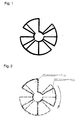
- FIG. 4 the one outlined in FIG. 4 is shown Rotor arrangement is now carried out significantly simplified.
- the two in Figure 4 coupling elements shown, referred to here as a 90 ° rotor and as a 120 ° rotor are now in one piece with the one shown in FIG Coupling element has been merged electrically and mechanically.
- This Coupling element has all the contours of the conductor loops of the two in FIG. 4 shown rotors, but the contours no longer one behind the other but are now arranged side by side, i.e. in the same plane.
- the Indian Figure 1 rotor can be inexpensively manufactured as a simple stamped part become.
Landscapes
- Physics & Mathematics (AREA)
- General Physics & Mathematics (AREA)
- Measurement Of Length, Angles, Or The Like Using Electric Or Magnetic Means (AREA)
- Transmission And Conversion Of Sensor Element Output (AREA)
Applications Claiming Priority (2)
| Application Number | Priority Date | Filing Date | Title |
|---|---|---|---|
| DE10156238 | 2001-11-15 | ||
| DE2001156238 DE10156238A1 (de) | 2001-11-15 | 2001-11-15 | Induktiver Winkelsensor, insbesondere für ein Kraftfahrzeug |
Publications (3)
| Publication Number | Publication Date |
|---|---|
| EP1312889A2 true EP1312889A2 (fr) | 2003-05-21 |
| EP1312889A3 EP1312889A3 (fr) | 2004-08-25 |
| EP1312889B1 EP1312889B1 (fr) | 2008-01-23 |
Family
ID=7705928
Family Applications (1)
| Application Number | Title | Priority Date | Filing Date |
|---|---|---|---|
| EP02025142A Expired - Lifetime EP1312889B1 (fr) | 2001-11-15 | 2002-11-09 | Capteur d'angle inductif en particulier pour une voiture |
Country Status (2)
| Country | Link |
|---|---|
| EP (1) | EP1312889B1 (fr) |
| DE (2) | DE10156238A1 (fr) |
Cited By (8)
| Publication number | Priority date | Publication date | Assignee | Title |
|---|---|---|---|---|
| WO2009095442A1 (fr) * | 2008-01-31 | 2009-08-06 | Hella Kgaa Hueck & Co. | Capteur de couple à induction |
| CN105164501A (zh) * | 2013-03-20 | 2015-12-16 | 舍弗勒技术股份两合公司 | 用于无接触测量角度的方法和角度传感器 |
| US9983045B2 (en) | 2014-08-22 | 2018-05-29 | Ksr Ip Holdings Llc | Inductive sensor |
| US10330499B2 (en) | 2013-05-03 | 2019-06-25 | KSR IP Holdings, LLC | Micro inductive sensor |
| CN112444191A (zh) * | 2019-08-30 | 2021-03-05 | 英飞凌科技股份有限公司 | 感应式角传感器 |
| CN115917261A (zh) * | 2020-06-10 | 2023-04-04 | 海拉有限双合股份公司 | 感应式位置传感器 |
| DE102022131780A1 (de) * | 2022-11-30 | 2024-06-06 | HELLA GmbH & Co. KGaA | Induktiver Drehwinkelsensor |
| US12244183B2 (en) | 2021-09-21 | 2025-03-04 | Advanced Automation Group | Angle sensor device |
Families Citing this family (8)
| Publication number | Priority date | Publication date | Assignee | Title |
|---|---|---|---|---|
| DE102006055049B3 (de) * | 2006-11-22 | 2008-06-12 | Cherry Gmbh | Kombinierter Lenkwinkel- und Drehmomentsensor |
| US7726208B2 (en) | 2006-11-22 | 2010-06-01 | Zf Friedrichshafen Ag | Combined steering angle and torque sensor |
| DE102008012923A1 (de) | 2008-03-06 | 2009-09-10 | Hella Kgaa Hueck & Co. | Induktiver Winkelsensor |
| DE102008012922B4 (de) | 2008-03-06 | 2019-05-29 | HELLA GmbH & Co. KGaA | Induktiver Winkelsensor |
| DE102008020325B4 (de) | 2008-04-23 | 2017-03-16 | Borgwarner Ludwigsburg Gmbh | Winkelsensor |
| EP2120017A1 (fr) | 2008-05-13 | 2009-11-18 | Hella KG Hueck & Co. | Capteur de course de rotation |
| DE102010009497B4 (de) | 2010-02-26 | 2024-06-06 | HELLA GmbH & Co. KGaA | Drehsensor |
| DE102012008699B4 (de) | 2012-04-28 | 2014-04-03 | Wolfgang Kühnel | Verfahren zur Vergrößerung der Meßreichweite einer Vorrichtung zur berührungslosen Messung eines Abstands |
Family Cites Families (4)
| Publication number | Priority date | Publication date | Assignee | Title |
|---|---|---|---|---|
| DE3642607A1 (de) * | 1986-12-13 | 1988-06-23 | Bosch Gmbh Robert | Positionsmesswertgeber |
| DE19738836A1 (de) * | 1997-09-05 | 1999-03-11 | Hella Kg Hueck & Co | Induktiver Winkelsensor |
| GB9811151D0 (en) * | 1998-05-22 | 1998-07-22 | Scient Generics Ltd | Rotary encoder |
| DE19941464A1 (de) * | 1999-09-01 | 2001-03-15 | Hella Kg Hueck & Co | Induktiver Positionssensor |
-
2001
- 2001-11-15 DE DE2001156238 patent/DE10156238A1/de not_active Withdrawn
-
2002
- 2002-11-09 DE DE50211597T patent/DE50211597D1/de not_active Expired - Lifetime
- 2002-11-09 EP EP02025142A patent/EP1312889B1/fr not_active Expired - Lifetime
Cited By (12)
| Publication number | Priority date | Publication date | Assignee | Title |
|---|---|---|---|---|
| WO2009095442A1 (fr) * | 2008-01-31 | 2009-08-06 | Hella Kgaa Hueck & Co. | Capteur de couple à induction |
| US8453518B2 (en) | 2008-01-31 | 2013-06-04 | Hella Kgaa Hueck & Co. | Inductive torque sensor |
| DE102008006865B4 (de) | 2008-01-31 | 2024-02-29 | HELLA GmbH & Co. KGaA | Induktiver Drehmomentsensor |
| CN105164501A (zh) * | 2013-03-20 | 2015-12-16 | 舍弗勒技术股份两合公司 | 用于无接触测量角度的方法和角度传感器 |
| CN105164501B (zh) * | 2013-03-20 | 2017-07-07 | 舍弗勒技术股份两合公司 | 用于无接触测量角度的方法和角度传感器 |
| US10330499B2 (en) | 2013-05-03 | 2019-06-25 | KSR IP Holdings, LLC | Micro inductive sensor |
| US9983045B2 (en) | 2014-08-22 | 2018-05-29 | Ksr Ip Holdings Llc | Inductive sensor |
| CN112444191A (zh) * | 2019-08-30 | 2021-03-05 | 英飞凌科技股份有限公司 | 感应式角传感器 |
| US11592319B2 (en) | 2019-08-30 | 2023-02-28 | Infineon Technologies Ag | Inductive angle sensor |
| CN115917261A (zh) * | 2020-06-10 | 2023-04-04 | 海拉有限双合股份公司 | 感应式位置传感器 |
| US12244183B2 (en) | 2021-09-21 | 2025-03-04 | Advanced Automation Group | Angle sensor device |
| DE102022131780A1 (de) * | 2022-11-30 | 2024-06-06 | HELLA GmbH & Co. KGaA | Induktiver Drehwinkelsensor |
Also Published As
| Publication number | Publication date |
|---|---|
| DE50211597D1 (de) | 2008-03-13 |
| EP1312889B1 (fr) | 2008-01-23 |
| EP1312889A3 (fr) | 2004-08-25 |
| DE10156238A1 (de) | 2003-06-05 |
Similar Documents
| Publication | Publication Date | Title |
|---|---|---|
| EP1081454B1 (fr) | Capteur de position inductif | |
| EP1312889B1 (fr) | Capteur d'angle inductif en particulier pour une voiture | |
| EP3365634B1 (fr) | Capteur d'angle de rotation | |
| EP2240751A1 (fr) | Capteur de couple à induction | |
| EP0909955A2 (fr) | Détecteur angulaire inductif | |
| DE10026019A1 (de) | Induktiver Positionssensor, insbesondere für ein Kraftfahrzeug | |
| DE102013218768A1 (de) | Induktive Positionsmesseinrichtung | |
| DE112008003394T5 (de) | Induktiver Stellungssensor | |
| EP3417245B1 (fr) | Capteur | |
| DE10057773B4 (de) | Näherungsschalter | |
| EP1050744A1 (fr) | Capteur inductif de position linéaire et capteur inductif de rotation | |
| EP2302328B1 (fr) | Couplage d'aimant permanent avec un sensemble de bobines émettrices qui se croisent plusieurs fois | |
| EP0936444B1 (fr) | Dispositif de détection sans contact de la position d'un objet, en particulier d'un arbre de commande d'une boîte de vitesse d'un véhicule | |
| DE102022207287A1 (de) | Induktive Sensoranordnung und Verfahren zur Bestimmung eines Differenzwerts zwischen zwei Bewegungen | |
| DE102007036202A1 (de) | Prüf- und Simulationsschaltung für Magnetfeldsensoren | |
| DE102007017308B4 (de) | Feder-Einheit mit Sensor für den Federweg | |
| DE102006017727A1 (de) | Berührungslose Sensorvorrichtung und Verfahren zur Bestimmung von Eigenschaften einer Welle | |
| WO2021249776A1 (fr) | Capteur inductif de position | |
| DE102004026311A1 (de) | Positionsgeber | |
| DE102011106940A1 (de) | Positionsmesseinrichtung mit Randkompensation | |
| EP0797078A1 (fr) | Capteur inductif pour mesurer l'angle de rotation | |
| WO2017140678A1 (fr) | Capteur | |
| DE102011010682B3 (de) | Spulenanordnung und Sensor | |
| DE19701319C2 (de) | Positionsmeßeinrichtung | |
| DE102008064544B4 (de) | Positions-/Wegmesssystem und Verfahren zur Bestimmung der Position eines Gebers |
Legal Events
| Date | Code | Title | Description |
|---|---|---|---|
| PUAI | Public reference made under article 153(3) epc to a published international application that has entered the european phase |
Free format text: ORIGINAL CODE: 0009012 |
|
| AK | Designated contracting states |
Designated state(s): AT BE BG CH CY CZ DE DK EE ES FI FR GB GR IE IT LI LU MC NL PT SE SK TR |
|
| AX | Request for extension of the european patent |
Extension state: AL LT LV MK RO SI |
|
| PUAL | Search report despatched |
Free format text: ORIGINAL CODE: 0009013 |
|
| AK | Designated contracting states |
Kind code of ref document: A3 Designated state(s): AT BE BG CH CY CZ DE DK EE ES FI FR GB GR IE IT LI LU MC NL PT SE SK TR |
|
| AX | Request for extension of the european patent |
Extension state: AL LT LV MK RO SI |
|
| RAP1 | Party data changed (applicant data changed or rights of an application transferred) |
Owner name: HELLA KGAA HUECK & CO. |
|
| 17P | Request for examination filed |
Effective date: 20050115 |
|
| AKX | Designation fees paid |
Designated state(s): DE ES FR GB IT |
|
| 17Q | First examination report despatched |
Effective date: 20050609 |
|
| GRAP | Despatch of communication of intention to grant a patent |
Free format text: ORIGINAL CODE: EPIDOSNIGR1 |
|
| GRAS | Grant fee paid |
Free format text: ORIGINAL CODE: EPIDOSNIGR3 |
|
| GRAA | (expected) grant |
Free format text: ORIGINAL CODE: 0009210 |
|
| AK | Designated contracting states |
Kind code of ref document: B1 Designated state(s): DE ES FR GB IT |
|
| REG | Reference to a national code |
Ref country code: GB Ref legal event code: FG4D Free format text: NOT ENGLISH |
|
| REF | Corresponds to: |
Ref document number: 50211597 Country of ref document: DE Date of ref document: 20080313 Kind code of ref document: P |
|
| PG25 | Lapsed in a contracting state [announced via postgrant information from national office to epo] |
Ref country code: ES Free format text: LAPSE BECAUSE OF FAILURE TO SUBMIT A TRANSLATION OF THE DESCRIPTION OR TO PAY THE FEE WITHIN THE PRESCRIBED TIME-LIMIT Effective date: 20080504 |
|
| GBV | Gb: ep patent (uk) treated as always having been void in accordance with gb section 77(7)/1977 [no translation filed] | ||
| ET | Fr: translation filed | ||
| PLBE | No opposition filed within time limit |
Free format text: ORIGINAL CODE: 0009261 |
|
| STAA | Information on the status of an ep patent application or granted ep patent |
Free format text: STATUS: NO OPPOSITION FILED WITHIN TIME LIMIT |
|
| 26N | No opposition filed |
Effective date: 20081024 |
|
| PG25 | Lapsed in a contracting state [announced via postgrant information from national office to epo] |
Ref country code: GB Free format text: LAPSE BECAUSE OF FAILURE TO SUBMIT A TRANSLATION OF THE DESCRIPTION OR TO PAY THE FEE WITHIN THE PRESCRIBED TIME-LIMIT Effective date: 20080123 |
|
| REG | Reference to a national code |
Ref country code: FR Ref legal event code: PLFP Year of fee payment: 14 |
|
| REG | Reference to a national code |
Ref country code: FR Ref legal event code: PLFP Year of fee payment: 15 |
|
| REG | Reference to a national code |
Ref country code: FR Ref legal event code: PLFP Year of fee payment: 16 |
|
| REG | Reference to a national code |
Ref country code: DE Ref legal event code: R081 Ref document number: 50211597 Country of ref document: DE Owner name: HELLA GMBH & CO. KGAA, DE Free format text: FORMER OWNER: HELLA KGAA HUECK & CO., 59557 LIPPSTADT, DE |
|
| REG | Reference to a national code |
Ref country code: FR Ref legal event code: PLFP Year of fee payment: 17 |
|
| PGFP | Annual fee paid to national office [announced via postgrant information from national office to epo] |
Ref country code: FR Payment date: 20210930 Year of fee payment: 20 |
|
| PGFP | Annual fee paid to national office [announced via postgrant information from national office to epo] |
Ref country code: DE Payment date: 20210923 Year of fee payment: 20 |
|
| PGFP | Annual fee paid to national office [announced via postgrant information from national office to epo] |
Ref country code: IT Payment date: 20211012 Year of fee payment: 20 |
|
| REG | Reference to a national code |
Ref country code: DE Ref legal event code: R071 Ref document number: 50211597 Country of ref document: DE |