EP1312896A1 - Kombination aus Lichtleiter und Schutzkappe - Google Patents
Kombination aus Lichtleiter und Schutzkappe Download PDFInfo
- Publication number
- EP1312896A1 EP1312896A1 EP02257267A EP02257267A EP1312896A1 EP 1312896 A1 EP1312896 A1 EP 1312896A1 EP 02257267 A EP02257267 A EP 02257267A EP 02257267 A EP02257267 A EP 02257267A EP 1312896 A1 EP1312896 A1 EP 1312896A1
- Authority
- EP
- European Patent Office
- Prior art keywords
- refractive index
- light
- housing
- optical
- Prior art date
- Legal status (The legal status is an assumption and is not a legal conclusion. Google has not performed a legal analysis and makes no representation as to the accuracy of the status listed.)
- Withdrawn
Links
- 230000003287 optical effect Effects 0.000 title claims description 50
- 230000001681 protective effect Effects 0.000 title description 3
- 239000007787 solid Substances 0.000 claims description 9
- 230000005540 biological transmission Effects 0.000 claims description 3
- 230000000737 periodic effect Effects 0.000 claims description 2
- 230000003760 hair shine Effects 0.000 claims 1
- 239000000356 contaminant Substances 0.000 description 6
- 238000000576 coating method Methods 0.000 description 4
- 239000011248 coating agent Substances 0.000 description 3
- 239000000428 dust Substances 0.000 description 2
- 238000000034 method Methods 0.000 description 2
- 238000012986 modification Methods 0.000 description 2
- 230000004048 modification Effects 0.000 description 2
- 230000004075 alteration Effects 0.000 description 1
- 238000005452 bending Methods 0.000 description 1
- 238000013034 coating degradation Methods 0.000 description 1
- 238000011109 contamination Methods 0.000 description 1
- 230000007423 decrease Effects 0.000 description 1
- 230000003292 diminished effect Effects 0.000 description 1
- -1 dirt Substances 0.000 description 1
- 239000004519 grease Substances 0.000 description 1
- 239000000463 material Substances 0.000 description 1
- 230000001737 promoting effect Effects 0.000 description 1
- 239000011253 protective coating Substances 0.000 description 1
- 239000012780 transparent material Substances 0.000 description 1
Images



Classifications
-
- G—PHYSICS
- G02—OPTICS
- G02B—OPTICAL ELEMENTS, SYSTEMS OR APPARATUS
- G02B6/00—Light guides; Structural details of arrangements comprising light guides and other optical elements, e.g. couplings
- G02B6/24—Coupling light guides
- G02B6/26—Optical coupling means
- G02B6/35—Optical coupling means having switching means
- G02B6/351—Optical coupling means having switching means involving stationary waveguides with moving interposed optical elements
- G02B6/353—Optical coupling means having switching means involving stationary waveguides with moving interposed optical elements the optical element being a shutter, baffle, beam dump or opaque element
-
- G—PHYSICS
- G01—MEASURING; TESTING
- G01D—MEASURING NOT SPECIALLY ADAPTED FOR A SPECIFIC VARIABLE; ARRANGEMENTS FOR MEASURING TWO OR MORE VARIABLES NOT COVERED IN A SINGLE OTHER SUBCLASS; TARIFF METERING APPARATUS; MEASURING OR TESTING NOT OTHERWISE PROVIDED FOR
- G01D5/00—Mechanical means for transferring the output of a sensing member; Means for converting the output of a sensing member to another variable where the form or nature of the sensing member does not constrain the means for converting; Transducers not specially adapted for a specific variable
- G01D5/26—Mechanical means for transferring the output of a sensing member; Means for converting the output of a sensing member to another variable where the form or nature of the sensing member does not constrain the means for converting; Transducers not specially adapted for a specific variable characterised by optical transfer means, i.e. using infrared, visible, or ultraviolet light
- G01D5/32—Mechanical means for transferring the output of a sensing member; Means for converting the output of a sensing member to another variable where the form or nature of the sensing member does not constrain the means for converting; Transducers not specially adapted for a specific variable characterised by optical transfer means, i.e. using infrared, visible, or ultraviolet light with attenuation or whole or partial obturation of beams of light
- G01D5/34—Mechanical means for transferring the output of a sensing member; Means for converting the output of a sensing member to another variable where the form or nature of the sensing member does not constrain the means for converting; Transducers not specially adapted for a specific variable characterised by optical transfer means, i.e. using infrared, visible, or ultraviolet light with attenuation or whole or partial obturation of beams of light the beams of light being detected by photocells
- G01D5/347—Mechanical means for transferring the output of a sensing member; Means for converting the output of a sensing member to another variable where the form or nature of the sensing member does not constrain the means for converting; Transducers not specially adapted for a specific variable characterised by optical transfer means, i.e. using infrared, visible, or ultraviolet light with attenuation or whole or partial obturation of beams of light the beams of light being detected by photocells using displacement encoding scales
- G01D5/34707—Scales; Discs, e.g. fixation, fabrication, compensation
- G01D5/34715—Scale reading or illumination devices
-
- G—PHYSICS
- G02—OPTICS
- G02B—OPTICAL ELEMENTS, SYSTEMS OR APPARATUS
- G02B6/00—Light guides; Structural details of arrangements comprising light guides and other optical elements, e.g. couplings
- G02B6/10—Light guides; Structural details of arrangements comprising light guides and other optical elements, e.g. couplings of the optical waveguide type
Definitions
- the present invention relates generally to the field of optics, and more specifically to a combined optical light pipe and protective enclosure.
- Total internal reflection is an optical phenomenon that occurs when light rays are reflected at the boundary between two transparent media, each having a different index of refraction.
- Light rays passing through a first transparent medium of relatively high refractive index (optically dense) and arriving at the interface with a second transparent medium of lower refractive index (optically rarer) may be completely reflected within the optically dense medium.
- Total internal reflection depends on the difference between the refractive indices of the two media and the angle of incidence of the light ray at the interface.
- the critical angle for total internal reflection is defined as the minimum angle at which a light ray striking the surface of an optically rarer medium will be reflected instead of refracted. Although the reflection is total, the light ray actually penetrates a small distance into the rarer medium.
- Total internal reflection can be mathematically expressed by Snell's Law.
- â must be at least 90 degrees.
- â 90 degrees
- the beam is reflected parallel to the interface between the two media. If â is greater than 90 degrees, the beam is totally reflected back through the first optically dense medium.
- the critical angle for total internal reflection, á CRIT is thus: sin á CRIT /sin 90° > n 2 /n 1 or á CRIT > sin -1 n 2 /n 1
- a light pipe is a kind of optical waveguide that utilizes the phenomena of total internal reflection to direct light from one point to another.
- Light pipes are convenient for bending light, directing light around corners, splitting a light beam for delivery to a plurality of destinations, precisely directing light from a specific source to a specific destination, transmitting light signals through environments otherwise hostile to light transmission, insulating light beams from outside interference or scattering, and like applications. Since light pipes operate by the principle of total internal reflection, it is important that the interfacial surface of the light pipe be kept clean. For most light pipes, the optically rarer medium is air.
- the n 2 /n 1 value increases and the critical angle á CRIT accordingly increases, allowing for light to escape or "leak" from the light pipe, thereby reducing its efficiency and utility. In extreme cases, optical leakage can result in the catastrophic failure of the light pipe. Therefore, it is necessary to protect the light pipe from such contaminants.
- One embodiment of the present invention is a housing having an optically transparent internal volume of a first refractive index with an optical entry point defined on the surface of the optically transparent volume and an optical transit point defined within the optically transparent volume, and a first pocket formed in the optically transparent volume.
- the first pocket defines a first three-dimensional negative object within the optically transparent volume having a second refractive index substantially less than the first refractive index.
- the first pocket is substantially encased by the optically transparent volume and is shaped to reflect a beam of light passing through the optical entry point and incident upon the first pocket to the optical transit point.
- One object of the present invention is to provide an improved light pipe. Related objects and advantages of the present invention will be apparent from the following description.
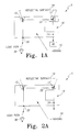
- FIGs. 1A, 1B, 2A, and 2B illustrate a first embodiment of the present invention, a light pipe 5 formed within a substantially solid housing 10.
- the housing 10 is preferably formed from a volume of optically transparent material, such as plastic, having a refractive index substantially greater than unity.
- At least one pocket or cavity 12 is formed within the housing 10.
- Each pocket 12 may be envisioned as a three-dimensional negative object formed within the confines of the housing 10 (see FIGs. 1B-C and 2B-C).
- Each pocket 12 is preferably completely encased within the housing 10 (see FIGs. 1B and 2B), although a pocket-forming process may necessitate a portion of the pocket 12 to intersect with the housing surface (see FIGs. 1C and 2C).
- the pocket 12 may have any convenient shape, although preferred pocket shapes are regular geometric forms having geometrical cross sectional shapes such as triangles (see FIGs. 1A-C) or rectangles (see FIGs. 2A-C).
- the pocket 12 preferably includes at least one substantially flat reflecting interfacial surface 14 positioned to redirect incident light through the housing 10.
- the substantially flat reflecting interfacial surface 14 is preferably positioned entirely within the boundaries of the housing 10, such that any external contaminants, such as dirt, dust, body oil, grease, or the like cannot come into contact therewith.
- the refractive index of the pocket 12 is preferably close to 1.0 or unity, and is more preferably substantially equal to unity.
- the pocket 12 is preferably filled with an optically rare optical medium, for example a gas (such as air) or a partial vacuum, but may be filled with any relatively optically rare medium.
- the refractive index of the housing 10 is preferably at least about 1.2 and is more preferably about 1.5. However, the housing 10 may be selected to have any convenient refractive index such that light passing therethrough is totally internally reflected by the pocket 12.
- the housing 10 is preferably shaped to provide at least one recess or hollow 18 into which an object to be housed may be placed.
- the recess 18 is at least partially enclosed by the housing 10, such that the interior of the recess 18, as well as an object placed therein, enjoys a modicum of protection from the outside environment.
- the housing 10 further includes an optical entry point 20 defined on or below its surface, at least one optical transit point 22 defined within the housing 10, and an optical exit point 24 defined on or in the housing 10.
- the optical entry point 20 is preferably a point positioned between a light source 30 positioned exterior to the housing 10 and the reflective interfacial surface 14 of the first pocket 12, such that a light beam shining from the light source 30 through the optical entry point 20 strikes the first pocket 12 and is totally internally reflected therefrom toward a desired destination.
- a light beam travelling from a pre-positioned light source 30 through the optical entry point 20 and striking the reflective interfacial surface 14 of the first pocket 12 is redirected through a known angle towards a predetermined target. This target is designated the optical transit point 22 for convenience.
- Light emerging through the optical exit point 24 may be directed towards some light detecting device, such as a human eye or a photodetector 40.
- the housing 10 is preferably at least partially coated with an opaque material (or at least partially encased in an opaque casing) to minimize optical interference from external light sources.
- a second pocket 12' is positioned such that the optical transit point 22 is immediately adjacent its reflective interfacial surface 14.
- the light beam from the first pocket 12 intersects the optical transit point 22 and is then redirected via total internal reflection by the second pocket 12'.
- the optical exit point 24 is defined to be a point in or on the housing 10 through which the light beam passes after it has been redirected for the last time by a pocket 12.
- the optical exit point 24 is on a path between the second pocket 12', the recess 18, and the exterior of the housing 10. The light beam, if allowed to travel uninterrupted through the recess 18, therefore traces a path from the light source 30 to the first pocket 12, the second pocket 12', across the recess 18, and out of the housing 10.
- the reflective surfaces 14 of the light pipe 5 are all located within its interior, those reflective surfaces 14 are well shielded from dust and other like contaminants and remain substantially clean. Therefore, the reflective surfaces 14 are not degraded by contamination and the capacity for total internal reflection within the light pipe 5 is not diminished over time.
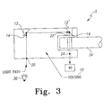
- FIGs. 3 and 4 illustrate a third embodiment of the present invention, a light pipe 5 as described generally above, but further comprising an optical device positioned in the recess 18.
- the optical device is the rotary encoder wheel 34 portion of an automotive clockspring 36.
- the encoder wheel 34 has a number of linear apertures 38 formed therethrough and positioned near the edge of the wheel 34.
- a portion of the wheel 34 is positioned in the recess 18, such that rotation of the wheel 34 about its axis rotates the linear apertures 38 through the recess 18.
- the wheel 34 is further positioned such that each linear aperture 38 rotates through a the line drawn between the optical transit point 22 and the optical exit point 24.
- the linear apertures 38 are further oriented such that their major axes are parallel with a line drawn between the optical transit point 22 and the optical exit point 24, and are preferably colinear with such a line.
- apertures 38 are alternately presented to the recess 18 such that a light beam reflected from a pocket 12' periodically passes through an aperture 38, such that to an observer on the other side of the aperture 18 from the pocket 12' the periodic transmission of the light beam through an aperture 38 would appear as a flicker.
- a photodetector 40 may be positioned opposite the encoder wheel 34 from the optical exit point 24 and in the path of the light beam periodically passing through an aperture 38 to count the flickers. By counting the 'flickers', such information as the degree of rotation and the rotation speed of the encoder wheel 34, and of any mechanical device the encoder wheel 34 is coupled to (such as a steering column), may be determined.
Landscapes
- Physics & Mathematics (AREA)
- General Physics & Mathematics (AREA)
- Optics & Photonics (AREA)
- Light Guides In General And Applications Therefor (AREA)
- Optical Transform (AREA)
Applications Claiming Priority (2)
| Application Number | Priority Date | Filing Date | Title |
|---|---|---|---|
| US09/992,320 US6752526B2 (en) | 2001-11-19 | 2001-11-19 | Combined optical light pipe and protective enclosure |
| US992320 | 2001-11-19 |
Publications (1)
| Publication Number | Publication Date |
|---|---|
| EP1312896A1 true EP1312896A1 (de) | 2003-05-21 |
Family
ID=25538188
Family Applications (1)
| Application Number | Title | Priority Date | Filing Date |
|---|---|---|---|
| EP02257267A Withdrawn EP1312896A1 (de) | 2001-11-19 | 2002-10-18 | Kombination aus Lichtleiter und Schutzkappe |
Country Status (2)
| Country | Link |
|---|---|
| US (1) | US6752526B2 (de) |
| EP (1) | EP1312896A1 (de) |
Cited By (1)
| Publication number | Priority date | Publication date | Assignee | Title |
|---|---|---|---|---|
| GB2390897A (en) * | 2002-04-11 | 2004-01-21 | Agilent Technologies Inc | Optical encoder device |
Families Citing this family (4)
| Publication number | Priority date | Publication date | Assignee | Title |
|---|---|---|---|---|
| DE10325108A1 (de) * | 2003-06-03 | 2005-01-05 | Trw Automotive Electronics & Components Gmbh & Co. Kg | Optoelektronischer Drehwinkelsensor |
| US7352938B2 (en) * | 2004-06-14 | 2008-04-01 | Adc Telecommunications, Inc. | Drive for system for processing fiber optic connectors |
| US7274856B2 (en) * | 2004-06-30 | 2007-09-25 | Lexmark International, Inc. | Waveguide apparatus and method for laser welding |
| JP2009192873A (ja) * | 2008-02-15 | 2009-08-27 | Seiko Epson Corp | 光源装置、画像表示装置及びモニタ装置 |
Citations (5)
| Publication number | Priority date | Publication date | Assignee | Title |
|---|---|---|---|---|
| US5569912A (en) * | 1993-09-30 | 1996-10-29 | U.S. Philips Corporation | Optical velocity measuring with efficient use of radiation passing through patterns on discs |
| DE19711564A1 (de) * | 1997-03-20 | 1998-10-01 | Inst Mikrotechnik Mainz Gmbh | Optisches Schaltelement |
| EP1069025A2 (de) * | 1999-07-15 | 2001-01-17 | Valeo Schalter und Sensoren GmbH | Lenkstockmodul mit Lenkwinkelsensor und geringer Empfindlichkeit des Lenkwinkelsensors gegenüber Rundlauffehlern der Lenksäule |
| EP1108976A1 (de) * | 1999-12-15 | 2001-06-20 | Valeo Schalter und Sensoren GmbH | Lenkwinkelsensor |
| EP1111347A1 (de) * | 1999-12-15 | 2001-06-27 | Brown & Sharpe Tesa S.A. | Positionsgeber |
Family Cites Families (11)
| Publication number | Priority date | Publication date | Assignee | Title |
|---|---|---|---|---|
| US3609960A (en) * | 1968-11-28 | 1971-10-05 | Alduc Sa | Timepiece dial |
| US4625262A (en) * | 1983-07-08 | 1986-11-25 | Yazaki Corporation | Pointer illuminating structure in measuring instrument |
| US4980882A (en) * | 1987-04-06 | 1990-12-25 | Storage Technology Corporation Partners Ii | Optical disk for detesting and distinguishing servo tracks from data tracks |
| JPH0635203Y2 (ja) * | 1988-09-27 | 1994-09-14 | アルプス電気株式会社 | 照光用導光体 |
| US5107107A (en) * | 1990-03-30 | 1992-04-21 | The United States Of America As Represented By The Administarator Of The National Aeronautics And Space Administration | Laser optical disk position encoder with active heads |
| US5436805A (en) * | 1992-10-29 | 1995-07-25 | Hughes Aircraft Company | Thermally insulated distributed light network from a central light source |
| IT1281360B1 (it) * | 1995-09-26 | 1998-02-18 | Fiat Ricerche | Sistema di illuminazione a microtelescopio integrato in una lastra trasparente |
| EP0879991A3 (de) * | 1997-05-13 | 1999-04-21 | Matsushita Electric Industrial Co., Ltd. | Beleuchtungssystème |
| GB2331800A (en) * | 1997-11-29 | 1999-06-02 | Ford Motor Co | A light guide arrangement |
| JPH11284803A (ja) * | 1998-03-27 | 1999-10-15 | Citizen Electronics Co Ltd | 線状光源ユニット |
| DE19835972C1 (de) * | 1998-08-08 | 2000-01-20 | Kostal Leopold Gmbh & Co Kg | Optoelektronische Positionserfassungseinrichtung zur absoluten Weg- oder Winkelbestimmung sowie Verwendung einer solchen Einrichtung |
-
2001
- 2001-11-19 US US09/992,320 patent/US6752526B2/en not_active Expired - Fee Related
-
2002
- 2002-10-18 EP EP02257267A patent/EP1312896A1/de not_active Withdrawn
Patent Citations (5)
| Publication number | Priority date | Publication date | Assignee | Title |
|---|---|---|---|---|
| US5569912A (en) * | 1993-09-30 | 1996-10-29 | U.S. Philips Corporation | Optical velocity measuring with efficient use of radiation passing through patterns on discs |
| DE19711564A1 (de) * | 1997-03-20 | 1998-10-01 | Inst Mikrotechnik Mainz Gmbh | Optisches Schaltelement |
| EP1069025A2 (de) * | 1999-07-15 | 2001-01-17 | Valeo Schalter und Sensoren GmbH | Lenkstockmodul mit Lenkwinkelsensor und geringer Empfindlichkeit des Lenkwinkelsensors gegenüber Rundlauffehlern der Lenksäule |
| EP1108976A1 (de) * | 1999-12-15 | 2001-06-20 | Valeo Schalter und Sensoren GmbH | Lenkwinkelsensor |
| EP1111347A1 (de) * | 1999-12-15 | 2001-06-27 | Brown & Sharpe Tesa S.A. | Positionsgeber |
Cited By (4)
| Publication number | Priority date | Publication date | Assignee | Title |
|---|---|---|---|---|
| GB2390897A (en) * | 2002-04-11 | 2004-01-21 | Agilent Technologies Inc | Optical encoder device |
| GB2390897B (en) * | 2002-04-11 | 2005-08-10 | Agilent Technologies Inc | Optical encoder device |
| US6995356B2 (en) | 2002-04-11 | 2006-02-07 | Agilent Technologies, Inc. | Optical encoder device |
| DE10313363B4 (de) * | 2002-04-11 | 2012-08-23 | Avago Technologies Ecbu Ip (Singapore) Pte. Ltd. | Optische Codierervorrichtung |
Also Published As
| Publication number | Publication date |
|---|---|
| US6752526B2 (en) | 2004-06-22 |
| US20030095418A1 (en) | 2003-05-22 |
Similar Documents
| Publication | Publication Date | Title |
|---|---|---|
| CA1120756A (en) | Prism light guide | |
| EP0707713B1 (de) | Hohler Lichtleiter mit prismatischer Oberfläche | |
| US5399876A (en) | Optical point level sensor with lens | |
| US6356675B1 (en) | Fiber optic refractive index monitor | |
| US5923806A (en) | Fiber optics device | |
| TW201629521A (zh) | 光學裝置 | |
| US3466928A (en) | Fiber optic liquid level indicator | |
| TWI433010B (zh) | 光學式觸控顯示裝置 | |
| US6752526B2 (en) | Combined optical light pipe and protective enclosure | |
| JP7339523B2 (ja) | 液滴センサ | |
| EP1899934B1 (de) | Sensoranordnung zur detektion einer flüssigkeit | |
| JPWO2020148979A1 (ja) | 光コネクタ | |
| US4361760A (en) | Two-degree-of-freedom gyro with radiant energy pickoffs | |
| US5903694A (en) | Fiber optics device | |
| CA1257121A (en) | Hyperhemispherical radiation system | |
| Saxe et al. | Progress in the development of prism light guides | |
| CN224216901U (zh) | 光波导组件、近眼显示装置及光学装置 | |
| JPH03111741A (ja) | 光学式センサ | |
| CN120507830A (zh) | 光波导组件、近眼显示装置及光学装置 | |
| US6907182B2 (en) | Optical conductor | |
| CN216310403U (zh) | 紧凑型光学器件 | |
| WO1999006863A1 (fr) | Element optique et appareil d'imagerie l'utilisant | |
| JPS6234036A (ja) | 水滴検出装置 | |
| JP2687723B2 (ja) | 多芯光ロータリージョイント | |
| JPH0110587Y2 (de) |
Legal Events
| Date | Code | Title | Description |
|---|---|---|---|
| PUAI | Public reference made under article 153(3) epc to a published international application that has entered the european phase |
Free format text: ORIGINAL CODE: 0009012 |
|
| AK | Designated contracting states |
Designated state(s): AT BE BG CH CY CZ DE DK EE ES FI FR GB GR IE IT LI LU MC NL PT SE SK TR |
|
| AX | Request for extension of the european patent |
Extension state: AL LT LV MK RO SI |
|
| AKX | Designation fees paid | ||
| REG | Reference to a national code |
Ref country code: DE Ref legal event code: 8566 |
|
| STAA | Information on the status of an ep patent application or granted ep patent |
Free format text: STATUS: THE APPLICATION IS DEEMED TO BE WITHDRAWN |
|
| 18D | Application deemed to be withdrawn |
Effective date: 20031122 |