EP1312899B1 - Kombinationswaage - Google Patents
Kombinationswaage Download PDFInfo
- Publication number
- EP1312899B1 EP1312899B1 EP02024555A EP02024555A EP1312899B1 EP 1312899 B1 EP1312899 B1 EP 1312899B1 EP 02024555 A EP02024555 A EP 02024555A EP 02024555 A EP02024555 A EP 02024555A EP 1312899 B1 EP1312899 B1 EP 1312899B1
- Authority
- EP
- European Patent Office
- Prior art keywords
- dispensing
- articles
- dispensing table
- surface areas
- tables
- Prior art date
- Legal status (The legal status is an assumption and is not a legal conclusion. Google has not performed a legal analysis and makes no representation as to the accuracy of the status listed.)
- Expired - Lifetime
Links
- 238000005303 weighing Methods 0.000 title claims description 58
- 238000005192 partition Methods 0.000 claims description 105
- 230000002093 peripheral effect Effects 0.000 claims description 39
- 230000007246 mechanism Effects 0.000 claims description 23
- 230000005484 gravity Effects 0.000 claims description 8
- 238000005452 bending Methods 0.000 description 26
- 238000011176 pooling Methods 0.000 description 11
- 238000000034 method Methods 0.000 description 8
- 239000002184 metal Substances 0.000 description 7
- 238000003466 welding Methods 0.000 description 6
- 230000000694 effects Effects 0.000 description 5
- 230000009191 jumping Effects 0.000 description 5
- 230000002787 reinforcement Effects 0.000 description 5
- 238000005096 rolling process Methods 0.000 description 5
- 238000010276 construction Methods 0.000 description 2
- 238000013461 design Methods 0.000 description 2
- 238000009434 installation Methods 0.000 description 2
- 238000004519 manufacturing process Methods 0.000 description 2
- 238000012986 modification Methods 0.000 description 2
- 230000004048 modification Effects 0.000 description 2
- 230000001846 repelling effect Effects 0.000 description 2
- 238000004891 communication Methods 0.000 description 1
- 238000005520 cutting process Methods 0.000 description 1
- 230000003247 decreasing effect Effects 0.000 description 1
- 230000001627 detrimental effect Effects 0.000 description 1
- 238000007599 discharging Methods 0.000 description 1
- 230000001939 inductive effect Effects 0.000 description 1
- 230000010355 oscillation Effects 0.000 description 1
- 238000004806 packaging method and process Methods 0.000 description 1
- 238000012545 processing Methods 0.000 description 1
- 230000002940 repellent Effects 0.000 description 1
- 239000005871 repellent Substances 0.000 description 1
- 238000000638 solvent extraction Methods 0.000 description 1
Images





Classifications
-
- G—PHYSICS
- G01—MEASURING; TESTING
- G01G—WEIGHING
- G01G19/00—Weighing apparatus or methods adapted for special purposes not provided for in the preceding groups
- G01G19/387—Weighing apparatus or methods adapted for special purposes not provided for in the preceding groups for combinatorial weighing, i.e. selecting a combination of articles whose total weight or number is closest to a desired value
- G01G19/393—Weighing apparatus or methods adapted for special purposes not provided for in the preceding groups for combinatorial weighing, i.e. selecting a combination of articles whose total weight or number is closest to a desired value using two or more weighing units
Definitions
- the present invention generally relates to a combination weighing apparatus for perfoiming a combination weighing of auticles and, more particularly to a dispensing table assembly employed in such combination weighing apparatus.
- EP 0 070 647 A2 discloses a combination weighing apparatus comprising a conical turntable for receiving and temporarily retaining articles and a dispersing bowl disposed concentrically with respect to the turntable and capable of tortional reciprocative oscillations. Provided about the circumference of the bowl are equally spaced-apart side walls as well as exit portions defined between the adjacent side walls for discharging articles.
- the present invention is intended to provide a combination calculating apparatus employing a dispensing table assembly which is divided into a plurality of dispensing tables with partition walls, each secured to a divided edge of each of the dispensing tables, wherein each of the dispensing tables is so designed as to allow articles to be weighed to be uniformly dispensed even to an area adjacent the partition wall so that the articles can eventually be delivered onto a plurality of troughs uniformly.
- the distributing point referred to above is the point at which the articles to be weighed are distributed and is not always aligned with the point at which the articles being supplied fall.
- each of the dispensing tables has the distributing point defined at a location distant from the partition wall for distributing the articles supplied from above towards a peripheral region of the respective dispensing table and inclined surface areas inclined downwardly from the distributing point towards the partition wall. Accordingly, the articles to be weighed which have fallen onto the dispensing tables are assuredly distributed over the inclined surface areas towards respective regions adjacent the partition walls. This is particularly advantageous in that there is no possibility of shortage of the amount of the articles eventually delivered onto the delivery devices positioned adjacent the partition walls and, therefore, the articles to be weighed can be substantially uniformly distributed to the plural delivery devices.
- the provision of the inclined surface areas inclined downwardly towards the partition walls is effective to allow such some of the articles, once repelled backwardly in contact with the partition walls, to be again repelled towards the partition walls so as to fall along the inclined surface areas towards the partition walls. For this reason, there is no possibility that the amount of the articles adjacent the partition walls will decrease as a result of repellent in contact with the partition walls.
- each of the dispensing tables referred to above may not be always defined at the highest position of the respective dispensing table, provided that it serves as the point at which the articles to be weighed that are supplied from above by the effect of gravity can be distributed.
- the dispensing table has a plurality of downwardly-inclined surface areas defined by a corresponding number of lines of division that extend from the distributing point towards an outer peripheral edge of the dispensing table, wherein at least some of the plural surface areas which deliver some of the articles towards the corresponding delivery devices are inclined at an virtually equal angle with respect to each other.
- each of the dispensing tables is provided with the a plurality of the downwardly-inclined surface areas defined by a corresponding number of the lines of division that extend from the distributing point towards the outer peripheral edge of the respective dispensing table, some of the plural surface areas which deliver some of the articles towards the corresponding delivery devices being inclined at an virtually equal angle with respect to each other, there is no possibility of the articles being biased towards particular surface areas which would occur when each dispensing table has surface areas of different angles of inclination and the articles can therefore be substantially uniformly dispensed.
- the surface areas that adjoin the partition wall lie substantially perpendicular to the partition wall.
- a plurality of vibrating mechanisms operable to vibrate the associated dispensing tables, respectively, are employed and each of the vibrating mechanisms has a center of vibration that is aligned with a center of gravity of the associated dispensing table.
- each of the dispensing tables is stably vibrated substantially about the center of gravity thereof, further uniform dispensing of the articles to be weighed is possible.
- each of the dispensing tables so formed is defined by a combination of surface areas, it is possible to form surface areas appropriate to the various delivery devices and, therefore, there is no possibility of occurrence that the articles are distributed unequally.
- a supply member for supplying the articles to be weighed towards the distributing point is employed and has a center of supply of the articles being positioned above the distributing point.
- the distributing point is defined at a location spaced from the divided edge of the respective dispensing table, it has now become possible to dispose immediately above the respective distributing points the supply members for supplying the articles to be weighed onto the dispensing tables by the effect of gravity, with respective centers of supply aligned with the associated distributing points. Accordingly, with the structure according to the further embodiment, in view of the fact that the articles to be weighed fall towards the distributing points of the associated dispensing tables, the articles to be weighed so supplied can be further uniformly dispensed.
- a top of each of the supply members represents an inverted conical shape.
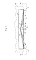
- the combination weighing apparatus is generally identified by 1 and includes a support structure 2 having a support frame 3, a machine body 4 mounted atop the support frame 3, a pair of vibrating mechanisms 5 and 5 mounted atop the machine body 4 at respective locations leftwardly and rightwardly of a vertically extending longitudinal axis of such apparatus 1 for inducing vibrations in a direction up and down, that is, in a vertical direction, a dispensing table assembly made up of a pair of divided dispensing tables 6 and 6 as will be described in detail later and mounted on the machine body 4 through the vibrating mechanisms 5 and 5, and a plurality of vibrating mechanisms, generally identified by 7, arranged radially of the longitudinal axis of the apparatus and positioned adjacent an outer perimeter of the dispensing table assembly (See Fig. 2 ) so as to induce vibrations acting in a direction conforming to the direction of delivery of articles as will be described later.
- a support structure 2 having a support frame 3, a machine body 4 mounted atop the support frame 3, a pair of vibrating
- the combination weighing apparatus 1 also includes a plurality of troughs generally identified by 8 arranged radially of the longitudinal axis of the apparatus 1 for receiving articles dispensed from the dispensing table assembly, a corresponding number of pooling hoppers generally identified by 9 and arranged in a substantially circular row coaxial with the longitudinal axis of the apparatus 1 and positioned immediately below outer ends of the troughs 8, respectively, and a corresponding number of weighing hoppers generally identified by 10 and positioned immediately below the associated pooling hoppers 10.
- the combination weighing apparatus 1 furthermore include guide chutes generally identified by 11, each having an upper end positioned immediately below the associated weighing hopper 10 and inclined downwardly therefrom and generally radially inwardly of the longitudinal axis of the apparatus 1, and collecting chutes generally identified by 12.
- the collecting chutes 12 are generally positioned beneath the divided dispensing tables 6 and 6, respectively, and each of the collecting chutes 12 is positioned below the lower ends of the guide chutes 11 in communication with a group of the guide chutes 11 associated with each divided dispensing table 6.
- the collecting chutes 12 are in turn communicated with a common collecting hopper (not shown) positioned immediately below respective lower open ends of the collecting chutes 12
- Each of the pooling hoppers 9 has a lower end formed with a discharge port that is selectively opened or closed by a respective gate 9a controllably hinged to, for example, the pooling hopper 9 and, similarly, each of the weighing hoppers 10 has a lower end formed with a discharge port that is selectively opened or closed by a respective gate 10a controllably hinged to, for example, the weighing hopper 10.
- the gates 9a of the pooling hoppers 9 and the gates 10a of the weighing hoppers 10 paired with the corresponding pooling hoppers 9 and weighing hoppers 10 are drivingly and controllably coupled with a gate drive mechanism comprised of, for example, link mechanisms.
- the respective gates 10a of some of the weighing hoppers 10 then accommodating the weighed articles having given rise to the optimum combination are opened by the gate drive mechanism to allow those auicles to be discharged downwardly onto some of the guide chutes 11 associated with such some of the weighing hoppers 10.
- the articles so discharged slide downwardly through the guide chutes 11 towards the collecting chutes 12 and 12 and then into the common collecting hopper.
- the articles After the articles have been temporarily stored within the common collecting hopper, they are discharged onto a plurality of delivery devices (not shown) downstream of the collecting hopper and then onto a bagging and/or packaging machine (not shown) in a manner well known those skilled in the art.
- the dispensing table assembly discussed hereinbefore is of a generally round configuration when viewed from top and is substantially divided into two halves, that is, the dispensing tables 6 and 6 along a dividing line drawn to extend across the geometric center of the round shape generally assumed by the dispensing table assembly.
- division of the dispensing table assembly along the dividing line leaves a divided straight edge or a cut edge 6a in each of the resultant dispensing tables 6 and 6 while each of the dispensing tables 6 and 6 represents a generally sector shape.
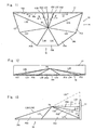
- each of the dispensing tables 6 and 6 has a distributing point T defined at a location distant from the associated divided straight edge 6a and protruding upwardly from a level flush with a generally sector shaped peripheral edge 6b, so that the articles supplied onto the respective dispensing table 6 from above through the aligned supply chute 21 can be distributed generally radially outwardly from the distributing point T.
- each of the dispensing tables 6 and 6 is prepared from a flat metal plate first cut to a predetermined shape and then bent along bending lines L2, L3, L4, L5 and L6 to form a mountain fold and again bent along bending lines L7 and L8 to form a valley fold, with cut edges L1 and L 1 finally jointed together by the use of, for example, a welding technique.
- each of the dispensing tables 6 and 6 has eight inclined flat surface areas P1, P2, P3, P4, P5, P6, P7 and P8 of a generally triangular shape delimited by those bending lines L1 to L8 and inclined downwardly from the distributing point T towards the sector shaped peripheral edge 6b.
- a partition wall 33 is secured to the divided straight edge 6a of each of the dispensing tables 6 and 6 so as to extend upright for preventing some of the articles falling onto one of the dispensing tables 6 and 6 from jumping or rolling onto the other of the dispensing tables 6 and 6.
- This partition wall 33 is fixed to the straight edge 6a and concurrently serves as a reinforcement effective to avoid bending or undulation of the straight edge 6a of each of the dispensing tables 6 and 6.
- the number of the troughs 8 employed corresponds to the total number of the flat inclines surface areas P1 to P8 of the dispensing table assembly and those troughs 8 have their radially inward ends so positioned as to receive the articles moving along the associated inclined flat surface areas P1 to P8.
- each of the dispensing tables 6 and 6 is prepared from the metal plate by the use of any known bending work or a press work so as to have any desired number of flat surface areas, each of the dispensing tables 6 and 6 can have discrete guide slopes that can be easily aligned with the respective trough 8.
- These discrete guide slopes of the dispensing table assembly that is, the inclined flat surface areas of the dispensing tables 6 and 6 provide optimum guide surfaces effective to facilitate generally uniform dispensing of the articles to be weighed and, therefore, the possibility can generally be avoided that one or some of the articles falling onto and traveling along one of the discrete guide slopes apparently towards a particular trough 8 aligned with such one of the guide slopes will move onto the next adjacent guide slope.
- the dispensing table assembly of the particular configuration so tailored in the manner described above is effective to avoid any possible biasing of the articles being dispensed.
- each of the supply chutes 21 and 21 is supported for adjustment in a direction conforming to the longitudinal axis X thereof by means of a drive device so that the respective supply chute 21 can be adjusted in position to achieve an optimum dispensing of the articles onto the associated dispensing table 6.
- the centers of discharge of the supply chutes 21 and 21 referred to above lie in and are represented by the corresponding longitudinal axes X and X, respectively, as shown in Fig. 1 .
- each of the supply chutes 21 and 21 can be positioned with their center of discharge separated from each other, each of the supply chutes 21 and 21 can have a size increased in a direction radially thereof and, therefore, in the illustrated embodiment, each of the supply chutes 21 and 21 have a top opening increased in size while representing a generally inverted conical shape.
- each supply chute 21 and 21 employed in the present invention can have the top opening positioned at a relatively low level and, therefore, the space for installation can be minimized advantageously.
- the transverse support member 23 carrying the supply chutes 21 and 21 has an intermediate portion defined between the supply chutes 21 and 21, and a depending support member 41 is rigidly secured to such intermediate portion of the transverse support member 23 so as to extend downwardly therefrom.
- a lower free end of the depending support member 41 has an anchor brace 42 secured to a lower end thereof.
- a shield sheet 43 employed for each of the dispensing tables 6 and 6 is removably connected at one side edge to the anchor brace 42 and has the opposite side edge held in contact with each of the partition wall 33.
- shield sheets 43 serve to prevent some of the articles discharged from one of the supply chutes 21 and 21 and falling onto one of the dispensing tables 6 and 6 from falling onto the other of the dispensing tables 6 and 6 and, hence, from mixing with the articles discharged from the other of the supply chutes 21 and 21. It is to be noted that in view of the fact that the dispensing tables 6 and 6 are vibrated up and down as hereinbefore described, these shield sheets 43 and 43 are not held tight, but have their inner surfaces slidably held in contact with respective inner surfaces of the partition walls 33 and 33.
- each of the four troughs 8 positioned adjacent and closest to the respective partition walls 33 and 33 has a side wall 8a adjacent the corresponding partition wall 33 that is chosen to have a height greater than the respective side walls of the other troughs 8 so as to stand between the partition walls 33 and 33 as shown in Figs. 2 and 4 , to thereby prevent some of the articles then falling onto the trough 8 associated with one of the dispensing tables 6 and 6 from falling onto the next adjacent trough 8 closest to the other partition wall 33 and associated with the other of the dispensing tables 6 and 6..
- the vibrating mechanisms 5 and 5 referred to hereinbefore are so arranged and so positioned that vibrating centers thereof, that is, respective vibrating shafts 5a and 5a of the vibrating mechanisms 5 and 5 and respective centers of gravity of the dispensing tables 6 and 6 are aligned with each other and also with the longitudinal axes X and X of the supply chutes 21 and 21 as best shown in Fig. 1 .
- This is particularly advantageous in that since the dispensing tables 6 and 6 can be vibrated stably with vibrating forces transmitted to their centers of gravity receiving, a uniform dispensing of the articles to be weighed on the dispensing table assembly can be achieved.
- the vibrating mechanisms 5 and 5 are used to vibrate the respective divided dispensing tables 6 and 6 in a direction up and down. Accordingly, even though some of the articles being dispensed on the dispensing table assembly collide with the partition walls 33 and 33, a component of force tending to repel those articles in a direction away from the partition walls 33 and 33 towards the sector shaped peripheral edges 6b is minimal and, therefore, the possibility can be suppressed that the amount or number of the articles to be weighed which would remain adjacent the partition walls 33 and 33 may be small.
- the articles so supplied onto the dispensing table 6 then vibrated up and down by the corresponding vibrating mechanism 5 are substantially uniformly distributed from the distributing point T towards the inclined flat surface areas P1, P2, P3, P4, P5 and P6 of the dispensing table 6 in respective directions shown by the arrows c1, c2, c3, c4, c5 and c6.
- the dispensing table 6 is vibrated up and down by the vibrating mechanism 5, the articles on those inclined flat surface areas of the dispensing table 6 are positively guided downwardly towards the associated troughs 8.
- the articles to be weighed which have been dispensed on, for example, the inclined flat surface areas P1 and P6 move therealong towards the associated inclined flat surface areas P8 and P7 past the valley folds L8 and L7, respectively. Since the direction of inclination of each of those flat surface areas P8 and P7 is different from that of each of the flat surface areas P 1 and P6, the articles having just moved into the flat surface areas P8 and P7 are then deflected so as to move in respective directions shown by the arrows c8 and c7 along the flat surface areas P8 and P7 before they reach the corresponding troughs 8 and 8 that are positioned immediately below and in alignment with the flat surface areas P8 and P7 through associated portions of the sector shaped peripheral edge 6b of the dispensing table 6.
- the dispensing table 6 is prepared from the metal plate by the use of a bending technique, not only is the dispensing table 6 easy to manufacture, but the cost of manufacture thereof can also be reduced advantageously.
- the dispensing table assembly is comprised of the two, generally sector shaped dispensing tables 56 and 56 having the same configuration and capable of performing the same function and, accordingly, only one of the sector shaped dispensing tables, that is, the left dispensing table 56 as used in the combination weighing apparatus of Fig. 1 will be described in detail for the sake of brevity.
- the dispensing table assembly employed in the practice of the second embodiment of the present invention is of a generally round configuration when viewed from top and is substantially divided into two halves, that is, the dispensing tables 56 and 56 along a dividing line drawn to extend across the geometric center of the round shape generally assumed by the dispensing table assembly as is the case with that in the previously described embodiment.
- the . dispensing table 56 referred to above and described in detail subsequently is of a generally sector configuration in plan view.
- the dispensing table 56 has a distributing point T2 defined at a location distant from the associated divided straight edge 56a and protruding upwardly from a level flush with a generally sector shaped peripheral edge 56b, so that the articles supplied onto the dispensing table 56 from above through the aligned supply chute 21 as shown in Fig. 1 can be distributed generally radially outwardly from the distributing point T2.
- the dispensing table 56 is prepared from a flat metal plate first cut to a predetermined shape and then bent along bending lines L12, L13, L14, L15, L16 and L17 to form a mountain fold with cut edges L11 and L11 jointed by the use of, for example, a welding technique.
- the dispensing table 56 has seven inclined flat surface areas P11, P12, P13, P14, P15, P16 and P17 of a generally triangular shape delimited by those bending lines L11 to L17 and inclined downwardly from the distributing point T2 towards the sector shaped peripheral edge 56b.
- a partition wall 57 is secured to the divided straight edge 56a of the dispensing table 56 so as to extend upright for preventing some of the articles falling onto the dispensing table 56 from jumping or rolling onto the other dispensing table 56.
- This partition wall 57 is fixed to the divided straight edge 56a and concurrently serves as a reinforcement effective to avoid bending or undulation of the straight edge 56a of the dispensing table 56.
- each of the inclined flat surface areas P11 and P17 is so inclined downwardly from the distributing point T2 that the direction of inclination as defined by the direction normal to the line of intersection between each inclined flat surface area P11 and P17 and the geometric horizontal plane extends as indicated by the arrow e1 and e3. Accordingly, the articles to be weighed which have been supplied from the associated supply chute 21 onto the dispensing table 56 generally in alignment with the distributing point T2 can be generally uniformly distributed from the distributing point T2 towards the flat surface areas P11, P12, P13, P14, P15, P16 and P17 and then fall downwardly along those flat surface areas towards the sector shaped peripheral edge 56b.
- the flat surface areas P11 and P17 are inclined upwardly relative to the partition wall 57, some of the articles once distributed onto the flat surface areas P11 and P17 will not ride over the mountain folds L12 and L17 and then onto the adjoining flat surface areas P12 and P16, respectively, but will ride over the lines L12 and L17 only in the vicinity of the sector shaped peripheral edge 56b. Accordingly, without the amount or number of the articles being reduced in the vicinity of the partition wall 57, the articles guided along the flat surface areas P11 and P17 can be positively dispensed onto the associated troughs positioned therebelow.
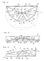
- the dispensing table assembly is of a generally round configuration when viewed from top and is substantially divided into two halves, that is, the dispensing tables 66 and 66 along a dividing line drawn to extend across the geometric center of the round shape generally assumed by the dispensing table assembly as is the case with that in the previously described embodiment.
- the dispensing table now identified by 66 is of a generally sector configuration in plan view.
- the dispensing table 66 has a distributing point T3 defined at a location distant from the associated divided straight edge 66a and protruding upwardly from a level flush with a generally sector shaped peripheral edge 66b, so that the articles supplied onto the dispensing table 66 from above through the aligned supply chute 21 as shown in Fig. 1 can be distributed generally radially outwardly from the distributing point T3.
- the inclined flat surface areas P32 and P38 are inclined to raise upwardly relative to the base edge of the partition wall 77, some of the articles once distributed onto the flat surface areas P32 and P38 will not ride over the mountain fold L33 and L38 and then onto the adjoining flat surface areas P33 and P37, respectively, but are only guided towards respective portions of the sector shaped peripheral edge 77b aligned with the troughs associated with such flat surface areas P32 and P38. Accordingly, without the amount or number of the articles being reduced in the vicinity of the partition wall 77, the articles guided along the flat surface areas P32 and P38 can be positively dispensed onto the associated troughs positioned therebelow.
Landscapes
- Physics & Mathematics (AREA)
- General Physics & Mathematics (AREA)
- Feeding Of Articles To Conveyors (AREA)
- Investigating Strength Of Materials By Application Of Mechanical Stress (AREA)
- Jigging Conveyors (AREA)
- Filling Or Emptying Of Bunkers, Hoppers, And Tanks (AREA)
Claims (8)
- Eine Kombinationswiegevorrichtung, die eine im allgemeinen runde Abgabetischanordnung umfasst, wobei eine Vielzahl von Gegenstandsliefervorrichtungen (8) unterhalb und radial einer äußeren Umfangskante (6b) der Abgabetischanordnung angeordnet ist, um zu wiegende Gegenstände von der Abgabetischanordnung zu empfangen, und wobei eine entsprechende Anzahl von Wiegevorrichtungen (9) unterhalb entsprechender vorderer Enden der Liefervorrichtungen (8) angeordnet sind;
wobei die Abgabetischanordnung eine Vielzahl geteilter Abgabetische (6) umfasst, die erhalten werden, indem die Abgabetischanordnung durch ihr geometrisches Zentrum geteilt wird;
zumindest einer der Abgabetische (6) weist eine Trennungswand (33) auf, die an einer Schnittkante (6a) davon gesichert ist, welche entlang einer Teilungslinie der Abgabetischanordnung belassen wurde, um sich aufrecht zu erstrecken, so dass die abzugebenden Gegenstände auf einem der Abgabetische (6) an einer Bewegung zu den anderen der Abgabetische (6) gehindert werden;
dadurch gekennzeichnet, dass
jeder der Abgabetische (6) einen Verteilungspunkt (T) aufweist, der an einem Ort mit einem Abstand von der Trennungswand (33) definiert ist, um die Gegenstände, die von oberhalb des Abgabetisches (6) bereitgestellt werden, radial auswärts über den Abgabetisch (6) und einen geneigten Oberflächenbereich (P1, P6) zu verteilen, welcher von dem Verteilungspunkt (T) in Richtung der Trennungswand (33) abwärts geneigt ist. - Kombinationswiegevorrichtung nach Anspruch 1, wobei der Abgabetisch (86) eine Vielzahl abwärts geneigter Oberflächenbereiche (P41 - P47) aufweist, die durch eine Vielzahl von Teilungslinien definiert sind, die sich von dem Verteilungspunkt (T) in Richtung einer äußeren Umfangskante (86b) des Abgabetisches (6) erstrecken, wobei einige der mehreren Oberflächenbereiche (P42 - P46), welche einige der Gegenstände in Richtung entsprechender Liefervorrichtungen (8) bewegen, mit einem gleichen Winkel im Verhältnis zueinander geneigt sind.
- Kombinationswiegevorrichtung nach Anspruch 2, wobei die Oberflächengebiete (41, 47), die an die Trennungswand (87) angrenzen, im wesentlichen senkrecht zu der Trennungswand (87) liegen.
- Kombinationswiegevorrichtung nach Anspruch 1, weiterhin eine Vielzahl vibrierender Mechanismen (5) umfassend, die betreibbar sind, um die zugeordneten Abgabetische (6) jeweils zu rütteln, wobei jeder der vibrierenden Mechanismen (5) ein Vibrationszentrum aufweist, welches mit einem Schwerpunkt des zugeordneten Abgabetisches (6) ausgerichtet ist.
- Kombinationswiegevorrichtung nach Anspruch 4, wobei jeder der vibrierenden Mechanismen (5) betreibbar ist, um den zugeordneten Abgabetisch (6) auf- und ab zu rütteln.
- Kombinationswiegevorrichtung nach Anspruch 1, wobei jeder der Abgabetische (6) durch ein gebogenes Plattenbauteil gebildet ist.
- Kombinationswiegevorrichtung nach Anspruch 1, weiterhin ein Zufuhrbauteil (21) zum Zuführen der zu wiegenden Gegenstände in Richtung des Verteilungspunktes (T) umfassend, wobei das Zufuhrbauteil (21) einen Zufuhrmittelpunkt der Gegenstände aufweist, der über dem Verteilungspunkt (T) angeordnet ist.
- Kombinationswiegevorrichtung nach Anspruch 7, wobei ein Oberteil des Zufuhrbauteils (21) eine invertierte konische Form aufweist.
Applications Claiming Priority (2)
| Application Number | Priority Date | Filing Date | Title |
|---|---|---|---|
| JP2001350464A JP3793449B2 (ja) | 2001-11-15 | 2001-11-15 | 組合せ計量装置 |
| JP2001350464 | 2001-11-15 |
Publications (3)
| Publication Number | Publication Date |
|---|---|
| EP1312899A2 EP1312899A2 (de) | 2003-05-21 |
| EP1312899A3 EP1312899A3 (de) | 2006-12-20 |
| EP1312899B1 true EP1312899B1 (de) | 2013-01-30 |
Family
ID=19162962
Family Applications (1)
| Application Number | Title | Priority Date | Filing Date |
|---|---|---|---|
| EP02024555A Expired - Lifetime EP1312899B1 (de) | 2001-11-15 | 2002-11-04 | Kombinationswaage |
Country Status (6)
| Country | Link |
|---|---|
| US (1) | US6756546B2 (de) |
| EP (1) | EP1312899B1 (de) |
| JP (1) | JP3793449B2 (de) |
| CN (1) | CN100354614C (de) |
| MX (1) | MXPA02011266A (de) |
| TW (1) | TW594592B (de) |
Families Citing this family (13)
| Publication number | Priority date | Publication date | Assignee | Title |
|---|---|---|---|---|
| US7572986B2 (en) * | 2004-11-25 | 2009-08-11 | Shozo Kawanishi | Combination weigher |
| JP4809623B2 (ja) * | 2005-04-19 | 2011-11-09 | 大和製衡株式会社 | 混合計量用組合せ秤 |
| US7721897B2 (en) * | 2007-08-16 | 2010-05-25 | Kennecott Utah Copper Llc | Automated sample collection apparatus |
| JP5095477B2 (ja) * | 2008-04-18 | 2012-12-12 | 株式会社イシダ | 組合せ計量装置 |
| EP2273242B1 (de) * | 2008-04-17 | 2019-12-04 | Ishida Co., Ltd. | Kombimessvorrichtung |
| JP5314506B2 (ja) * | 2009-06-05 | 2013-10-16 | 株式会社イシダ | 組合せ計量装置及び電磁フィーダ |
| CN103201601A (zh) * | 2010-10-29 | 2013-07-10 | 株式会社威工 | 容器 |
| CN102818614A (zh) * | 2012-09-07 | 2012-12-12 | 北京贝瑞德生物科技有限公司 | 称重装置及称重方法 |
| CN103528649B (zh) * | 2013-09-18 | 2015-07-29 | 宁波高诚自动化科技有限公司 | 宝塔线质量检测分析系统及方法 |
| AU2015389403A1 (en) * | 2015-03-31 | 2017-09-07 | Yamato Scale Co., Ltd. | Combination weighing device |
| CN108474688B (zh) * | 2016-01-07 | 2020-07-03 | 株式会社石田 | 组合计量装置 |
| JP7086814B2 (ja) * | 2018-10-19 | 2022-06-20 | 大和製衡株式会社 | 組合せ秤の直進フィーダ |
| JP7114190B2 (ja) * | 2018-12-19 | 2022-08-08 | 大和製衡株式会社 | 組合せ計量装置 |
Family Cites Families (6)
| Publication number | Priority date | Publication date | Assignee | Title |
|---|---|---|---|---|
| AU543930B2 (en) | 1981-07-07 | 1985-05-09 | K.K. Ishida Koki Seisakusho | Dispensing feeder |
| JPS59146729U (ja) * | 1983-03-18 | 1984-10-01 | 大和製衡株式会社 | 組合わせ秤の分散供給装置 |
| JPS615431U (ja) * | 1984-06-15 | 1986-01-13 | 株式会社 石田衡器製作所 | 組合せ計量装置の分散テ−ブル構造 |
| US4596405A (en) * | 1984-09-25 | 1986-06-24 | Norma J. Jones | Adjustable length pole |
| JPH0166032U (de) | 1987-10-21 | 1989-04-27 | ||
| JPH0854278A (ja) | 1994-06-08 | 1996-02-27 | Ishida Co Ltd | 組合せ計量装置の分散テーブル |
-
2001
- 2001-11-15 JP JP2001350464A patent/JP3793449B2/ja not_active Expired - Fee Related
-
2002
- 2002-08-16 TW TW091118572A patent/TW594592B/zh not_active IP Right Cessation
- 2002-10-29 US US10/282,102 patent/US6756546B2/en not_active Expired - Fee Related
- 2002-11-04 EP EP02024555A patent/EP1312899B1/de not_active Expired - Lifetime
- 2002-11-14 CN CNB021489769A patent/CN100354614C/zh not_active Expired - Fee Related
- 2002-11-15 MX MXPA02011266A patent/MXPA02011266A/es active IP Right Grant
Also Published As
| Publication number | Publication date |
|---|---|
| EP1312899A2 (de) | 2003-05-21 |
| EP1312899A3 (de) | 2006-12-20 |
| JP3793449B2 (ja) | 2006-07-05 |
| US20030089529A1 (en) | 2003-05-15 |
| CN1420342A (zh) | 2003-05-28 |
| TW594592B (en) | 2004-06-21 |
| US6756546B2 (en) | 2004-06-29 |
| JP2003149036A (ja) | 2003-05-21 |
| CN100354614C (zh) | 2007-12-12 |
| MXPA02011266A (es) | 2006-03-06 |
Similar Documents
| Publication | Publication Date | Title |
|---|---|---|
| EP1312899A2 (de) | Kombinationswaage | |
| US4602709A (en) | Collecting chute for weighed articles discharged from automatic weighing system | |
| EP1164365B1 (de) | KOMBINATIONSWAAGE UND ZäHLVORRICHTUNG | |
| US6360870B1 (en) | Feeding and sorting apparatus | |
| JP3514053B2 (ja) | 部品整送装置 | |
| US7397011B2 (en) | Device for the sorting of flat mailings | |
| JP2015232548A (ja) | 食品片のランク選別方法および装置 | |
| EP1832857B1 (de) | Kombinationswägevorrichtung | |
| CA1304318C (en) | Apparatus for erecting and lining-up moulded parts | |
| US6271485B1 (en) | Article alignment device | |
| US20080060912A1 (en) | Adjustable transfer unit for transferring upright and aligned articles from a first to a second conveyor | |
| EP0074826B1 (de) | Verteilertisch zum Regulieren der Fördergeschwindigkeit von Artikeln | |
| GB2098589A (en) | Apparatus for orientating articles such as bottles and orientating means therefor | |
| US4570727A (en) | Collection chute for automatic weighing apparatus | |
| EP0101313A2 (de) | Methode und Apparat zum Sammeln von gewogenen und von einem kombinatorischen Wägesystem ausgeschütteten Artikeln | |
| US6398461B1 (en) | Container handling system | |
| US20040262202A1 (en) | System for producing packages of items of a predetermined collective weight | |
| JP2579347Y2 (ja) | 組合せ秤の物品供給装置 | |
| EP0107478B1 (de) | Verteilvorrichtung zur Abgabe in automatische Wägeapparate | |
| DE60008761T2 (de) | Ein fördersystem mit einer verschiebvorrichtung für artikel zwischen parallelen förderern | |
| JPH10226410A (ja) | 缶・びん類選別用振動篩 | |
| US20040245150A1 (en) | Extended sorting machine | |
| JPH0658328U (ja) | 自動計量装置の集合シュート | |
| JP3242556U (ja) | 組合せ計量装置 | |
| EP0272666B1 (de) | Wiegevorrichtung |
Legal Events
| Date | Code | Title | Description |
|---|---|---|---|
| PUAI | Public reference made under article 153(3) epc to a published international application that has entered the european phase |
Free format text: ORIGINAL CODE: 0009012 |
|
| AK | Designated contracting states |
Designated state(s): AT BE BG CH CY CZ DE DK EE ES FI FR GB GR IE IT LI LU MC NL PT SE SK TR |
|
| AX | Request for extension of the european patent |
Extension state: AL LT LV MK RO SI |
|
| PUAL | Search report despatched |
Free format text: ORIGINAL CODE: 0009013 |
|
| AK | Designated contracting states |
Kind code of ref document: A3 Designated state(s): AT BE BG CH CY CZ DE DK EE ES FI FR GB GR IE IT LI LU MC NL PT SE SK TR |
|
| AX | Request for extension of the european patent |
Extension state: AL LT LV MK RO SI |
|
| 17P | Request for examination filed |
Effective date: 20070214 |
|
| AKX | Designation fees paid |
Designated state(s): DE FR GB IT |
|
| 17Q | First examination report despatched |
Effective date: 20100302 |
|
| GRAP | Despatch of communication of intention to grant a patent |
Free format text: ORIGINAL CODE: EPIDOSNIGR1 |
|
| GRAS | Grant fee paid |
Free format text: ORIGINAL CODE: EPIDOSNIGR3 |
|
| GRAA | (expected) grant |
Free format text: ORIGINAL CODE: 0009210 |
|
| AK | Designated contracting states |
Kind code of ref document: B1 Designated state(s): DE FR GB IT |
|
| REG | Reference to a national code |
Ref country code: GB Ref legal event code: FG4D |
|
| REG | Reference to a national code |
Ref country code: DE Ref legal event code: R096 Ref document number: 60244471 Country of ref document: DE Effective date: 20130328 |
|
| PLBE | No opposition filed within time limit |
Free format text: ORIGINAL CODE: 0009261 |
|
| STAA | Information on the status of an ep patent application or granted ep patent |
Free format text: STATUS: NO OPPOSITION FILED WITHIN TIME LIMIT |
|
| PG25 | Lapsed in a contracting state [announced via postgrant information from national office to epo] |
Ref country code: IT Free format text: LAPSE BECAUSE OF FAILURE TO SUBMIT A TRANSLATION OF THE DESCRIPTION OR TO PAY THE FEE WITHIN THE PRESCRIBED TIME-LIMIT Effective date: 20130130 |
|
| 26N | No opposition filed |
Effective date: 20131031 |
|
| PGFP | Annual fee paid to national office [announced via postgrant information from national office to epo] |
Ref country code: DE Payment date: 20131121 Year of fee payment: 12 Ref country code: GB Payment date: 20131120 Year of fee payment: 12 |
|
| REG | Reference to a national code |
Ref country code: DE Ref legal event code: R097 Ref document number: 60244471 Country of ref document: DE Effective date: 20131031 |
|
| REG | Reference to a national code |
Ref country code: FR Ref legal event code: ST Effective date: 20140731 |
|
| PG25 | Lapsed in a contracting state [announced via postgrant information from national office to epo] |
Ref country code: FR Free format text: LAPSE BECAUSE OF NON-PAYMENT OF DUE FEES Effective date: 20131202 |
|
| REG | Reference to a national code |
Ref country code: DE Ref legal event code: R119 Ref document number: 60244471 Country of ref document: DE |
|
| GBPC | Gb: european patent ceased through non-payment of renewal fee |
Effective date: 20141104 |
|
| PG25 | Lapsed in a contracting state [announced via postgrant information from national office to epo] |
Ref country code: DE Free format text: LAPSE BECAUSE OF NON-PAYMENT OF DUE FEES Effective date: 20150602 Ref country code: GB Free format text: LAPSE BECAUSE OF NON-PAYMENT OF DUE FEES Effective date: 20141104 |