EP1312954B1 - Faseroptischer Steckerstift - Google Patents
Faseroptischer Steckerstift Download PDFInfo
- Publication number
- EP1312954B1 EP1312954B1 EP01309628A EP01309628A EP1312954B1 EP 1312954 B1 EP1312954 B1 EP 1312954B1 EP 01309628 A EP01309628 A EP 01309628A EP 01309628 A EP01309628 A EP 01309628A EP 1312954 B1 EP1312954 B1 EP 1312954B1
- Authority
- EP
- European Patent Office
- Prior art keywords
- fiber
- ferrule
- insertion hole
- hole
- optical
- Prior art date
- Legal status (The legal status is an assumption and is not a legal conclusion. Google has not performed a legal analysis and makes no representation as to the accuracy of the status listed.)
- Expired - Lifetime
Links
- 239000000835 fiber Substances 0.000 title claims abstract description 239
- 238000003780 insertion Methods 0.000 claims abstract description 77
- 230000037431 insertion Effects 0.000 claims abstract description 77
- 239000013307 optical fiber Substances 0.000 claims abstract description 61
- 230000013011 mating Effects 0.000 claims abstract description 3
- 239000000853 adhesive Substances 0.000 claims description 57
- 230000003287 optical effect Effects 0.000 claims description 25
- 230000001105 regulatory effect Effects 0.000 claims description 6
- 230000007423 decrease Effects 0.000 claims description 5
- 238000000034 method Methods 0.000 claims 1
- 239000000945 filler Substances 0.000 description 8
- 239000002245 particle Substances 0.000 description 5
- 238000010276 construction Methods 0.000 description 3
- 229920001187 thermosetting polymer Polymers 0.000 description 3
- 239000004734 Polyphenylene sulfide Substances 0.000 description 2
- 230000000694 effects Effects 0.000 description 2
- 238000012986 modification Methods 0.000 description 2
- 230000004048 modification Effects 0.000 description 2
- 229920000069 polyphenylene sulfide Polymers 0.000 description 2
- 229920005989 resin Polymers 0.000 description 2
- 239000011347 resin Substances 0.000 description 2
- 229920003002 synthetic resin Polymers 0.000 description 2
- 239000000057 synthetic resin Substances 0.000 description 2
- 229920005992 thermoplastic resin Polymers 0.000 description 2
- 229920000106 Liquid crystal polymer Polymers 0.000 description 1
- 239000004977 Liquid-crystal polymers (LCPs) Substances 0.000 description 1
- 239000003822 epoxy resin Substances 0.000 description 1
- 229920000647 polyepoxide Polymers 0.000 description 1
- 239000004065 semiconductor Substances 0.000 description 1
Images

Classifications
-
- G—PHYSICS
- G02—OPTICS
- G02B—OPTICAL ELEMENTS, SYSTEMS OR APPARATUS
- G02B6/00—Light guides; Structural details of arrangements comprising light guides and other optical elements, e.g. couplings
- G02B6/24—Coupling light guides
- G02B6/36—Mechanical coupling means
- G02B6/38—Mechanical coupling means having fibre to fibre mating means
- G02B6/3807—Dismountable connectors, i.e. comprising plugs
- G02B6/3873—Connectors using guide surfaces for aligning ferrule ends, e.g. tubes, sleeves, V-grooves, rods, pins, balls
- G02B6/3885—Multicore or multichannel optical connectors, i.e. one single ferrule containing more than one fibre, e.g. ribbon type
-
- G—PHYSICS
- G02—OPTICS
- G02B—OPTICAL ELEMENTS, SYSTEMS OR APPARATUS
- G02B6/00—Light guides; Structural details of arrangements comprising light guides and other optical elements, e.g. couplings
- G02B6/24—Coupling light guides
- G02B6/36—Mechanical coupling means
- G02B6/38—Mechanical coupling means having fibre to fibre mating means
- G02B6/3807—Dismountable connectors, i.e. comprising plugs
- G02B6/3833—Details of mounting fibres in ferrules; Assembly methods; Manufacture
- G02B6/3855—Details of mounting fibres in ferrules; Assembly methods; Manufacture characterised by the method of anchoring or fixing the fibre within the ferrule
- G02B6/3861—Adhesive bonding
Definitions
- the present invention relates to a ferrule for a multi-connector used for a connecting portion of optical fibers in optical communications and a connecting portion of optical modules such as optical semiconductors and, more particularly, to a ferrule for an MT connector.
- a ferrule for a multi-connector which is installed at the end of a plurality of optical fibers and is used for connection between the optical fibers, is molded using a thermosetting resin or a thermoplastic resin.
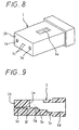
- a ferrule 1 shown in FIG. 8 is provided with two alignment pin holes 1a in which alignment pins for positioning with respect to another ferrule of the same construction are inserted, and two fiber holes 1c which are formed at a predetermined interval between the alignment pin holes 1a and are open to a ferrule end face 1b so that optical fibers are inserted therein.
- the ferrule 1 is also provided with a boot insertion hole 1d which is open to a rear end face, and an adhesive agent inserting window 1e which is formed at a substantially central portion perpendicularly to the boot insertion hole 1d and is open to a top face of the ferrule 1.
- the ferrule 1 is formed with a fiber guide hole 1f located between the fiber hole 1c and the adhesive agent inserting window 1e, and a U-sbaped groove 1g located adjacent to the fiber guide hole 1f.
- the ferrule 1 is assembled into a multi-connector in the following way: An optical fiber, for example, an optical ribbon fiber with fibers separated is inserted through the boot insertion hole 1d, and the optical fibers are inserted into the fiber holes 1c through the U-shaped grooves 1g and the fiber guide holes 1f. Then, an adhesive agent is poured through the adhesive agent inserting window 1e to fix the optical fibers. The extending portion of the optical ribbon fiber is protected by a boot inserted into the rear part of the ferrule 1.
- An optical fiber for example, an optical ribbon fiber with fibers separated is inserted through the boot insertion hole 1d, and the optical fibers are inserted into the fiber holes 1c through the U-shaped grooves 1g and the fiber guide holes 1f.
- an adhesive agent is poured through the adhesive agent inserting window 1e to fix the optical fibers.
- the extending portion of the optical ribbon fiber is protected by a boot inserted into the rear part of the ferrule 1.
- the conventional ferrule shown in FIGS. 8 and 9 is provided with step portions S1 and S2 at the substantially central portions of the boots insertion hole 1d.
- the ferrule 1 has a problem in that when optical fibers are inserted into the fiber holes 1c through the boot insertion hole 1d, the U-shaped grooves 1g, and the fiber guide holes 1f to assemble an optical connector, the optical fiber is liable to abut on the step portions S1 and S2, so that the work efficiency is low, and in the worst case, the optical fiber is broken.
- EP-A-1061390 discloses a ferrule having a plurality of fiber fixed holes for optical fibers to be inserted into.
- Each of the fiber fixed holes has an optical fiber introducing hole for guiding the optical fiber, a minute hole connected to the optical fiber introducing hole for inserting the optical fiber, and a fiber ribbon insertion hole connected with the optical fiber introducing hole to receive the sheathed portion of a multiple-fiber optical fiber ribbon.
- a connecting portion of the optical fiber introducing hole and the fiber ribbon insertion hole is tapered.
- the fiber ribbon insertion hole forms a pool at its opening for an adhesive agent for fixing the optical fibers.
- CH-A-687105 discloses a connector having cooperating plug and socket halves. Each half has a plurality of fiber fixed holes which each have a fiber insertion hole.
- JP-A-9-203825 discloses a connector having adjoining parallel grooves for receiving sheathed portions of optical fibers.
- DE-A-25 16 662 discloses a ferrule having a plurality of fiber fixed holes.
- Each fiber fixed hole has a fiber guide hole formed so that its diameter decreases from an adjoining fiber insertion hole at one end to an adjoining fiber hole at the opposite end.
- JP-A-01-017010 discloses ferrules which each have a fiber insertion hole that forms a pool at its opening for receiving adhesive agents for fixing an optical cable terminal. Adhesive agents are sucked from the ferrules so that the adhesive agents are spread into all parts of the ferrules and the ferrules are inserted to the optical cable terminals.
- the present invention has been made to solve the above problems, and accordingly an object thereof is to provide a ferrule which has a fiber fixed hole into which an optical fiber can be inserted easily without being broken and which can provide a sufficient fiber bonding strength, and which can restrain variations in connection loss caused by the temperature variations.
- a ferrule is provided with two alignment pin holes into which alignment pins for positioning with respect to a mating ferrule are inserted, and a plurality of fiber fixed holes formed at predetermined locations along a transverse axis between said two alignment pin holes for inserting an optical fiber, in which each of said fiber fixed holes has at least a fiber guide hole for guiding the optical fiber, a fiber hole connected with said fiber guide hole to accommodate the tip end of the optical fiber, and a fiber insertion hole connected with said fiber guide hole to introduce a sheathed portion of the optical fiber into said ferrule, and a connecting portion of said fiber guide hole and said fiber insertion hole is formed into a taper shape, at least one of said fiber insertion holes having a pool for an adhesive agent formed at its opening for fixing the optical fiber, characterized in that the width of the opening portion of said adhesive agent pool in the direction perpendicular to said transverse axis is larger than the width of said opening portion in said transverse axis.
- the tip end of the optical fiber is inserted from the fiber insertion hole into the fiber guide hole along the tapered portion without being resisted, the efficiency of work for inserting the fiber is increased, and also the breakage of the optical fiber is prevented.
- the adhesive agent pool is formed, an adhesive agent can easily be poured. Also, even if the adhesive agent flows reversely in the fiber fixed hole at the time of optical fiber insertion, the adhesive agent does not flow out of the ferrule along the optical fiber.
- an adhesive agent pool as large as possible is formed between the alignment pin holes at a limited interval while the thickness between the alignment pin holes and the adhesive agent pool is maintained sufficiently in terms of strength.
- Each fiber can be inserted surely into a predetermined fiber insertion hole. Also, since the fiber insertion hole is formed separately, the aligning operation at the time of fiber insertion is excellent. If the fiber insertion hole is formed so as to have a substantially circular shape on the end face, more excellent aligning operation can be provided.
- the fiber insertion hole may be formed as a common fiber insertion hole for introducing sheathed portions of a plurality of fibers, and the fiber insertion hole may be provided with movement regulating means for preventing movement of the sheathed portion along the transverse axis.
- the movement regulating means is formed in the fiber insertion hole, the optical fiber can be inserted surely into a predetermined fiber insertion hole.
- the movement regulating means may comprise a convex portion which extends into the fiber insertion hole, and the width of the fiber insertion hole at the convex portion in a direction perpendicular to the transverse axis is smaller than the diameter of a sheathed portion of the fiber.
- the sheathed portion inserted in the fiber insertion hole is surely prevented from moving unnecessarily in the transverse axis.
- the fiber guide hole and the fiber insertion hole may be formed into a continuous taper shape.
- the tip end of the optical fiber can be inserted from the fiber insertion hole into the fiber guide hole along the tapered portion without being resisted. Therefore, the efficiency of work for inserting the fiber is increased, and also the breakage of the optical fiber is prevented.
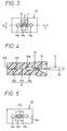
- One end of the fiber fixed hole H is open to a ferrule end face 10b, and the other end thereof is open to a bottom portion of an adhesive agent pool 10h formed on the rear end face, so that an optical fiber is fixed to the ferrule 10 with an adhesive agent after the optical fiber is inserted.
- the fiber fixed holes H are arranged so that the center axis lines 15a and 15b of the fiber fixed holes H and the center axis lines 16a and 16b of the alignment pin holes 10a form a same plane (see FIG. 3).
- the ferrule in accordance with the present invention is molded using the aforesaid synthetic resin in other embodiments described later as well.
- the fiber fixed hole H has a fiber hole 10c, a fiber guide hole 10d, and a fiber insertion hole 10e, these holes having the same hole center, and tapered portions 10f and 10g are provided between the fiber hole 10c and the fiber guide hole 10d and between the fiber guide hole 10d and the fiber insertion hole 10e, respectively.
- the fiber fixed holes H are formed at a predetermined interval. Specifically, as shown in FIG. 3, a wall with a thickness Z is formed between the fiber insertion holes 10e of the fiber fixed holes H. Thereby, each optical fiber can be inserted surely into a predetermined fiber insertion hole. Also, since the fiber insertion holes having a substantially circular shape on the end face are formed separately, the aligning operation at the time of optical fiber insertion is especially excellent.
- the fiber hole 10c is formed so as to have a diameter slightly larger than that of the fiber 5a, which is provided by removing a sheathed portion 5b from an inserted optical ribbon fiber 5 (see FIG. 4), and is open to a ferrule end face 10b.
- the fiber guide hole 10d which has a diameter larger than that of the fiber hole 10c, guides, into the fiber hole 10c, the optical fiber inserted into the fiber insertion hole 10e from the rear part of the ferrule 1.
- the fiber insertion hole 10e which has a diameter larger than that of the fiber guide hole 10d, guides the optical ribbon fiber into the ferrule 10.
- the tapered portion 10f, 10g guides the optical fiber inserted into the fiber insertion hole 10e into the fiber guide hole 10d and the fiber hole 10c smoothly without the optical fiber abutting on the boundary of the connected hole.
- the opening of the adhesive agent pool 10h is formed so that the width (X in FIG. 2(a)) in the direction of arrangement of the fiber insertion holes 10e, that is, in the direction of arrangement of the sheathed portion of the inserted optical ribbon fiber (the direction of P in FIG. 3) is smaller than the width (Y in FIG. 2(a)) in the direction perpendicular to the direction of arrangement of the sheathed portion (the direction of Q in FIG. 3).
- the adhesive agent pool 10h allows an adhesive agent to be easily poured in each fiber fixed hole H, and also prevents the adhesive agent from flowing out of the ferrule 10 along the optical fiber after the optical fiber is inserted.
- the fiber guide hole 10d of the ferrule 10 preferably has a greater length. This is because the presence of adhesive agent in some degree of quantity between the inside face of hole and the inserted fiber 5a (see FIG. 4) contributes to an increase in strength against a pulling-out force.
- the adhesive agent used for the ferrule 10 has a coefficient of linear expansion different from that of the synthetic resin composing the ferrule 10 in the heat cycle test specified in Section 8.2 of JIS C 5961 or in the wet heat test etc. specified in Section 8.4 of JIS C 5961.
- the adhesive agent has characteristics of high hygroscopic property, and easily involves air bubbles. For these reasons, the ferrule 10 easily produces variations in connection loss caused by the temperature variations in the application environment.
- the dimensional conditions of the fiber guide hole 10d should preferably be as described below in order that the condition of the strength against the pulling-out force of 19.6 N is satisfied and the variations in connection loss in the heat cycle test or the wet heat test are not larger than 0.2 dB.
- the diameter of the fiber hole 10c should be set so that the relationship expressed by the following equations holds. ( Df + 0.06 ) ⁇ D ⁇ ( Din ⁇ 0.2 ) Lf ⁇ Lg ⁇ 2 Lf
- a gap between the inside face of the fiber guide hole 10d and the fiber 5a is filled with the adhesive agent.
- this gap is preferably 0.01 mm or more larger than the maximum filler particle diameter.
- the ferrule 10 constructed as described above is assembled into a multi-connector by inserting an optical fiber in a way as described below.
- thermosetting adhesive agent a proper quantity of a thermosetting adhesive agent is supplied from the adhesive agent pool 10h at the rear part of the ferrule 10, and is sucked from the fiber holes 10c that is open to the ferrule end face 10b. Thereby, the adhesive agent is packed in the whole of the fiber fixed holes H, that is, the fiber holes 10c, fiber guide holes 10d, and fiber insertion holes 10e of the ferrule 10.
- the adhesive agent can be poured easily into the fiber fixed holes.
- the optical ribbon fiber 5 in which a sheathed portion 5b of a length corresponding to the length of the fiber hole 10c and fiber guide hole 10d is removed from the tip end side, and a fiber 5a is exposed, is inserted from the fiber insertion hole 10e at the rear part of the ferrule 10. Then, the adhesive agent is cured by heat in a state in which the tip end of the fiber 5a slightly projects from the ferrule end face 10b.
- the end of the sheathed portion 5b comes into contact with the tapered portion 10g between the fiber guide hole 10d and the fiber insertion hole 10e, so that the optical ribbon fiber 5 stops temporarily.
- the quantity of the adhesive agent packed in the fiber guide hole 10d can be made constant. Also, by this operation, the adhesive agent can be intruded between the inside face of the fiber hole 10c and the fiber 5a.
- the ferrule 10 has the fiber fixed hole H into which the optical fiber can be inserted easily without breakage of the optical ribbon fiber 5 and which can provide a sufficient strength for bonding to the optical ribbon fiber 5, and can restrain variations in connection loss caused by the temperature variations.
- the adhesive agent pool 10h is formed, even if a reverse flow of adhesive agent is produced in the fiber fixed hole by the insertion of optical fiber, the adhesive agent caused to flow out of the opening of the fiber insertion hole by this reverse flow stays in the adhesive agent pool 10h, and does not flow unnecessarily out of the ferrule 10.
- the width Y of the adhesive agent pool 10h in the direction perpendicular to the direction of arrangement of sheathed portion is larger than the width X thereof in the direction of arrangement of sheathed portion as described above, a large adhesive agent pool can be formed between the alignment pin holes at a limited interval while the thickness between the alignment pin hole 10a and the adhesive agent pool 10h is maintained sufficiently in terms of strength, so that the above-described outflow from the ferrule 10 can be prevented surely.
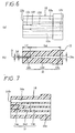
- the fiber insertion hole need not necessarily be formed separately.
- the fiber insertion hole may be formed as a common fiber insertion hole 10p that introduces a plurality of sheathed portions, and convex portions (movement regulating means) 10q may be provided in the fiber insertion hole 10p to regulate the movement of sheathed portion in the direction of arrangement of sheathed portion. Since the convex portions 10q are formed, the optical fiber can be inserted surely in the predetermined fiber insertion hole as in the case where the fiber insertion hole is formed separately.
- a ferrule 12 is provided with two alignment pin holes 12a for inserting alignment pins , and two independent fiber fixed holes H which are formed at a predetermined interval between the two alignment pin holes 12a.
- One end of the fiber fixed hole H is open to a ferrule end face 12b, and the other end thereof is open to the rear end face of ferrule.
- An optical fiber is inserted into and fixed to the fiber fixed hole H with an adhesive agent.
- Each of the fiber fixed holes H has a fiber hole 12c, a fiber guide hole 12d, and a fiber insertion hole 12e, these holes having the same hole center.
- the fiber guide hole 12d is formed so that the diameter thereof decreases gradually from the side of the fiber insertion hole 12e toward the fiber hole 12c, and a tapered portion 12f is provided between the fiber guide hole 12d and the fiber hole 12c.
- the fiber guide hole 12d and the fiber insertion hole 12e are formed into a continuous taper shape.
- the ferrule 12 is formed into a taper shape such that the diameter of the fiber guide hole 12d decreases gradually from the side of the fiber insertion hole 12e toward the fiber hole 12c. It is preferable that the ferrule 12 be formed so that each of the fiber fixed holes H satisfies the same relational equation as that of the fiber fixed hole H of the first embodiment.
- the diameter of the fiber guide hole 12d is an average diameter of (Df + Din)/2 (nm).
- a ferrule in accordance with the present invention may be provided with two alignment pin holes 14a for inserting alignment pins, and two independent fiber fixed holes H which are formed at a predetermined interval between the two alignment pin holes 14a.
- One end of fiber fixed hole H is open to a ferrule end face 14b, the other end thereof is open to the rear end face of ferrule.
- An optical fiber is inserted into and fixed to the fiber fixed hole H with an adhesive agent.
- Each of the fiber fixed hole H has a fiber hole 14c, a fiber guide hole 14d, and a fiber insertion hole 14e, these holes having the same hole center.
- the fiber guide hole 14d is formed so that the diameter thereof decreases gradually from the side of the fiber insertion hole 14e toward the fiber hole 14c.
- the diameter of the fiber guide hole 14d is an average diameter of (Df + Din)/2 (nm).
Landscapes
- Physics & Mathematics (AREA)
- General Physics & Mathematics (AREA)
- Optics & Photonics (AREA)
- Mechanical Coupling Of Light Guides (AREA)
Claims (7)
- Faserhülse, die mit zwei Passstiftlöchern (10a), in die Passstifte zur Positionierung bezüglich einer Gegenfaserhülse eingesetzt werden, und mehreren Faserfixierlöchern (H) versehen ist, die an vorgegebenen Stellen entlang einer Querachse zwischen je zwei Passstiftlöchern (10a) zur Aufnahme einer optischen Faser (5) ausgebildet sind, wobei jedes der Faserfixierlöcher (H) mindestens einen Faserführungslochabschnitt (10d) zur Führung der optischen Faser (5) und einen mit dem Faserführungslochabschnitt (10d) verbundenen Faserlochabschnitt (10c) zur Aufnahme des Spitzenendes der optischen Faser (5), einen mit jedem Faserführungslochabschnitt (10d) verbundenen Fasereinstecklochabschnitt (10e) zur Aufnahme eines ummantelten Abschnitts (5b) der optischen Faser (5) in der Faserhülse (10) aufweist, wobei zwischen jedem Faserführungsloch (10d) und dem Fasereinsteckloch (10e) ein Verbindungsabschnitt (10g) verjüngt ausgebildet ist, wobei mindestens ein Fasereinstecklochabschnitt (10e) einen Napf (10h) zur Aufnahme eines Klebstoffs aufweist, der an seinem hinteren Ende zum Fixieren der optischen Faser (5) ausgebildet ist, dadurch gekennzeichnet, daß
die Breite (Y) des Öffnungsabschnitts des Klebstoffnapfs (10h) in senkrechter Richtung zu der Querachse größer ist als die Breite (X) des Öffnungsabschnitts in Richtung der Querachse. - Faserhülse nach Anspruch 1, wobei ein Fasereinstecklochabschnitt als gemeinsames Fasereinsteckloch (10p) zur Aufnahme von ummantelten Abschnitten (5b) mehrerer Fasern (5) ausgebildet ist.
- Faserhülse nach Anspruch 2, wobei der Fasereinstecklochabschnitt (10p) mit einer Bewegungsreguliereinrichtung (10q) versehen ist, um eine Bewegung der ummantelten Abschnitte (5b) entlang der Querachse zu verhindern.
- Faserhülse nach Anspruch 3, wobei die Bewegungsreguliereinrichtung einen konvexen Abschnitt (10q) aufweist, der sich in das Fasereinsteckloch (10p) erstreckt, und wobei die Breite des Fasereinstecklochs (10p) an dem konvexen Abschnitt (10q) in einer zur Querachse senkrechten Richtung kleiner ist als der Durchmesser eines ummantelten Abschnitts (5b) einer Faser (5).
- Faserhülse nach einem der vorstehenden Ansprüche, wobei der Faserführungslochabschnitt (12d) und der Fasereinstecklochabschnitt (12e) zu einer kontinuierlichen verjüngten Form geformt sind.
- Faserhülse nach einem der vorstehenden Ansprüche, wobei der Faserführungslochabschnitt (12d) so geformt ist, daß sein Durchmesser von der Seite des Fasereinstecklochs (12e) zum Faserloch (12c) hin allmählich abnimmt.
- Verfahren zum Einsetzen einer optischen Faser (5) in eine Faserhülse (10) nach einem der vorstehenden Ansprüche, mit den folgenden Schritten:Zuführen eines Klebstoffs aus dem Klebstoffnapf (10h) in die Faserfixierlöcher (H) durchAnsaugen des Klebstoffs von den Faserlöchem (10c) aus, die an einer Stirnfläche (10b) der Faserhülse (10) offen sind;Einsetzen einer von einem ummantelten Abschnitt (5b) eines Lichtleiterbands (5) freigelegten Faser (5a) in das Faserloch (10c); undAushärten des Klebstoffs.
Priority Applications (3)
| Application Number | Priority Date | Filing Date | Title |
|---|---|---|---|
| DE60117492T DE60117492T2 (de) | 2001-11-15 | 2001-11-15 | Faseroptischer Steckerstift |
| EP01309628A EP1312954B1 (de) | 2001-11-15 | 2001-11-15 | Faseroptischer Steckerstift |
| AT01309628T ATE319113T1 (de) | 2001-11-15 | 2001-11-15 | Faseroptischer steckerstift |
Applications Claiming Priority (1)
| Application Number | Priority Date | Filing Date | Title |
|---|---|---|---|
| EP01309628A EP1312954B1 (de) | 2001-11-15 | 2001-11-15 | Faseroptischer Steckerstift |
Publications (2)
| Publication Number | Publication Date |
|---|---|
| EP1312954A1 EP1312954A1 (de) | 2003-05-21 |
| EP1312954B1 true EP1312954B1 (de) | 2006-03-01 |
Family
ID=8182460
Family Applications (1)
| Application Number | Title | Priority Date | Filing Date |
|---|---|---|---|
| EP01309628A Expired - Lifetime EP1312954B1 (de) | 2001-11-15 | 2001-11-15 | Faseroptischer Steckerstift |
Country Status (3)
| Country | Link |
|---|---|
| EP (1) | EP1312954B1 (de) |
| AT (1) | ATE319113T1 (de) |
| DE (1) | DE60117492T2 (de) |
Cited By (1)
| Publication number | Priority date | Publication date | Assignee | Title |
|---|---|---|---|---|
| WO2025175183A1 (en) * | 2024-02-14 | 2025-08-21 | Us Conec Ltd. | Mass insertion of optical fibers to active area device |
Families Citing this family (4)
| Publication number | Priority date | Publication date | Assignee | Title |
|---|---|---|---|---|
| US7503395B2 (en) | 2005-05-21 | 2009-03-17 | Schlumberger Technology Corporation | Downhole connection system |
| JP7070156B2 (ja) * | 2018-06-28 | 2022-05-18 | 日本電信電話株式会社 | 光部品およびその製造方法 |
| US11927812B2 (en) * | 2019-02-25 | 2024-03-12 | Sumitomo Electric Industries, Ltd. | Ferrule and optical connector |
| JP7724941B1 (ja) * | 2024-12-27 | 2025-08-18 | 株式会社フジクラ | 光コネクタ、および光接続構造 |
Family Cites Families (4)
| Publication number | Priority date | Publication date | Assignee | Title |
|---|---|---|---|---|
| CH687105A5 (de) * | 1994-10-07 | 1996-09-13 | Eidgenoess Tech Hochschule | Optischer Mehrfachstecker. |
| JPH09203825A (ja) * | 1996-01-24 | 1997-08-05 | Furukawa Electric Co Ltd:The | 多心光コネクタ |
| JP3005754B2 (ja) * | 1996-10-03 | 2000-02-07 | 東京特殊電線株式会社 | 光コネクタ用2心フェルール構造 |
| JP3869130B2 (ja) * | 1998-10-01 | 2007-01-17 | 古河電気工業株式会社 | 多心光コネクタ及びその組立方法 |
-
2001
- 2001-11-15 AT AT01309628T patent/ATE319113T1/de not_active IP Right Cessation
- 2001-11-15 DE DE60117492T patent/DE60117492T2/de not_active Expired - Lifetime
- 2001-11-15 EP EP01309628A patent/EP1312954B1/de not_active Expired - Lifetime
Cited By (1)
| Publication number | Priority date | Publication date | Assignee | Title |
|---|---|---|---|---|
| WO2025175183A1 (en) * | 2024-02-14 | 2025-08-21 | Us Conec Ltd. | Mass insertion of optical fibers to active area device |
Also Published As
| Publication number | Publication date |
|---|---|
| DE60117492T2 (de) | 2006-10-19 |
| DE60117492D1 (de) | 2006-04-27 |
| EP1312954A1 (de) | 2003-05-21 |
| ATE319113T1 (de) | 2006-03-15 |
Similar Documents
| Publication | Publication Date | Title |
|---|---|---|
| US7121733B2 (en) | Ferrule | |
| US6062740A (en) | Optical connector and method of making the same | |
| EP0490698B1 (de) | Verfahren zum Anreihen von Faserendhülsen eines anreihbaren optischen Steckers und optischer Anreihstecker | |
| US7512307B2 (en) | Method of making optical connector ferrule, die for making optical connector ferrule, optical connector ferrule made by this method, and optical connector and optical wiring system using the same | |
| EP0444347B1 (de) | Montagemethode eines eine Vielzahl von V-Nuten auf einer Si-Scheibe enthaltenden faseroptischen Steckers | |
| CA2278067C (en) | Fiber optic connector sleeve having positioning ribs | |
| KR20010042026A (ko) | 대량 병렬 광 상호접속 시스템 | |
| US6634800B2 (en) | Ferrule for optical connector | |
| KR19990014240A (ko) | 광섬유 커넥터 페룰을 조립하기 위한 고정구 | |
| US6210047B1 (en) | Method of fabricating a fiber optic connector ferrule | |
| KR100452579B1 (ko) | 다중 광섬유 커넥터 및 소켓 시스템과 대량 병렬 광학 커넥터 | |
| JP7828489B2 (ja) | フェルール、光コネクタおよび光コネクタの製造方法 | |
| KR100323007B1 (ko) | 광섬유커넥터페룰 | |
| EP1312954B1 (de) | Faseroptischer Steckerstift | |
| KR100289477B1 (ko) | 광섬유 케이블용 커넥터 페룰 내의 정렬 시스템 | |
| US6264375B1 (en) | Fiber optic connector ferrule and method of making the same | |
| JP3869130B2 (ja) | 多心光コネクタ及びその組立方法 | |
| US6210045B1 (en) | Alignment sleeve for aligning ferrules and associated assembly method | |
| JP2009193030A (ja) | 光ファイバ付き光フェルール | |
| US7513694B2 (en) | Component for connecting optical fibers, optical fiber connection structure, and optical fiber connecting method | |
| JP2001324650A (ja) | フェルール | |
| JP2009151338A (ja) | フェルール | |
| JP4802308B2 (ja) | 光コネクタ用フェルール、光コネクタおよび光コネクタの製造方法 | |
| JP2001066466A (ja) | 光コネクタ | |
| US20020157774A1 (en) | Ferrule manufacture method and ferrule |
Legal Events
| Date | Code | Title | Description |
|---|---|---|---|
| PUAI | Public reference made under article 153(3) epc to a published international application that has entered the european phase |
Free format text: ORIGINAL CODE: 0009012 |
|
| AK | Designated contracting states |
Designated state(s): AT BE CH CY DE DK ES FI FR GB GR IE IT LI LU MC NL PT SE TR |
|
| AX | Request for extension of the european patent |
Extension state: AL LT LV MK RO SI |
|
| AKX | Designation fees paid | ||
| 17P | Request for examination filed |
Effective date: 20031120 |
|
| RBV | Designated contracting states (corrected) |
Designated state(s): AT BE CH CY DE DK ES FI FR GB GR IE IT LI LU MC NL PT SE TR |
|
| REG | Reference to a national code |
Ref country code: DE Ref legal event code: 8566 |
|
| RIN1 | Information on inventor provided before grant (corrected) |
Inventor name: YAMADA, HIROYUKI, THE FURUKAWA ELECTRIC CO. LTD Inventor name: VERMEULEN, WILFRED Inventor name: GEFFEN, SJOERD VAN Inventor name: HENGELMOLEN, ARIE Inventor name: KAMIKO, MICHIYASU Inventor name: BAKEL, RENE VAN Inventor name: ARTS, KO Inventor name: GURRERI, MIKE Inventor name: SCHOLTEN, MARTIJN Inventor name: HIRAO, MASAHIRO, THE FURUKAWA ELECTRIC CO. LTD Inventor name: ELOISE, SHURBY |
|
| 17Q | First examination report despatched |
Effective date: 20041115 |
|
| GRAP | Despatch of communication of intention to grant a patent |
Free format text: ORIGINAL CODE: EPIDOSNIGR1 |
|
| GRAS | Grant fee paid |
Free format text: ORIGINAL CODE: EPIDOSNIGR3 |
|
| GRAA | (expected) grant |
Free format text: ORIGINAL CODE: 0009210 |
|
| AK | Designated contracting states |
Kind code of ref document: B1 Designated state(s): AT BE CH CY DE DK ES FI FR GB GR IE IT LI LU MC NL PT SE TR |
|
| PG25 | Lapsed in a contracting state [announced via postgrant information from national office to epo] |
Ref country code: IT Free format text: LAPSE BECAUSE OF FAILURE TO SUBMIT A TRANSLATION OF THE DESCRIPTION OR TO PAY THE FEE WITHIN THE PRESCRIBED TIME-LIMIT;WARNING: LAPSES OF ITALIAN PATENTS WITH EFFECTIVE DATE BEFORE 2007 MAY HAVE OCCURRED AT ANY TIME BEFORE 2007. THE CORRECT EFFECTIVE DATE MAY BE DIFFERENT FROM THE ONE RECORDED. Effective date: 20060301 Ref country code: AT Free format text: LAPSE BECAUSE OF FAILURE TO SUBMIT A TRANSLATION OF THE DESCRIPTION OR TO PAY THE FEE WITHIN THE PRESCRIBED TIME-LIMIT Effective date: 20060301 Ref country code: LI Free format text: LAPSE BECAUSE OF FAILURE TO SUBMIT A TRANSLATION OF THE DESCRIPTION OR TO PAY THE FEE WITHIN THE PRESCRIBED TIME-LIMIT Effective date: 20060301 Ref country code: NL Free format text: LAPSE BECAUSE OF FAILURE TO SUBMIT A TRANSLATION OF THE DESCRIPTION OR TO PAY THE FEE WITHIN THE PRESCRIBED TIME-LIMIT Effective date: 20060301 Ref country code: BE Free format text: LAPSE BECAUSE OF FAILURE TO SUBMIT A TRANSLATION OF THE DESCRIPTION OR TO PAY THE FEE WITHIN THE PRESCRIBED TIME-LIMIT Effective date: 20060301 Ref country code: FI Free format text: LAPSE BECAUSE OF FAILURE TO SUBMIT A TRANSLATION OF THE DESCRIPTION OR TO PAY THE FEE WITHIN THE PRESCRIBED TIME-LIMIT Effective date: 20060301 Ref country code: CH Free format text: LAPSE BECAUSE OF FAILURE TO SUBMIT A TRANSLATION OF THE DESCRIPTION OR TO PAY THE FEE WITHIN THE PRESCRIBED TIME-LIMIT Effective date: 20060301 |
|
| REG | Reference to a national code |
Ref country code: GB Ref legal event code: FG4D |
|
| REG | Reference to a national code |
Ref country code: CH Ref legal event code: EP |
|
| REG | Reference to a national code |
Ref country code: IE Ref legal event code: FG4D |
|
| REF | Corresponds to: |
Ref document number: 60117492 Country of ref document: DE Date of ref document: 20060427 Kind code of ref document: P |
|
| PG25 | Lapsed in a contracting state [announced via postgrant information from national office to epo] |
Ref country code: SE Free format text: LAPSE BECAUSE OF FAILURE TO SUBMIT A TRANSLATION OF THE DESCRIPTION OR TO PAY THE FEE WITHIN THE PRESCRIBED TIME-LIMIT Effective date: 20060601 Ref country code: DK Free format text: LAPSE BECAUSE OF FAILURE TO SUBMIT A TRANSLATION OF THE DESCRIPTION OR TO PAY THE FEE WITHIN THE PRESCRIBED TIME-LIMIT Effective date: 20060601 |
|
| PG25 | Lapsed in a contracting state [announced via postgrant information from national office to epo] |
Ref country code: ES Free format text: LAPSE BECAUSE OF FAILURE TO SUBMIT A TRANSLATION OF THE DESCRIPTION OR TO PAY THE FEE WITHIN THE PRESCRIBED TIME-LIMIT Effective date: 20060612 |
|
| PG25 | Lapsed in a contracting state [announced via postgrant information from national office to epo] |
Ref country code: PT Free format text: LAPSE BECAUSE OF FAILURE TO SUBMIT A TRANSLATION OF THE DESCRIPTION OR TO PAY THE FEE WITHIN THE PRESCRIBED TIME-LIMIT Effective date: 20060801 |
|
| NLV1 | Nl: lapsed or annulled due to failure to fulfill the requirements of art. 29p and 29m of the patents act | ||
| REG | Reference to a national code |
Ref country code: CH Ref legal event code: PL |
|
| ET | Fr: translation filed | ||
| PG25 | Lapsed in a contracting state [announced via postgrant information from national office to epo] |
Ref country code: IE Free format text: LAPSE BECAUSE OF NON-PAYMENT OF DUE FEES Effective date: 20061115 |
|
| PG25 | Lapsed in a contracting state [announced via postgrant information from national office to epo] |
Ref country code: MC Free format text: LAPSE BECAUSE OF NON-PAYMENT OF DUE FEES Effective date: 20061130 |
|
| PGFP | Annual fee paid to national office [announced via postgrant information from national office to epo] |
Ref country code: IT Payment date: 20061130 Year of fee payment: 6 |
|
| PLBE | No opposition filed within time limit |
Free format text: ORIGINAL CODE: 0009261 |
|
| STAA | Information on the status of an ep patent application or granted ep patent |
Free format text: STATUS: NO OPPOSITION FILED WITHIN TIME LIMIT |
|
| 26N | No opposition filed |
Effective date: 20061204 |
|
| PG25 | Lapsed in a contracting state [announced via postgrant information from national office to epo] |
Ref country code: GR Free format text: LAPSE BECAUSE OF FAILURE TO SUBMIT A TRANSLATION OF THE DESCRIPTION OR TO PAY THE FEE WITHIN THE PRESCRIBED TIME-LIMIT Effective date: 20060602 |
|
| PG25 | Lapsed in a contracting state [announced via postgrant information from national office to epo] |
Ref country code: TR Free format text: LAPSE BECAUSE OF FAILURE TO SUBMIT A TRANSLATION OF THE DESCRIPTION OR TO PAY THE FEE WITHIN THE PRESCRIBED TIME-LIMIT Effective date: 20060301 Ref country code: LU Free format text: LAPSE BECAUSE OF NON-PAYMENT OF DUE FEES Effective date: 20061115 |
|
| PG25 | Lapsed in a contracting state [announced via postgrant information from national office to epo] |
Ref country code: CY Free format text: LAPSE BECAUSE OF FAILURE TO SUBMIT A TRANSLATION OF THE DESCRIPTION OR TO PAY THE FEE WITHIN THE PRESCRIBED TIME-LIMIT Effective date: 20060301 |
|
| PG25 | Lapsed in a contracting state [announced via postgrant information from national office to epo] |
Ref country code: IT Free format text: LAPSE BECAUSE OF NON-PAYMENT OF DUE FEES Effective date: 20071115 |
|
| REG | Reference to a national code |
Ref country code: FR Ref legal event code: PLFP Year of fee payment: 15 |
|
| REG | Reference to a national code |
Ref country code: FR Ref legal event code: PLFP Year of fee payment: 16 |
|
| REG | Reference to a national code |
Ref country code: FR Ref legal event code: PLFP Year of fee payment: 17 |
|
| REG | Reference to a national code |
Ref country code: FR Ref legal event code: PLFP Year of fee payment: 18 |
|
| REG | Reference to a national code |
Ref country code: DE Ref legal event code: R081 Ref document number: 60117492 Country of ref document: DE Owner name: TE CONNECTIVITY CORPORATION, BERWYN, US Free format text: FORMER OWNERS: THE FURUKAWA ELECTRIC CO., LTD., TOKIO/TOKYO, JP; TYCO ELECTRONICS CORP., MIDDLETOWN, PA., US Ref country code: DE Ref legal event code: R081 Ref document number: 60117492 Country of ref document: DE Owner name: THE FURUKAWA ELECTRIC CO., LTD., JP Free format text: FORMER OWNERS: THE FURUKAWA ELECTRIC CO., LTD., TOKIO/TOKYO, JP; TYCO ELECTRONICS CORP., MIDDLETOWN, PA., US |
|
| PGFP | Annual fee paid to national office [announced via postgrant information from national office to epo] |
Ref country code: GB Payment date: 20201104 Year of fee payment: 20 Ref country code: DE Payment date: 20201103 Year of fee payment: 20 Ref country code: FR Payment date: 20201013 Year of fee payment: 20 |
|
| REG | Reference to a national code |
Ref country code: DE Ref legal event code: R071 Ref document number: 60117492 Country of ref document: DE |
|
| REG | Reference to a national code |
Ref country code: GB Ref legal event code: PE20 Expiry date: 20211114 |
|
| PG25 | Lapsed in a contracting state [announced via postgrant information from national office to epo] |
Ref country code: GB Free format text: LAPSE BECAUSE OF EXPIRATION OF PROTECTION Effective date: 20211114 |