EP1312962A2 - Erdelektrodeneinheit für eine elektrische Vorrichtung unter Wasser - Google Patents
Erdelektrodeneinheit für eine elektrische Vorrichtung unter Wasser Download PDFInfo
- Publication number
- EP1312962A2 EP1312962A2 EP02292598A EP02292598A EP1312962A2 EP 1312962 A2 EP1312962 A2 EP 1312962A2 EP 02292598 A EP02292598 A EP 02292598A EP 02292598 A EP02292598 A EP 02292598A EP 1312962 A2 EP1312962 A2 EP 1312962A2
- Authority
- EP
- European Patent Office
- Prior art keywords
- cable
- electrode
- earthing
- electrode assembly
- assembly according
- Prior art date
- Legal status (The legal status is an assumption and is not a legal conclusion. Google has not performed a legal analysis and makes no representation as to the accuracy of the status listed.)
- Withdrawn
Links
- 230000000694 effects Effects 0.000 claims abstract description 13
- 238000009434 installation Methods 0.000 claims abstract description 13
- 238000000034 method Methods 0.000 claims abstract description 8
- UFHFLCQGNIYNRP-UHFFFAOYSA-N Hydrogen Chemical compound [H][H] UFHFLCQGNIYNRP-UHFFFAOYSA-N 0.000 claims description 46
- 239000001257 hydrogen Substances 0.000 claims description 39
- 229910052739 hydrogen Inorganic materials 0.000 claims description 39
- 230000004888 barrier function Effects 0.000 claims description 27
- BASFCYQUMIYNBI-UHFFFAOYSA-N platinum Chemical compound [Pt] BASFCYQUMIYNBI-UHFFFAOYSA-N 0.000 claims description 10
- RTAQQCXQSZGOHL-UHFFFAOYSA-N Titanium Chemical group [Ti] RTAQQCXQSZGOHL-UHFFFAOYSA-N 0.000 claims description 8
- 229910052741 iridium Inorganic materials 0.000 claims description 5
- GKOZUEZYRPOHIO-UHFFFAOYSA-N iridium atom Chemical compound [Ir] GKOZUEZYRPOHIO-UHFFFAOYSA-N 0.000 claims description 5
- 229910003455 mixed metal oxide Inorganic materials 0.000 claims description 5
- 229910052697 platinum Inorganic materials 0.000 claims description 5
- 229910052715 tantalum Inorganic materials 0.000 claims description 5
- GUVRBAGPIYLISA-UHFFFAOYSA-N tantalum atom Chemical compound [Ta] GUVRBAGPIYLISA-UHFFFAOYSA-N 0.000 claims description 5
- 239000011248 coating agent Substances 0.000 claims description 4
- 238000000576 coating method Methods 0.000 claims description 4
- 239000010410 layer Substances 0.000 description 43
- XLYOFNOQVPJJNP-UHFFFAOYSA-N water Substances O XLYOFNOQVPJJNP-UHFFFAOYSA-N 0.000 description 15
- 239000000835 fiber Substances 0.000 description 10
- 230000003287 optical effect Effects 0.000 description 9
- 229910000831 Steel Inorganic materials 0.000 description 8
- 239000010949 copper Substances 0.000 description 8
- 229910052802 copper Inorganic materials 0.000 description 8
- 230000007797 corrosion Effects 0.000 description 8
- 238000005260 corrosion Methods 0.000 description 8
- 239000010959 steel Substances 0.000 description 8
- RYGMFSIKBFXOCR-UHFFFAOYSA-N Copper Chemical compound [Cu] RYGMFSIKBFXOCR-UHFFFAOYSA-N 0.000 description 7
- 239000000463 material Substances 0.000 description 7
- 239000004698 Polyethylene Substances 0.000 description 5
- 238000004891 communication Methods 0.000 description 5
- 230000035515 penetration Effects 0.000 description 5
- -1 polyethylene Polymers 0.000 description 5
- 229920000573 polyethylene Polymers 0.000 description 5
- 239000004020 conductor Substances 0.000 description 4
- 229910052751 metal Inorganic materials 0.000 description 4
- 239000002184 metal Substances 0.000 description 4
- 230000009471 action Effects 0.000 description 3
- 238000013459 approach Methods 0.000 description 3
- 238000013461 design Methods 0.000 description 3
- 230000008569 process Effects 0.000 description 3
- 230000008439 repair process Effects 0.000 description 3
- 102000016904 Armadillo Domain Proteins Human genes 0.000 description 2
- 108010014223 Armadillo Domain Proteins Proteins 0.000 description 2
- 241000289632 Dasypodidae Species 0.000 description 2
- 238000010438 heat treatment Methods 0.000 description 2
- 238000011084 recovery Methods 0.000 description 2
- 239000013535 sea water Substances 0.000 description 2
- 239000003643 water by type Substances 0.000 description 2
- ATJFFYVFTNAWJD-UHFFFAOYSA-N Tin Chemical compound [Sn] ATJFFYVFTNAWJD-UHFFFAOYSA-N 0.000 description 1
- GWEVSGVZZGPLCZ-UHFFFAOYSA-N Titan oxide Chemical compound O=[Ti]=O GWEVSGVZZGPLCZ-UHFFFAOYSA-N 0.000 description 1
- 239000004411 aluminium Substances 0.000 description 1
- 229910052782 aluminium Inorganic materials 0.000 description 1
- XAGFODPZIPBFFR-UHFFFAOYSA-N aluminium Chemical compound [Al] XAGFODPZIPBFFR-UHFFFAOYSA-N 0.000 description 1
- 238000005452 bending Methods 0.000 description 1
- 230000008859 change Effects 0.000 description 1
- 150000001879 copper Chemical class 0.000 description 1
- 230000007547 defect Effects 0.000 description 1
- 230000002950 deficient Effects 0.000 description 1
- 238000010292 electrical insulation Methods 0.000 description 1
- 239000007772 electrode material Substances 0.000 description 1
- 238000005868 electrolysis reaction Methods 0.000 description 1
- 230000003628 erosive effect Effects 0.000 description 1
- 239000012530 fluid Substances 0.000 description 1
- 239000013505 freshwater Substances 0.000 description 1
- 239000007789 gas Substances 0.000 description 1
- 239000000383 hazardous chemical Substances 0.000 description 1
- 150000002431 hydrogen Chemical class 0.000 description 1
- 239000011810 insulating material Substances 0.000 description 1
- 230000013011 mating Effects 0.000 description 1
- 238000012986 modification Methods 0.000 description 1
- 230000004048 modification Effects 0.000 description 1
- 230000000149 penetrating effect Effects 0.000 description 1
- 229920003023 plastic Polymers 0.000 description 1
- 239000004033 plastic Substances 0.000 description 1
- 229920001084 poly(chloroprene) Polymers 0.000 description 1
- 230000000750 progressive effect Effects 0.000 description 1
- 239000011253 protective coating Substances 0.000 description 1
- 230000001681 protective effect Effects 0.000 description 1
- 239000011241 protective layer Substances 0.000 description 1
- 239000011347 resin Substances 0.000 description 1
- 229920002994 synthetic fiber Polymers 0.000 description 1
- 229920003002 synthetic resin Polymers 0.000 description 1
- 239000011135 tin Substances 0.000 description 1
- 229910052718 tin Inorganic materials 0.000 description 1
- 239000010936 titanium Substances 0.000 description 1
- 229910052719 titanium Inorganic materials 0.000 description 1
- OGIDPMRJRNCKJF-UHFFFAOYSA-N titanium oxide Inorganic materials [Ti]=O OGIDPMRJRNCKJF-UHFFFAOYSA-N 0.000 description 1
- 238000012546 transfer Methods 0.000 description 1
Images

Classifications
-
- G—PHYSICS
- G02—OPTICS
- G02B—OPTICAL ELEMENTS, SYSTEMS OR APPARATUS
- G02B6/00—Light guides; Structural details of arrangements comprising light guides and other optical elements, e.g. couplings
- G02B6/44—Mechanical structures for providing tensile strength and external protection for fibres, e.g. optical transmission cables
- G02B6/4401—Optical cables
- G02B6/4415—Cables for special applications
- G02B6/4427—Pressure resistant cables, e.g. undersea cables
- G02B6/4428—Penetrator systems in pressure-resistant devices
-
- G—PHYSICS
- G02—OPTICS
- G02B—OPTICAL ELEMENTS, SYSTEMS OR APPARATUS
- G02B6/00—Light guides; Structural details of arrangements comprising light guides and other optical elements, e.g. couplings
- G02B6/44—Mechanical structures for providing tensile strength and external protection for fibres, e.g. optical transmission cables
- G02B6/4439—Auxiliary devices
- G02B6/4471—Terminating devices ; Cable clamps
- G02B6/44775—Cable seals e.g. feed-through
-
- H—ELECTRICITY
- H02—GENERATION; CONVERSION OR DISTRIBUTION OF ELECTRIC POWER
- H02G—INSTALLATION OF ELECTRIC CABLES OR LINES, OR OF COMBINED OPTICAL AND ELECTRIC CABLES OR LINES
- H02G15/00—Cable fittings
- H02G15/08—Cable junctions
- H02G15/10—Cable junctions protected by boxes, e.g. by distribution, connection or junction boxes
- H02G15/12—Cable junctions protected by boxes, e.g. by distribution, connection or junction boxes for incorporating transformers, loading coils or amplifiers
- H02G15/14—Cable junctions protected by boxes, e.g. by distribution, connection or junction boxes for incorporating transformers, loading coils or amplifiers specially adapted for submarine cables
-
- G—PHYSICS
- G02—OPTICS
- G02B—OPTICAL ELEMENTS, SYSTEMS OR APPARATUS
- G02B6/00—Light guides; Structural details of arrangements comprising light guides and other optical elements, e.g. couplings
- G02B6/44—Mechanical structures for providing tensile strength and external protection for fibres, e.g. optical transmission cables
- G02B6/4401—Optical cables
- G02B6/4429—Means specially adapted for strengthening or protecting the cables
- G02B6/44382—Means specially adapted for strengthening or protecting the cables the means comprising hydrogen absorbing materials
-
- Y—GENERAL TAGGING OF NEW TECHNOLOGICAL DEVELOPMENTS; GENERAL TAGGING OF CROSS-SECTIONAL TECHNOLOGIES SPANNING OVER SEVERAL SECTIONS OF THE IPC; TECHNICAL SUBJECTS COVERED BY FORMER USPC CROSS-REFERENCE ART COLLECTIONS [XRACs] AND DIGESTS
- Y10—TECHNICAL SUBJECTS COVERED BY FORMER USPC
- Y10T—TECHNICAL SUBJECTS COVERED BY FORMER US CLASSIFICATION
- Y10T29/00—Metal working
- Y10T29/49—Method of mechanical manufacture
- Y10T29/49002—Electrical device making
Definitions
- the present invention relates to the field of submerged apparatus, in particular submerged cable systems as used for example in under sea communications involving the transfer of data through fibre optic cables located at the bottom of the sea.
- the cables referred to normally lie either on the sea bed, as is typically the case for deep water installations or they may be buried, beneath the sea bed, either by a natural process or by deliberate action, which may be a method typically employed in shallow water installations. For example, when a cable passes from deep water to a land base, as the shore is approached the cables may be buried beneath the sea bed and continue to be buried under ground when on land to protect them from mechanical damage, interference and such like.
- the invention not only applies to undersea applications, involving for example fibre optic carrying cables, but also applies to any underwater cable installation where an earth is required, including installations in lakes and such like.
- Mechanical protection in the first instance typically involves the use of an insulated polyethylene sheath casing around a core where the various fibres power conductors are situated. However this may be supplemented by one or more layers of steel armouring wires, which is itself protected from the environment, for example from sea water, by an outer sheath or layer of tar or such like.
- One of the protective measures employed in submerged cables which carry in their core optical fibres and power conductors is the use of a metallic layer, typically copper and which is located between the core of the cable and the polyethylene sheath.
- This metallic layer which surrounds optical fibres in the core of the cable, serves the function, amongst other things, of providing a hydrogen barrier. Provided the metallic layer remains intact, it will prevent hydrogen from penetrating to the core of the cable, where it could damage optical fibres typically noticeable in the form of increasing optical losses.
- BU's branching units
- earth for example to discharge into the water the DC powering current from one cable where three cables are joined together.
- a line current of 1-2 amps from one of the three legs of the junction would typically need to flow to earth via the sea. This produces major local electrochemical effects in terms of hydrogen generation and/or metal corrosion from which the system needs to be protected.
- One solution currently employed for providing an earth at a branching unit is to insulate the system earth from the main housing of the branching unit and to connect it directly to a separate electrode, typically made of copper or steel which is placed in the water, either on or in the vicinity of the branching unit.
- any metallic parts within less than about 1 metre from an electrode operated as a cathode in an undersea application may be subject to generally unacceptably high levels of corrosion due to earth currents flowing preferentially into them.
- a further drawback of this solution is that the electrode, which is installed on or near the cable housing, can give rise to handling problems in the cable factory and in marine situations, such as manoeuvring the cable off a drum, cable laying and such like.
- an alternative approach has sometimes been adopted. In this approach, the earth connection is made directly to the metallic BU housing and this housing is in turn electrically connected to the steel armouring wires on one or more of the three cable 'legs'. With this method, all metallic parts are at the same potential so that no corrosion occurs due to earth-return currents.
- the BU housing is coated with an insulating material, whereas the armouring wires are in close contact with the sea, so that the BU earth current flows to sea through the armouring wires, with no build-up of hydrogen near any critical parts.
- This system works very well in shallow water, where the armouring wires are many kilometres long so that the hydrogen produced is distributed over a large area and so there is no build-up sufficient to have any significant effect on critical areas.
- special lengths ( ⁇ 50m) of armouring need to be applied to the cable specifically for this purpose.
- the armour wires need to be terminated at least 2m from the BU and jointing boxes to avoid the hydrogen build-up problems mentioned earlier.
- Such an earth design should operate indefinitely when used as a cathode, and can be used as an anode for a time of the order of one year before corrosion of the armouring wires or other metallic parts becomes unacceptable.
- the aim of the invention is preferably to provide a simple and robust earth electrode assembly usable with different types and sizes of cable as well as in both shallow and deep water applications, which is suitable for providing an earth for a submerged electrical apparatus, e.g. installed in a fibre optic cable communication system such as a branching unit, with an earth, and which can easily be handled in marine situations, such as cable laying.
- a further aim of the invention is preferably to provide an electrode assembly which consistently keeps the electrode in the same position relative to the submerged electrical apparatus after installation of the cable.
- a yet further aim of the invention is preferably to provide an electrode assembly which is capable of operating as either a cathode or as an anode without damaging the system it is earthing, due to the effects of molecular hydrogen and/or corrosion.
- an earthing electrode assembly for providing a submerged electrical apparatus with an earth path, whereby the electrode assembly is provided with an earthing electrode and attachment means so that the electrode assembly is capable of attachment to a cable, while at the same time being electrically insulated from this cable, and the electrode assembly is provided with an insulated electrical connection for connecting it to the submerged electrical apparatus, said connection being of sufficient length to enable the electrode to be located at a distance from the apparatus which is sufficient for the apparatus to be substantially protected from the electrochemical effects resulting from the operation of the electrode.
- a cable system which includes a cable connected to an electrical device to be earthed, the cable system including an earthing electrode, attachment means attaching the electrode to the cable and an insulated electrical connection between the electrode and the electrical apparatus to be earthed, the electrode being located at a distance from the apparatus which is sufficient for the apparatus to be substantially protected from the electrochemical effects resulting from the operation of the electrode.
- a method of installation of an earth electrode on a cable including the steps of: (1) one or more outer layers of the cable, which include cable outer sheath and/or armouring wires, are temporarily cut and displaced so as to expose an inner layer (2) a hydrogen barrier layer is then applied to said exposed inner layer (3) an outer layer is then replaced around the hydrogen barrier layer and sealed by the application of a further electrically insulating cable sheath, and the earth electrode is then attached to the outside of the insulated cable.
- an earthing electrode suitable for providing a submerged earth, whereby the electrode includes a titanium core which is coated with platinum or a mixed metal oxide of tantalum and iridium.
- the attachment means may be arranged so as to attach the electrode releasably to the outside of a cable, using any mechanical attachment means, e.g. a clamping arrangement and such like.
- the electrode is made up of two parts or members, which may for example be of substantially the same size and shape, and which together provide the attachment means and which grip the outer surface of the cable. It is nevertheless entirely feasible to achieve the aims of the invention with three or more such members which together grip the outer surface of the cable. It may also be that the electrode comprises two members which together provide the attachment means and which essentially sandwich the cable by the use of means which urge the two parts of the electrode towards each other, for example by the use of bolts on one member which pass through poles in the other member, on the back of which nuts are located, which when tightened, urge the two members towards each other.
- the two or more members of the electrode are intended to abut one another, to form a substantially cylindrical outer shape, yet at the same time provide a central aperture in which the cable, on which the electrode is being installed, can be located.
- each of the members may be provided with corresponding abutment surfaces, which may for example be flat, one or more of which may furthermore be substantially in the same plane as the axis of the cylindrical outer shape. It may also be that the inside surfaces of this aperture provide the attachment means by gripping the outer surface of the cable.
- the purpose of the attachment means and therefore this gripping action as well as the gripping action of the electrode of embodiments described earlier, is that the electrode is held in place such that it cannot slide along the cable, for example when being manoeuvred into position from off the back of a ship.
- the electrode may include a titanium core which is coated with a mixed metal oxide of tantalum and iridium. It has been found that this combination of materials results in an electrode which is particularly resistant to electrolytic corrosion, which is a particular problem when the electrode is operated as an anode. It has furthermore been found that when an electrode made of these materials is damaged in such a way as to break the coating and expose the titanium core, then during further operation of the electrode, the exposed titanium oxidises giving rise to a further protective coating of titanium oxide over the damaged area. In this way, even when the outer coating of the electrode is damaged, the electrode will in effect repair itself and a good life expectancy for the electrode would still be achievable.
- a good life expectancy of the electrode can also be achieved by the use of a platinum coating on the outside of the electrode.
- the earthing electrode is permanently attached to the cable, the electrode or elements of the electrode having been embedded in one or more layers of the cable, in particular of the outer casing of the cable.
- the electrode may not protrude above the level of the outer surface of the surrounding cable any more than would the casing of a cable-to-cable joint.
- an additional hydrogen barrier layer in the form of a generally coaxial metallic layer which passes between the earthing electrode and the centre of the cable and which extends a predetermined distance on either side of the position of the electrode.
- the additional hydrogen barrier layer can be realised by the use of metallic or metalised tapes which may include a suitable backing material made of plastic, neoprene or such like, however this is not essential.
- the additional hydrogen barrier layer may take the form of a metalised heat shrink layer which is subjected to heating in order for it to shrink onto and thereby seal one or more inner layers of the cable during a heat application process.
- the insulated electrical connection, between the electrode and the apparatus to be earthed is in the form of a separate insulated lead which runs alongside the cable.
- an insulated lead is not essential and any suitable insulated conductor between the electrode and the apparatus to be earthed is envisaged.
- the equipment earth in the branching unit is connected to an insulated electrical lead which passes directly out of the branching unit housing through a sealed opening (5) between the interior of the branching unit housing and the sea, without making electrical contact with the housing.
- This insulated electrical connection in the form of an insulated conducting lead (3) then passes alongside the cable (4a) until the point at which it connects to the earthing electrode (1).
- the earthing electrode generally consists of two mating halves having, when abutted together, a cylindrical outer shape, whereby one of the halves is connected to the insulated connection lead (3) and is electrically connected to the other half by virtue of the contact of the two halves due to their abutting relationship when in the final installed position.
- the abutment surfaces of the two halves are substantially flat and in the same plane as the axis of the cylindrical outer shape.
- bend limiters (2a, 2b) are provided on either side of the earthing electrode.
- the purpose of these is to reduce stresses in the cable which might otherwise be caused by the attachment of the rigid electrode, in a similar manner to the use of bend limiters (7) in relation to the cable attachment of a branching unit (8).
- These bend limiters may furthermore be attached in such a way as to serve the function of locking the earthing electrode in its position so that it does not slide along the cable when the cable is manipulated.
- the earthing electrode does not need to be designed to fit the cable exactly and may therefore include a generous central aperture through which the cable passes, which in turn makes it possible to have one electrode size for a plurality of different cable sizes.
- the earthing electrode in particular the two halves of the earthing electrode preferably include a titanium core which is coated with a mixed metal oxide of tantalum and iridium, however a titanium core which is coated with a platinum layer is also envisaged. It has been found that the choice of these particular materials gives the electrode very good endurance properties, however the earthing electrode of the earthing electrode and cable assembly of the invention can be made from any suitable electrode material, including copper or steel.
- the earthing electrode is preferably located on the cable at a suitable distance from the branching unit, so that molecular hydrogen generated from the electrode when it is operated as a cathode, does not penetrate the branching unit (8) or its associated equipment (6, 7) or is substantially prevented from doing so. Additionally, it needs to be separated from the branching unit (8) and its associated equipment, by a certain distance due to the corrosive effects on any metal work in the vicinity of stray currents emanating from an electrode when being operated as an anode or cathode.
- a distance between electrode and any other equipment of the type mentioned, of at least 5 metres achieves the aims of the invention in that the equipment which is being provided with an earth path can be expected to have a normal life expectancy, of at least 25 years.
- the invention is not limited to a minimum distance of 5 metres and a shorter distance may be acceptable where small currents need to be earthed, sea conditions permit or a shorter life expectancy can be tolerated. Similarly a shorter distance may be acceptable in other circumstances, for example if the cable is installed in a fresh water lake.
- the distance between the electrode and the apparatus to be earthed and therefore the length of the insulated conducting lead (3) will therefore be determined by routine field trials or by calculation and depend on factors such as the shape and size of the electrode, the earthing current, the water properties, the location of the cable, in particular whether it is to be buried beneath the sea bed or not, the type of cable being attached to and the system life expectancy being aimed for.
- the use of the expression "for the apparatus to be protected" in the context of this invention is not therefore an expression of absolute protection, but rather an acceptable degree of protection to achieve the desired system life expectancy.
- the earthing electrode when it is attached to the cable, does not occupy any more space in terms of an increase in the cross sectional area of the cable or an increase in the length of a rigid portion of the cable, than would a normal cable-to-cable joint.
- This preferred embodiment results in particular advantages when it comes to handling the cable and earthing electrode combination, which is especially important in view of the need to handle the cable in confined spaces on a marine vessel when the cable is being laid into the sea.
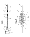
- the earthing electrode is illustrated in fig.1. Nevertheless it is also envisaged that an earthing electrode can be attached to or surround more than one cable, especially where the cables are side by side due to their close proximity to a branching unit into which they are both going to connect. Indeed in such a situation, the attachment of an earthing electrode to one cable of such a pair of cables might risk damaging the casing of the other cable when the cable assembly is being manipulated or laid into the sea.
- Fig.2 illustrates one possible way of providing an additional hydrogen barrier layer in the cable for the part of the cable which is in close proximity to the earthing electrode. Nevertheless it should be pointed out that the hydrogen barrier layer may, depending on the position of the electrode, extend all the way from the electrode into the connections of the branching unit whose equipment is being provided with an earth.
- the provision of a hydrogen barrier a certain distance on either side of the earthing electrode may however provide a satisfactory solution in many instances, and this is what is illustrated in fig.2.
- the hydrogen barrier may be applied to any type of submerged cable carrying fibre optic communications cables and/or power cables, a typical example of which is illustrated in fig.4.
- Fig.4 illustrates a cable which carries optical fibres (11a) and electrical power (11b) in its central core, where the cables are typically set in polyethylene or other suitable material to form a round cross section.
- a copper layer (11c) is then typically provided around this core, which serves to protect the cables being carried from penetration by any gas or fluid.
- This copper layer is then surrounded by a polyethylene casing (11d) which serves to provide electrical insulation and mechanical protection for the fibres being carried, and this on its own would normally suffice as the only mechanical protection required in deep water applications.
- Additional mechanical protection is normally required for installations in shallower waters and is typically provided by one or more layers of steel wire armouring (11f), as is commonly known in the field of cables, which is itself normally encased and protected from the environment in which it operates by an outer layer (11g) which can for example consist of a tar layer or other suitable material.
- 11f steel wire armouring
- the outer casing as well as the layer of steel wire armouring has been temporarily removed to enable a hydrogen barrier layer to be inserted along a predetermined section of cable.
- the hydrogen barrier layer takes the form of metallic or metalised tapes (14) which are applied to the outside of the polyethylene casing (11d) in order to seal this section of the cable from hydrogen penetration.
- the tapes are encapsulated by a layer of synthetic material or resin (15) to ensure that the position of the tapes does not change when the cable is manipulated or laid into the sea, or during the lifetime of the installation.
- the steel armouring wires (16) removed to enable the hydrogen barrier layer to be installed are wrapped around the layer which encapsulates the braided metallic or metalised tapes (14).
- an additional protective layer (17) which seals the region of the cable in which an additional hydrogen barrier layer has been installed, from the environment, in order that the integrity of the outside of the cable remains unaffected by the installation of the hydrogen barrier layer.
- Fig.2 also shows schematically one typical position for an earthing electrode (12a, 12b) relative to the cable, and in particular to the hydrogen barrier layer applied to the cable. This figure also illustrates bend limiters (13a, 13b) which are attached to the cable, modified to include an additional hydrogen barrier layer, on either side of the earthing electrode.
- Fig.3 illustrates a preferred embodiment of the present invention, whereby the earthing electrode comprises two members which are connected together by nuts and bolts (21) although other conventional means of attachment are also envisaged.
- the two members (20a, 20b) of the electrode together form a clamping arrangement, whereby the nuts and bolts are used as the means to urge the members together so as to be able to grip the cable (4) in a sandwich type arrangement.
- the additional hydrogen barrier layer is equally applicable to this configuration of the invention.
- Fig.5 illustrates a metalised heat shrink sleeve which is intended to be inserted over a cable to be protected from hydrogen penetration, in much the same way as the metallic or metalised tapes of the previous embodiment.
- the purpose of the heat-shrink sleeve is to insulate the electrode from the steel armour wires.
- the heat shrink sleeve (10) preferably comprises a ribbed (10a, 10b) internal cavity which is metalised, the ribs ensuring that the metallic layer remains intact after heat treatment to shrink the sleeve onto the cable.
Landscapes
- Physics & Mathematics (AREA)
- General Physics & Mathematics (AREA)
- Optics & Photonics (AREA)
- Engineering & Computer Science (AREA)
- Power Engineering (AREA)
- Laying Of Electric Cables Or Lines Outside (AREA)
- Electrical Discharge Machining, Electrochemical Machining, And Combined Machining (AREA)
- Arc Welding In General (AREA)
- Excavating Of Shafts Or Tunnels (AREA)
- Connector Housings Or Holding Contact Members (AREA)
- Cable Accessories (AREA)
Priority Applications (1)
| Application Number | Priority Date | Filing Date | Title |
|---|---|---|---|
| EP06111252A EP1674908B1 (de) | 2001-10-31 | 2002-10-21 | Erdelektrodeneinheit für eine elektrische Vorrichtung unter Wasser |
Applications Claiming Priority (2)
| Application Number | Priority Date | Filing Date | Title |
|---|---|---|---|
| GBGB0126167.6A GB0126167D0 (en) | 2001-10-31 | 2001-10-31 | Sea earth |
| GB0126167 | 2001-10-31 |
Related Child Applications (1)
| Application Number | Title | Priority Date | Filing Date |
|---|---|---|---|
| EP06111252A Division EP1674908B1 (de) | 2001-10-31 | 2002-10-21 | Erdelektrodeneinheit für eine elektrische Vorrichtung unter Wasser |
Publications (2)
| Publication Number | Publication Date |
|---|---|
| EP1312962A2 true EP1312962A2 (de) | 2003-05-21 |
| EP1312962A3 EP1312962A3 (de) | 2004-09-29 |
Family
ID=9924900
Family Applications (2)
| Application Number | Title | Priority Date | Filing Date |
|---|---|---|---|
| EP06111252A Expired - Lifetime EP1674908B1 (de) | 2001-10-31 | 2002-10-21 | Erdelektrodeneinheit für eine elektrische Vorrichtung unter Wasser |
| EP02292598A Withdrawn EP1312962A3 (de) | 2001-10-31 | 2002-10-21 | Erdelektrodeneinheit für eine elektrische Vorrichtung unter Wasser |
Family Applications Before (1)
| Application Number | Title | Priority Date | Filing Date |
|---|---|---|---|
| EP06111252A Expired - Lifetime EP1674908B1 (de) | 2001-10-31 | 2002-10-21 | Erdelektrodeneinheit für eine elektrische Vorrichtung unter Wasser |
Country Status (6)
| Country | Link |
|---|---|
| US (1) | US7189312B2 (de) |
| EP (2) | EP1674908B1 (de) |
| JP (1) | JP2003151655A (de) |
| AT (1) | ATE401587T1 (de) |
| DE (1) | DE60227719D1 (de) |
| GB (1) | GB0126167D0 (de) |
Cited By (2)
| Publication number | Priority date | Publication date | Assignee | Title |
|---|---|---|---|---|
| EP2574968A1 (de) * | 2011-09-29 | 2013-04-03 | Alcatel Lucent | Unterwasserverbindungseinrichtung mit Erdungseinheit |
| CN110113980A (zh) * | 2016-12-22 | 2019-08-09 | 奇跃公司 | 用于扫描光纤显示器的成形光纤元件的制造方法和系统 |
Families Citing this family (4)
| Publication number | Priority date | Publication date | Assignee | Title |
|---|---|---|---|---|
| EP2092359B1 (de) * | 2006-12-11 | 2013-05-22 | Quasar Federal Systems, Inc. | Kompaktes elektromagnetisches unterwassermesssystem |
| CA2831445C (en) * | 2011-03-28 | 2019-09-24 | Ocean Power Technologies, Inc | Ball and socket power cable connector |
| CN104101973B (zh) * | 2014-07-24 | 2018-03-09 | 深圳市沃尔核材股份有限公司 | 一种绝缘半导开口管及采用该开口管的光缆防护方法 |
| US11785364B2 (en) * | 2021-10-13 | 2023-10-10 | Subcom, Llc | Self-healing submarine links |
Citations (1)
| Publication number | Priority date | Publication date | Assignee | Title |
|---|---|---|---|---|
| EP1014134A1 (de) * | 1998-12-23 | 2000-06-28 | PIRELLI CAVI E SISTEMI S.p.A. | Kabelkrümmungsbegrenzungsvorrichtung |
Family Cites Families (17)
| Publication number | Priority date | Publication date | Assignee | Title |
|---|---|---|---|---|
| US3435124A (en) * | 1966-02-07 | 1969-03-25 | William H Channell | Pedestal and underground terminals for buried cable systems |
| EP0065113A1 (de) | 1981-04-25 | 1982-11-24 | ARCUS ELEKROTECHNIK Alois Schiffmann GmbH | Klemmvorrichtung für mehrere Phasenkurzschliessseile und ein Erdungsseil und Kabelschuh für eine solche Klemmvorrichtung |
| NO850581L (no) * | 1984-02-16 | 1985-08-19 | Standard Telephones Cables Ltd | Undervannskabel |
| JPS6127510A (ja) * | 1984-07-17 | 1986-02-07 | Fujitsu Ltd | 光海底ケ−ブルの海中分岐装置 |
| JPS6158419A (ja) * | 1984-07-26 | 1986-03-25 | 富士通株式会社 | ア−ス構造 |
| US4660909A (en) * | 1985-12-16 | 1987-04-28 | Wilson Daniel P | Remote grounding device for subterranean power systems |
| JPH01201610A (ja) * | 1988-02-08 | 1989-08-14 | Fujitsu Ltd | 光海底ケーブルの接続構造 |
| JP2595287B2 (ja) * | 1988-02-29 | 1997-04-02 | 日本電信電話株式会社 | 海中分岐装置用アース電極付き海底ケーブル |
| US4885428A (en) * | 1988-04-19 | 1989-12-05 | A-1 Construction Company | System for electrical grounding |
| US5217808A (en) * | 1989-11-29 | 1993-06-08 | At&T Bell Laboratories | Water blocked cable portion and methods of making same |
| US5206597A (en) * | 1990-08-27 | 1993-04-27 | The United States Of America As Represented By The Secretary Of The Navy | Capacitive moisture detection apparatus |
| JP2917630B2 (ja) * | 1991-11-27 | 1999-07-12 | 日本電気株式会社 | 海底ケーブル用接地端末構造 |
| SE506257C2 (sv) | 1993-06-23 | 1997-11-24 | Permascand Ab | Anordning och förfarande för överföring av högspänd likström |
| IT1291526B1 (it) * | 1997-04-10 | 1999-01-11 | Pirelli Cavi S P A Ora Pirelli | Terminale secco per cavo elettrico |
| GB9912746D0 (en) * | 1999-06-01 | 1999-08-04 | Cit Alcatel | A submarine casing |
| US6288972B1 (en) * | 1999-06-03 | 2001-09-11 | Mike Norris | Cleated boot for marine seismic cables |
| US6809506B2 (en) * | 2001-03-26 | 2004-10-26 | The United States Of America As Represented By The Secretary Of The Navy | Corrosion sensor loudspeaker for active noise control |
-
2001
- 2001-10-31 GB GBGB0126167.6A patent/GB0126167D0/en not_active Ceased
-
2002
- 2002-10-21 AT AT06111252T patent/ATE401587T1/de not_active IP Right Cessation
- 2002-10-21 EP EP06111252A patent/EP1674908B1/de not_active Expired - Lifetime
- 2002-10-21 DE DE60227719T patent/DE60227719D1/de not_active Expired - Lifetime
- 2002-10-21 EP EP02292598A patent/EP1312962A3/de not_active Withdrawn
- 2002-10-25 JP JP2002311328A patent/JP2003151655A/ja active Pending
- 2002-10-29 US US10/282,175 patent/US7189312B2/en not_active Expired - Lifetime
Patent Citations (1)
| Publication number | Priority date | Publication date | Assignee | Title |
|---|---|---|---|---|
| EP1014134A1 (de) * | 1998-12-23 | 2000-06-28 | PIRELLI CAVI E SISTEMI S.p.A. | Kabelkrümmungsbegrenzungsvorrichtung |
Cited By (5)
| Publication number | Priority date | Publication date | Assignee | Title |
|---|---|---|---|---|
| EP2574968A1 (de) * | 2011-09-29 | 2013-04-03 | Alcatel Lucent | Unterwasserverbindungseinrichtung mit Erdungseinheit |
| WO2013045320A1 (en) * | 2011-09-29 | 2013-04-04 | Alcatel Lucent | Underwater connection assembly with earthing unit |
| CN103827720A (zh) * | 2011-09-29 | 2014-05-28 | 阿尔卡特朗讯 | 具有接地单元的水下连接组件 |
| US9196974B2 (en) | 2011-09-29 | 2015-11-24 | Alcatel Lucent | Underwater connection assembly for use in underwater communication systems |
| CN110113980A (zh) * | 2016-12-22 | 2019-08-09 | 奇跃公司 | 用于扫描光纤显示器的成形光纤元件的制造方法和系统 |
Also Published As
| Publication number | Publication date |
|---|---|
| EP1312962A3 (de) | 2004-09-29 |
| DE60227719D1 (de) | 2008-08-28 |
| EP1674908A1 (de) | 2006-06-28 |
| ATE401587T1 (de) | 2008-08-15 |
| US7189312B2 (en) | 2007-03-13 |
| JP2003151655A (ja) | 2003-05-23 |
| GB0126167D0 (en) | 2002-01-02 |
| US20030102212A1 (en) | 2003-06-05 |
| EP1674908B1 (de) | 2008-07-16 |
Similar Documents
| Publication | Publication Date | Title |
|---|---|---|
| US7381900B2 (en) | Power cable for direct electric heating system | |
| US5125061A (en) | Undersea telecommunications cable having optical fibers in a tube | |
| US7629535B2 (en) | Electric submarine power cable and system for direct electric heating | |
| US6326550B1 (en) | Cable seal | |
| US20050054228A1 (en) | Mid-line connector and method for pipe-in-pipe electrical heating | |
| US11170915B2 (en) | Subsea cable system and a method for supplying electrical power to a subsea device | |
| CA2350586A1 (en) | Cable system for use in hazardous environments | |
| EP1674908B1 (de) | Erdelektrodeneinheit für eine elektrische Vorrichtung unter Wasser | |
| CN103701493B (zh) | 海底有中继海缆传输系统单极缆单端供电的实现方法 | |
| US12567519B2 (en) | Power cable system having different conductor connecting part, and power cable connection method having different conductors | |
| US6434317B1 (en) | Pressure vessel assembly | |
| US8260106B2 (en) | Sealed optoelectronic isolation connection device and sealed cabin | |
| NZ240954A (en) | Fibre optic subsea cable splice box: armour wire terminations in pivot heads hinged to housing | |
| KR20210106762A (ko) | 관로탐사선을 구비한 합성수지관 | |
| CN111509657A (zh) | 一种海缆中间接头 | |
| CN213652656U (zh) | 线状阳极组件 | |
| CN112195473B (zh) | 管道内壁用通电保护装置、施工方法及加工方法 | |
| US20250286360A1 (en) | Rigid sea joint system | |
| Bin et al. | Design Concept and Experience for the Supply, Install and Commissioning of 132kV XLPE Submarine Cable from Kuala Perlis to Teluk Apau, Kedah Darul Aman, Malaysia | |
| WO2007064223A1 (en) | Method and device for preventing water ingress to critical lines in umbilical | |
| NO20210762A1 (en) | An umbilical cable system and appurtenant method | |
| CN121484752A (zh) | 一种海缆柔性续接方法 | |
| CN121709337A (zh) | 一种兼具防腐蚀与抗干扰的双层屏蔽护套控制电缆 | |
| Bow et al. | Chemical Moisture Barrier Cable for Underground Systems | |
| KR20240156300A (ko) | 적응형 강성 해양 조인트 키트 |
Legal Events
| Date | Code | Title | Description |
|---|---|---|---|
| PUAI | Public reference made under article 153(3) epc to a published international application that has entered the european phase |
Free format text: ORIGINAL CODE: 0009012 |
|
| AK | Designated contracting states |
Designated state(s): AT BE BG CH CY CZ DE DK EE ES FI FR GB GR IE IT LI LU MC NL PT SE SK TR |
|
| AX | Request for extension of the european patent |
Extension state: AL LT LV MK RO SI |
|
| PUAL | Search report despatched |
Free format text: ORIGINAL CODE: 0009013 |
|
| AK | Designated contracting states |
Kind code of ref document: A3 Designated state(s): AT BE BG CH CY CZ DE DK EE ES FI FR GB GR IE IT LI LU MC NL PT SE SK TR |
|
| AX | Request for extension of the european patent |
Extension state: AL LT LV MK RO SI |
|
| 17P | Request for examination filed |
Effective date: 20041216 |
|
| 17Q | First examination report despatched |
Effective date: 20050110 |
|
| AKX | Designation fees paid |
Designated state(s): AT BE BG CH CY CZ DE DK EE ES FI FR GB GR IE IT LI LU MC NL PT SE SK TR |
|
| STAA | Information on the status of an ep patent application or granted ep patent |
Free format text: STATUS: THE APPLICATION IS DEEMED TO BE WITHDRAWN |
|
| 18D | Application deemed to be withdrawn |
Effective date: 20060317 |