EP1313076A2 - Dispositif de sécurité et système d'alarme d'intrusion - Google Patents
Dispositif de sécurité et système d'alarme d'intrusion Download PDFInfo
- Publication number
- EP1313076A2 EP1313076A2 EP02380191A EP02380191A EP1313076A2 EP 1313076 A2 EP1313076 A2 EP 1313076A2 EP 02380191 A EP02380191 A EP 02380191A EP 02380191 A EP02380191 A EP 02380191A EP 1313076 A2 EP1313076 A2 EP 1313076A2
- Authority
- EP
- European Patent Office
- Prior art keywords
- signal
- intrusion
- indicating
- alarm
- generating
- Prior art date
- Legal status (The legal status is an assumption and is not a legal conclusion. Google has not performed a legal analysis and makes no representation as to the accuracy of the status listed.)
- Withdrawn
Links
Images


Classifications
-
- G—PHYSICS
- G08—SIGNALLING
- G08B—SIGNALLING SYSTEMS, e.g. PERSONAL CALLING SYSTEMS; ORDER TELEGRAPHS; ALARM SYSTEMS
- G08B25/00—Alarm systems in which the location of the alarm condition is signalled to a central station, e.g. fire or police telegraphic systems
- G08B25/01—Alarm systems in which the location of the alarm condition is signalled to a central station, e.g. fire or police telegraphic systems characterised by the transmission medium
- G08B25/10—Alarm systems in which the location of the alarm condition is signalled to a central station, e.g. fire or police telegraphic systems characterised by the transmission medium using wireless transmission systems
-
- G—PHYSICS
- G08—SIGNALLING
- G08B—SIGNALLING SYSTEMS, e.g. PERSONAL CALLING SYSTEMS; ORDER TELEGRAPHS; ALARM SYSTEMS
- G08B29/00—Checking or monitoring of signalling or alarm systems; Prevention or correction of operating errors, e.g. preventing unauthorised operation
- G08B29/02—Monitoring continuously signalling or alarm systems
- G08B29/06—Monitoring of the line circuits, e.g. signalling of line faults
- G08B29/08—Signalling of tampering with the line circuit
Definitions
- the invention is encompassed in the field of intrusion-alarm systems.
- Intrusion-alarm systems which are intended to detect an intruder and to generate a corresponding alarm, with the aim of surprising the intruders and/or of making it possible to detain them.
- This type of "anti-theft" system provided as much for domestic as well as industrial use, for example in industrial parks, etc, may include a number of peripheral or accessory devices.
- the peripheral devices may include intrusion detectors, for example, volumetric detectors (which may be based, for example, on infrared, ultrasonic and/or microwave detectors), perimeter detectors (for example, electrical switches, photoelectric cells), etc, as well as alarm-signal generators, for example, independently powered external sirens (that is to say, sirens equipped with an energy source, with a view to not being dependent on the integrity of the general electrical supply network), telephone dialers (devices which are programmed such that, when they receive an alarm-raising signal, they dial a preprogrammed telephone number and transmit a message to an addressee, for example, to an alarm center of a security company), etc. All the peripheral devices can be connected to a central base in which information is received from the detectors and from which signals are sent for raising an alarm to the alarm-signal generating peripheral devices.
- intrusion detectors for example, volumetric detectors (which may be based, for example, on infrared, ultrasonic and/or microwave detectors), perimeter detectors
- the peripheral devices are connected to the central base by means of multi-way cables, such that the installation of an alarm system requires the corresponding installation of cables, which, in its turn, implies the corresponding costs and practical difficulties of installation. That being so, the traditional cable system may turn out to be unattractive, especially when it relates to an installation in which some peripheral devices have to be installed at a considerable distance from the central base.
- the peripheral devices and the central base include means for communication between said peripheral devices and the central base via coded signals which are transmitted by radio waves (at radio frequency).
- the central base includes means for receiving radio-frequency signals and means for decoding a coded signal received by said receiving means.
- the intrusion detectors include radio-frequency signal transmitters, which send out signals coded on the basis of a detected condition.
- the base station has means for establishing, on the basis of the decoded signals received, whether an alarm condition exists and, if said alarm condition does exist, activating at least one device for generating an alarm signal.
- the device for generating the alarm signal which may be an external siren or a telephone dialer, may have available means for receiving an alarm-raising signal from the central base, by radio waves and/or by other means.
- All the peripheral devices may include batteries which guarantee them a degree of independence from an external energy source.
- the invention relates to a device in accordance with claim 1 and to a system in accordance with claim 7.
- Preferred embodiments of the invention are defined in the dependent claims.
- the device comprises:
- the radio-frequency detection means advantageously consist of a conventional radio-frequency detector.
- the radio-frequency detection means can be configured to detect a set frequency (for example, the frequency at which an alarm system incorporating the device operates, for example the frequency of 433.92 MHz) or any frequency within a range of frequencies.
- the means for generating a signal indicating a possible sabotage, when the radio-frequency detection means detect a radio frequency over a defined time may consist of a logic circuit associated with the radio-frequency detection means and configured in such a way that, when a radio-frequency signal is detected for a period longer than a defined threshold, it changes the level of a logic output, for example from "0" to "1".
- the means for detecting an intrusion-indicating condition may consist of any conventional device capable of detecting an intrusion condition, for example one or more infrared, ultrasonic, optical, microwave, electromagnetic, etc, detectors. It preferably uses a subsonic or vibration sensor, that is to say, a vibration detector intended to detect the vibrations created by an intruder.
- the means for detecting an intrusion-indicating condition may also consist of other types of detectors, including a combination of detectors of different types, for example, of a combination of "active" detectors (which send out signals and which, for example, receive reflections of said signals against nearby objects) and "passive" detectors (which detect vibrations caused by an intruder, infrared radiation emitted by him or her, etc), which generate signals which are analyzed separately and/or in combination.
- the sensitivity of the means for detecting an intrusion-indicating condition is preferably set up on the basis of the particular conditions of each case, for example, on the basis of the area or volume of the protected area, of the level of ambient noise, etc.
- the means for generating an intrusion-indicating signal when the means for detecting an intrusion-indicating condition detect an intrusion-indicating condition may consist of a simple logic circuit associated with the means for detecting an intrusion-indicating condition; when said detection means detect the intrusion-indicating condition (for example, subsonic vibrations (for example, at a frequency of between 0.2 and 2 Hz) caused by an intruder), the means for generating an intrusion-indicating signal can change the level of the logic output, for example from "0" to "1".
- the means for generating an intrusion-indicating signal may also include means for carrying out a more complex analysis of signals originating from the means for detecting an intrusion-indicating condition, for example, means for carrying out an analysis of signals originating from various detectors and, depending on the results of said analysis, for generating the intrusion-indicating signal.
- the analysis may include an analysis of signals picked up by a subsonic detector and of signals picked up by a heat or infrared radiation detector, and the intrusion-indicating signal could be generated, for example, if, within a defined period of time which follows a detection of vibrations (caused, for example, by the opening of a door and/or window) the presence of an object with a temperature higher than a predetermined threshold is detected (which may be indicative of the presence of a human being).
- the means for generating an alarm-raising signal in the event of the signal indicating a possible sabotage and the intrusion-indicating signal being generated may consist of a logic circuit connected to the logic outputs mentioned above.
- said means for generating an alarm-raising signal may consist of a simple "AND” logic gate with two inputs and one output; the two inputs can be coupled to the two logic outputs mentioned above. That being so, when said two outputs change their logic level “0" to "1", the output of said "AND” logic gate also changes logic level, from “0" to "1", independently of which of the two outputs has changed level first. The change from "0" to "1” of the output of said "AND” logic gate may constitute the alarm-raising signal.
- This signal is applied to a device for generating an alarm signal, for example, to an independently-powered siren which will emit the corresponding alarm sound, to a telephone dialer which dials the number of an alarm center or of a security firm, etc.
- the means for generating a signal indicating a possible sabotage when the radio-frequency detection means detect a radio frequency over a defined time are preferably produced as an electronic module which incorporates or which is coupled to the radio-frequency detection means and to the means for detecting an intrusion-indicating condition, and which has an output available on which the alarm-raising signal appears.
- Said output may be connected to a peripheral generating an alarm signal (for example, to an independently-powered siren which will emit the corresponding alarm sound, to a telephone dialer which dials the number of an alarm center, of a security firm, etc), or to an appropriate input of a central base of an alarm system, in such a way that the alarm-raising signal applied to said input causes the central base, in its turn, to generate the signals necessary for generating an alarm signal (by means of a siren, telephone dialer, etc).
- a peripheral generating an alarm signal for example, to an independently-powered siren which will emit the corresponding alarm sound, to a telephone dialer which dials the number of an alarm center, of a security firm, etc
- an appropriate input of a central base of an alarm system in such a way that the alarm-raising signal applied to said input causes the central base, in its turn, to generate the signals necessary for generating an alarm signal (by means of a siren, telephone dialer, etc).
- the end product is a device which generates an alarm when a radio-frequency signal which complies with defined conditions (for example, which has an amplitude higher than a defined threshold and/or a defined duration and/or which includes one or more defined frequencies) and an intrusion-indicating condition (for example, subsonic vibrations caused by an intruder) are detected simultaneously (or within a defined time interval).
- defined conditions for example, which has an amplitude higher than a defined threshold and/or a defined duration and/or which includes one or more defined frequencies
- an intrusion-indicating condition for example, subsonic vibrations caused by an intruder
- the device may be configured in such a way that the signal for raising the alarm is generated if the radio frequency and the intrusion-indicating condition are detected at a defined time interval (for example, if a radio frequency is detected first during a time t 1 , and a time t 2 after the detection of the radio frequency has ceased, the intrusion-indicating condition is detected, t 2 being less than a defined threshold) .
- a defined time interval for example, if a radio frequency is detected first during a time t 1 , and a time t 2 after the detection of the radio frequency has ceased, the intrusion-indicating condition is detected, t 2 being less than a defined threshold
- the intrusion-alarm system in accordance with the invention is based on a conventional system which comprises:
- said system also includes a security device in accordance with what was explained above.
- This security device can be coupled to a conventional system as a module which is separate from it, or can be integrated into the system.
- the logic circuits of the security device can be produced in integrated form with the logic circuits of the central base of the system.
- the invention is applicable both to already-existing conventional systems as well as to future systems, in which the device is preferably integrated into the systems.
- Figure 1 reflects an intrusion-alarm system which comprises a subsonic intrusion-detector peripheral (1) which includes a vibrations detector (1a), a perimetral detector peripheral (2) which includes an electric circuit (2a), the breaking or cutting of which (due, for example, to the opening of a door or window) is interpreted as an indication of an intrusion, and a perimetral detector peripheral (3) which includes an electrical circuit (3a) the closing of which (due, for example, to the operation of a door or similar) is interpreted as an intrusion-indicating condition.
- These three detector peripherals (1, 2, 3) are equipped with the corresponding means (1b, 2b, 3b) for sending a coded signal to a central base (4) by radio frequency, when an intrusion-indicating condition is detected.
- the radio frequency used can be of 433.92 MHz.
- the system further includes said central base (4), which includes means (5) for receiving the coded signals from the intrusion-detector peripherals (1, 2, 3) by radio frequency; and means (6) for generating an alarm-raising signal, on the basis of the coded signal received.
- Said alarm-raising signal may be sent, by radio frequency, to an independently-powered siren (7) and directly, via a wire conductor (6), to an independently-powered siren (15) and to the telephone dialer (9).
- the system also includes a security device (17) which comprises: the radio-frequency detection means (10), the means (11) for generating a signal indicating a possible sabotage when the radio-frequency detection means (10) detect a radio frequency over a defined time; the means (12) for detecting an intrusion-indicating condition; the means (13) for generating an intrusion-indicating signal when the means (12) for detecting an intrusion-indicating condition detect an intrusion-indicating condition; and the means (14) for generating an alarm-raising signal in the event that the signal indicating the possible sabotage and the intrusion-indicating signal are generated.
- a security device (17) which comprises: the radio-frequency detection means (10), the means (11) for generating a signal indicating a possible sabotage when the radio-frequency detection means (10) detect a radio frequency over a defined time; the means (12) for detecting an intrusion-indicating condition; the means (13) for generating an intrusion-indicating signal when the means (12) for detecting an intrusion-indicating condition detect an intrusion-indicating condition; and
- the radio-frequency detection means (10) are configured to detect a signal with a frequency which corresponds to a frequency for communication between the intrusion-detector peripherals (1, 2, 3) and the central base, for example a frequency of 433.92 MHz.
- the means (12) for detecting an intrusion-indicating condition comprise a vibrations detector, which is preferably configured to detect subsonic vibrations, at frequencies of 0.2-2 Hz, for example.
- the means (14) for generating an alarm-raising signal are connected to an output which communicates with the independently-powered siren (15) and with the telephone dialer (9) and, moreover, with a radio-frequency transmitter (8) by means of which the alarm-raising signal can be transmitted to the independently-powered siren (7) by radio waves, for the purpose of activating said siren in the event of an alarm.
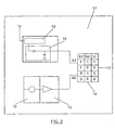
- Figure 2 in schematic form, illustrates the configuration of a preferred embodiment of the security device (17), in which it can be seen how said device includes, on one hand, the radio-frequency detection means (10) and the means (11) for generating a signal (S1) indicating a possible sabotage, and, on the other hand, the means (12) for detecting an intrusion-indicating condition (in this case, a simple microphone sensitive to subsonic vibrations) and the means (13) for generating an intrusion-indicating signal (S2) when the means (12) for detecting an intrusion-indicating condition detect an intrusion-indicating condition (in this case, subsonic vibrations, for example, in the interval 0.2-2 Hz).
- the radio-frequency detection means (10) and the means (11) for generating a signal (S1) indicating a possible sabotage and, on the other hand, the means (12) for detecting an intrusion-indicating condition (in this case, a simple microphone sensitive to subsonic vibrations) and the means (13) for generating an intrusion-indicating signal (S2) when the
- the means (14) for generating an alarm-raising signal are configured as a logic circuit which generates an alarm-raising signal in the event that the signal indicating a possible sabotage and the intrusion-indicating signal are generated.
- FIG 3 illustrates, in schematic form, how the device of the invention (17) in accordance with another preferred embodiment of the invention, is coupled to a conventional central alarm base (18).
Landscapes
- Engineering & Computer Science (AREA)
- Physics & Mathematics (AREA)
- General Physics & Mathematics (AREA)
- Computer Security & Cryptography (AREA)
- Computer Networks & Wireless Communication (AREA)
- Business, Economics & Management (AREA)
- Emergency Management (AREA)
- Burglar Alarm Systems (AREA)
- Alarm Systems (AREA)
Applications Claiming Priority (2)
| Application Number | Priority Date | Filing Date | Title |
|---|---|---|---|
| ES200102368A ES2187293B1 (es) | 2001-10-25 | 2001-10-25 | Dispositivo de seguridad y sistema de alarma de intrusion. |
| ES200102368 | 2001-10-25 |
Publications (2)
| Publication Number | Publication Date |
|---|---|
| EP1313076A2 true EP1313076A2 (fr) | 2003-05-21 |
| EP1313076A3 EP1313076A3 (fr) | 2004-01-14 |
Family
ID=8499291
Family Applications (1)
| Application Number | Title | Priority Date | Filing Date |
|---|---|---|---|
| EP02380191A Withdrawn EP1313076A3 (fr) | 2001-10-25 | 2002-09-10 | Dispositif de sécurité et système d'alarme d'intrusion |
Country Status (3)
| Country | Link |
|---|---|
| US (1) | US20030080867A1 (fr) |
| EP (1) | EP1313076A3 (fr) |
| ES (1) | ES2187293B1 (fr) |
Families Citing this family (3)
| Publication number | Priority date | Publication date | Assignee | Title |
|---|---|---|---|---|
| US7443289B2 (en) * | 2006-05-10 | 2008-10-28 | Honeywell International Inc. | Automatic detection of microphone sabotage in a security system device |
| US12266254B2 (en) * | 2022-09-15 | 2025-04-01 | International Business Machines Corporation | Corroborating device-detected anomalous behavior |
| US12640019B2 (en) | 2023-06-30 | 2026-05-26 | Kidde Fire Protection, Llc | Security system for an environment |
Family Cites Families (10)
| Publication number | Priority date | Publication date | Assignee | Title |
|---|---|---|---|---|
| IT1219751B (it) * | 1988-04-13 | 1990-05-24 | Elkron Spa | Dispositivo rivelatore combinato a microonde e raggi infrarossi particolarmente per sistemi anti intrusione |
| US4833449A (en) * | 1988-07-05 | 1989-05-23 | Gaffigan Robert J | Home security system |
| US5319698A (en) * | 1992-02-11 | 1994-06-07 | Boat Buddy Sentry, Ltd. | Security system |
| US5453733A (en) * | 1992-07-20 | 1995-09-26 | Digital Security Controls Ltd. | Intrusion alarm with independent trouble evaluation |
| FR2700873B1 (fr) * | 1993-01-26 | 1995-04-07 | Edouard Bouquin Paul | Dispositif antibrouillage radio infraudable pour systèmes de surveillance d'intrusions. |
| DE19506385C2 (de) * | 1995-02-23 | 2002-03-07 | Peter John Goddard | Drahtlose Gefahren-Meldeanlage und Meldeverfahren |
| US5793286A (en) * | 1996-01-29 | 1998-08-11 | Seaboard Systems, Inc. | Combined infrasonic and infrared intrusion detection system |
| US5920259A (en) * | 1997-11-10 | 1999-07-06 | Shmuel Hershkovitz | Motion detection with RFI/EMI protection |
| US6191688B1 (en) * | 1999-03-22 | 2001-02-20 | Honeywell International, Inc. | Power-on mask detection method for motion detectors |
| CA2300463C (fr) * | 2000-03-10 | 2009-02-24 | Digital Security Controls Ltd. | Detecteur de mouvement a capteur hyperfrequence et capteur infrarouge passif combines avec analyse anti-masque |
-
2001
- 2001-10-25 ES ES200102368A patent/ES2187293B1/es not_active Expired - Fee Related
-
2002
- 2002-07-22 US US10/202,303 patent/US20030080867A1/en not_active Abandoned
- 2002-09-10 EP EP02380191A patent/EP1313076A3/fr not_active Withdrawn
Also Published As
| Publication number | Publication date |
|---|---|
| ES2187293A1 (es) | 2003-05-16 |
| EP1313076A3 (fr) | 2004-01-14 |
| US20030080867A1 (en) | 2003-05-01 |
| ES2187293B1 (es) | 2004-09-01 |
Similar Documents
| Publication | Publication Date | Title |
|---|---|---|
| US10062251B2 (en) | Doorbell battery systems | |
| US5309144A (en) | Proximity sensing security system | |
| US6359558B1 (en) | Low power audible alarm relay device for a rolling code security system | |
| US6175307B1 (en) | Security system with audible link and two-way communication | |
| US20080309509A1 (en) | Dog bark door bell notification and personal protection system | |
| AU2024202157B2 (en) | A security monitoring system | |
| KR20090029149A (ko) | 침입예방시스템 | |
| KR101986997B1 (ko) | 침입감지 장치 | |
| CN101520933B (zh) | 心跳式探测电子围栏传感器系统的探测方法 | |
| US20030080867A1 (en) | Security device and intrusion-alarm system | |
| US5768343A (en) | Alarm system backup | |
| JP2010282571A (ja) | セキュリティシステム | |
| KR200152279Y1 (ko) | 경계 경보 장치 | |
| CN201191433Y (zh) | 安全综合报警系统 | |
| JP2004265254A (ja) | 侵入者通報装置 | |
| JP4492256B2 (ja) | 防犯装置 | |
| JPH0779291A (ja) | コードレス電話機を用いたセキュリティシステム | |
| KR200210708Y1 (ko) | 도청 감지주파수의 전송장치 | |
| JP2001307238A (ja) | 防犯システム及び切削音検出方法 | |
| RU2674325C2 (ru) | Судовая система охранной сигнализации | |
| KR200374832Y1 (ko) | 홈 보안 시스템 | |
| JP2005107696A (ja) | 防犯システム | |
| JP4196716B2 (ja) | 警報信号出力装置 | |
| JP3483247B2 (ja) | 無線監視システム | |
| KR200254696Y1 (ko) | 공동주택용 방범시스템 |
Legal Events
| Date | Code | Title | Description |
|---|---|---|---|
| PUAI | Public reference made under article 153(3) epc to a published international application that has entered the european phase |
Free format text: ORIGINAL CODE: 0009012 |
|
| AK | Designated contracting states |
Designated state(s): AT BE BG CH CY CZ DE DK EE ES FI FR GB GR IE IT LI LU MC NL PT SE SK TR |
|
| AX | Request for extension of the european patent |
Extension state: AL LT LV MK RO SI |
|
| PUAL | Search report despatched |
Free format text: ORIGINAL CODE: 0009013 |
|
| AK | Designated contracting states |
Kind code of ref document: A3 Designated state(s): AT BE BG CH CY CZ DE DK EE ES FI FR GB GR IE IT LI LU MC NL PT SE SK TR |
|
| AX | Request for extension of the european patent |
Extension state: AL LT LV MK RO SI |
|
| RIC1 | Information provided on ipc code assigned before grant |
Ipc: 7G 08B 29/08 B Ipc: 7G 08B 25/10 A |
|
| AKX | Designation fees paid | ||
| REG | Reference to a national code |
Ref country code: DE Ref legal event code: 8566 |
|
| STAA | Information on the status of an ep patent application or granted ep patent |
Free format text: STATUS: THE APPLICATION IS DEEMED TO BE WITHDRAWN |
|
| 18D | Application deemed to be withdrawn |
Effective date: 20040715 |