EP1313109A2 - Oberflächenmontierbarer elektrischer Widerstand - Google Patents
Oberflächenmontierbarer elektrischer Widerstand Download PDFInfo
- Publication number
- EP1313109A2 EP1313109A2 EP02022650A EP02022650A EP1313109A2 EP 1313109 A2 EP1313109 A2 EP 1313109A2 EP 02022650 A EP02022650 A EP 02022650A EP 02022650 A EP02022650 A EP 02022650A EP 1313109 A2 EP1313109 A2 EP 1313109A2
- Authority
- EP
- European Patent Office
- Prior art keywords
- resistance element
- resistance
- plane
- resistor according
- connection elements
- Prior art date
- Legal status (The legal status is an assumption and is not a legal conclusion. Google has not performed a legal analysis and makes no representation as to the accuracy of the status listed.)
- Withdrawn
Links
Images
Classifications
-
- H—ELECTRICITY
- H01—ELECTRIC ELEMENTS
- H01C—RESISTORS
- H01C1/00—Details
- H01C1/14—Terminals or tapping points specially adapted for resistors; Arrangements of terminals or tapping points on resistors
-
- G—PHYSICS
- G01—MEASURING; TESTING
- G01R—MEASURING ELECTRIC VARIABLES; MEASURING MAGNETIC VARIABLES
- G01R1/00—Details of instruments or arrangements of the types included in groups G01R5/00 - G01R13/00 and G01R31/00
- G01R1/20—Modifications of basic electric elements for use in electric measuring instruments; Structural combinations of such elements with such instruments
- G01R1/203—Resistors used for electric measuring, e.g. decade resistors standards, resistors for comparators, series resistors, shunts
-
- H—ELECTRICITY
- H05—ELECTRIC TECHNIQUES NOT OTHERWISE PROVIDED FOR
- H05K—PRINTED CIRCUITS; CASINGS OR CONSTRUCTIONAL DETAILS OF ELECTRIC APPARATUS; MANUFACTURE OF ASSEMBLAGES OF ELECTRICAL COMPONENTS
- H05K3/00—Apparatus or processes for manufacturing printed circuits
- H05K3/30—Assembling printed circuits with electric components, e.g. with resistors
- H05K3/32—Assembling printed circuits with electric components, e.g. with resistors electrically connecting electric components or wires to printed circuits
- H05K3/34—Assembling printed circuits with electric components, e.g. with resistors electrically connecting electric components or wires to printed circuits by soldering
- H05K3/341—Surface mounted components
- H05K3/3421—Leaded components
- H05K3/3426—Leaded components characterised by the leads
Definitions
- the invention relates to a surface-mountable electrical Resistor according to the preamble of claim 1, a Current measuring arrangement with such a resistor and a method for its manufacture.
- SMD components may be something with their projecting connection elements flat on appropriately arranged Connection areas for example of a circuit board soldered.
- the object of the invention is a resistor or a current measuring arrangement with such a resistor to indicate that the solder joints are less stressed than so far.
- the invention achieves that without changing the advantageous Properties of the known welded resistors reliable solder connections much more durable than before consist.
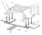
- the SMD measuring resistor shown consists of the metallic one plate-shaped flat resistance element 3 and the two likewise plate-like, but approximately Z-shaped as shown curved connection elements 1 and 2 with parallel to the resistance element lying upper edge strips 21, which are parallel to this End strips 22 and between the edge and end strips 21, 22 extending transversely to the main plane of the resistance element 3 also strip-shaped web parts 23.
- the two Connection elements 1 and 2 are connected to the resistor elements 3 abutting edges or end faces of their edge strips 21 to the opposite edges or end faces 31 and 32 of the resistance element 3 welded.
- the resistance element suitably consists of one of the known for this Copper alloys (e.g. CuMnNi) while the connection elements made of high conductivity metal such as Copper exist.
- the measuring resistor shown in SMD technology e.g. soldered onto a printed circuit 40, as by the Directional arrows of the drawing is indicated and below is explained in more detail.
- this length (or the height of the underside of the resistance element 3 over the Connection areas of the circuit 40) amount to a few mm.
- the length should be at least about three or four times the thickness and is increased mainly by what is possible in practice Limited height.
- the end strips 22 of the resistor are, as shown, through the slots 5, which extend parallel to the main surface planes of the resistance element 3 and the end strips 22 and transversely to the welded end faces through the end strips 22 and, as shown, continue upwards a little in the web part 23 in divides a wide part 22 I and a narrower part 22 U , whereby a four-pole measuring resistor is formed.
- the two parts 22 I are soldered to current connections 41 of relatively wide current conductors 42 of the circuit 40 and the parts 22 U are soldered to separate voltage connections 43 of measuring lines 44.
- the 4-wire arrangement is known per se and customary in current measuring circuits.
- the resistance shown is produced by separation from or punching out from that in EP 0 605 800 or 0 716 427 described long composite material band, which consists of a middle band from the resistance alloy and with its Long edges of welded strips made of metal with high conductivity consists.
- the cutting or punching out can be done in one Punching and bending tool done in which also the bending the originally plate-shaped flat connection elements 1 and 2 can be performed in the Z-shape shown.
- the slots 5 can also be punched out or on others Generated way.
Landscapes
- Engineering & Computer Science (AREA)
- Microelectronics & Electronic Packaging (AREA)
- Details Of Resistors (AREA)
Abstract
Description
Claims (9)
- Oberflächenmontierbarer elektrischer Widerstand, insbesondere niederohmiger Messwiderstand,
mit einem aus einer metallischen Widerstandslegierung bestehenden plattenförmigen Widerstandselement (3)
und mit zwei durch das Widerstandselement voneinander getrennten Anschlusselementen (1, 2) aus Metall hoher Leitfähigkeit, die sich streifenförmig längs zueinander entgegengesetzte Kanten (31, 32) des Widerstandselements (3) erstrecken und an diese Kanten angeschweißt sind,
wobei die Anschlusselemente (1, 2) von der Ebene der einen Hauptfläche des Widerstandselements (3) vorspringen,
dadurch gekennzeichnet, dass die dem Widerstandselement (3) abgewandten Enden (22) der Anschlusselemente (1, 2) unter elastischer Verbiegung der zwischen den Enden (22) und dem Widerstandselement (3) liegenden Teile (23) der Anschlusselemente (1, 2) parallel zu der Hauptflächenebene des Widerstandselements (3) relativ zueinander bewegbar sind. - Widerstand nach Anspruch 1 oder dessen Oberbegriff,
dadurch gekennzeichnet, dass die Länge der streifenförmigen Teile (23) der Anschlusselemente (1, 2), die zwischen deren dem Widerstandselement (3) abgewandten Enden (22) und dem Widerstandselement liegen, in der quer zu dessen Hauptflächenebene verlaufenden Richtung wesentlich größer ist als die senkrecht zu der Hauptflächenebene der streifenförmigen Teile (23) gemessene Dicke dieser Teile (23). - Widerstand nach Anspruch 2, dadurch gekennzeichnet, dass die genannte Länge mindestens das Dreifache der genannten Dicke beträgt.
- Widerstand nach einem der vorangehenden Ansprüche,
dadurch gekennzeichnet, dass die Enden der Anschlusselemente (1, 2) durch wenigstens annähernd parallel zu der Hauptebene des plattenförmigen Widerstandselements (1) abgebogene flache Streifen (22) gebildet sind. - Widerstand nach Anspruch 4, dadurch gekennzeichnet, dass die abgebogenen Endstreifen (22) jeweils durch einen Schlitz (5) in je zwei getrennte Teile (22U, 22I) vorzugsweise unterschiedlicher Größe unterteilt sind, von denen der eine als Stromanschluss und der andere als Messspannungsanschluss des vierpoligen Messwiderstands verwendbar ist.
- Widerstand nach Anspruch 5, dadurch gekennzeichnet, dass die Schlitze (5) parallel zu dessen Hauptflächenebene des Widerstandselements (1) und quer zu dessen mit den Anschlusselementen (1, 2) verschweißten Kanten (32) durch die Endstreifen (22) verlaufen.
- Strommessanordnung mit einem Widerstand nach Anspruch 5 oder 6, der mit seinen abgebogenen Endstreifen (22) auf flachen Leiterbahnen (42, 44) einer Schaltung (40) montiert ist,
wobei der eine Teil (22I) jedes Endstreifens (22) je einen Stromanschluss (41) und sein anderer, vorzugsweise kleinerer Teil (22U) je einen Messspannungsanschluss (43) der Schaltung (40) kontaktiert. - Verfahren zum Herstellen eines Widerstands nach einem der Ansprüche 1 bis 6, dadurch gekennzeichnet, dass
von einem langen Verbundmaterialband, das aus einem mittleren Band aus einer metallischen Widerstandslegierung und mit dessen Längskanten verschweißten Bändern aus einem Metall hoher elektrischer Leitfähigkeit besteht, quer zu der Bandlängsrichtung ein Stück abgetrennt oder ausgestanzt wird
und die beiden aus dem Metall hoher Leitfähigkeit bestehenden Randteile (1, 2) dieses Stücks in eine Z-Form mit quer zu der Ebene des aus der Widerstandslegierung bestehenden Mittelteils (3) abstehenden Stegteilen (23) und parallel zu der Ebene des Mittelteils (3) liegenden Endstreifen (22) gebogen werden. - Verfahren nach Anspruch 8, dadurch gekennzeichnet, dass der Biegevorgang in dem zum Abtrennen oder Ausstanzen verwendeten Werkzeug durchgeführt wird.
Applications Claiming Priority (2)
| Application Number | Priority Date | Filing Date | Title |
|---|---|---|---|
| DE20117650U | 2001-10-29 | ||
| DE20117650U DE20117650U1 (de) | 2001-10-29 | 2001-10-29 | Oberflächenmontierbarer elektrischer Widerstand |
Publications (2)
| Publication Number | Publication Date |
|---|---|
| EP1313109A2 true EP1313109A2 (de) | 2003-05-21 |
| EP1313109A3 EP1313109A3 (de) | 2004-10-20 |
Family
ID=7963372
Family Applications (1)
| Application Number | Title | Priority Date | Filing Date |
|---|---|---|---|
| EP02022650A Withdrawn EP1313109A3 (de) | 2001-10-29 | 2002-10-09 | Oberflächenmontierbarer elektrischer Widerstand |
Country Status (2)
| Country | Link |
|---|---|
| EP (1) | EP1313109A3 (de) |
| DE (1) | DE20117650U1 (de) |
Cited By (9)
| Publication number | Priority date | Publication date | Assignee | Title |
|---|---|---|---|---|
| EP1492130A3 (de) * | 2003-06-26 | 2005-02-09 | Isabellenhütte Heusler GmbH & Co.KG | Widerstandsanordnung, Herstellungsverfahren und Messschaltung |
| WO2008022632A1 (de) * | 2006-08-24 | 2008-02-28 | Conti Temic Microelectronic Gmbh | Elektrisches bauelement, insbesondere messwiderstand sowie verfahren zur herstellung eines derartigen elektrischen bauelements |
| EP1986479A3 (de) * | 2007-04-27 | 2009-08-05 | Omron Corporation | Anschlusssubstrat und Stromerkennungsvorrichtung |
| CN101483091B (zh) * | 2008-01-08 | 2012-07-04 | 英飞凌科技股份有限公司 | 包括分流电阻器的装置及其制作方法 |
| US9035736B2 (en) | 2013-03-27 | 2015-05-19 | General Electric Company | Magnetic device having integrated current sensing element and methods of assembling same |
| US9400294B2 (en) | 2009-09-04 | 2016-07-26 | Vishay Dale Electronics, Llc | Resistor with temperature coefficient of resistance (TCR) compensation |
| CN113140380A (zh) * | 2020-01-17 | 2021-07-20 | 威兰德沃克公开股份有限公司 | 电阻器阵列、具有电阻器阵列的测量电路以及制造用于电阻器阵列的带状材料复合体的方法 |
| US11555831B2 (en) | 2020-08-20 | 2023-01-17 | Vishay Dale Electronics, Llc | Resistors, current sense resistors, battery shunts, shunt resistors, and methods of making |
| EP4500589A4 (de) * | 2022-03-30 | 2026-04-01 | Analog Devices Inc | Elektronische vorrichtung |
Families Citing this family (5)
| Publication number | Priority date | Publication date | Assignee | Title |
|---|---|---|---|---|
| US8018310B2 (en) | 2006-09-27 | 2011-09-13 | Vishay Dale Electronics, Inc. | Inductor with thermally stable resistance |
| DE102007033182B4 (de) * | 2007-07-13 | 2012-11-29 | Auto-Kabel Management Gmbh | Kraftfahrzeugbatteriesensorelement sowie Verfahren zur Herstellung eines Kraftfahrzeugbatteriesensorelements |
| JP5619663B2 (ja) | 2011-03-31 | 2014-11-05 | 古河電気工業株式会社 | シャント抵抗器の接続端子、及びバッテリー状態検知装置 |
| DE102013009726A1 (de) | 2013-06-10 | 2014-12-11 | Isabellenhütte Heusler Gmbh & Co. Kg | Stanzteil zur Herstellung eines elektrischen Widerstands, Stromsensor und entsprechendes Herstellungsverfahren |
| DE102021122491B4 (de) | 2021-08-31 | 2023-03-30 | Isabellenhütte Heusler Gmbh & Co. Kg | Strommesswiderstand |
Family Cites Families (3)
| Publication number | Priority date | Publication date | Assignee | Title |
|---|---|---|---|---|
| AT374147B (de) * | 1982-04-06 | 1984-03-26 | Uher Ag | Messwiderstand fuer einen elektronischen blinkgeber |
| US5287083A (en) * | 1992-03-30 | 1994-02-15 | Dale Electronics, Inc. | Bulk metal chip resistor |
| US5999085A (en) * | 1998-02-13 | 1999-12-07 | Vishay Dale Electronics, Inc. | Surface mounted four terminal resistor |
-
2001
- 2001-10-29 DE DE20117650U patent/DE20117650U1/de not_active Expired - Lifetime
-
2002
- 2002-10-09 EP EP02022650A patent/EP1313109A3/de not_active Withdrawn
Cited By (19)
| Publication number | Priority date | Publication date | Assignee | Title |
|---|---|---|---|---|
| EP1492130A3 (de) * | 2003-06-26 | 2005-02-09 | Isabellenhütte Heusler GmbH & Co.KG | Widerstandsanordnung, Herstellungsverfahren und Messschaltung |
| US7170295B2 (en) | 2003-06-26 | 2007-01-30 | Isabellenhutte Heusler Gmbh & Co. Kg | Resistor arrangement, manufacturing method, and measurement circuit |
| WO2008022632A1 (de) * | 2006-08-24 | 2008-02-28 | Conti Temic Microelectronic Gmbh | Elektrisches bauelement, insbesondere messwiderstand sowie verfahren zur herstellung eines derartigen elektrischen bauelements |
| EP1986479A3 (de) * | 2007-04-27 | 2009-08-05 | Omron Corporation | Anschlusssubstrat und Stromerkennungsvorrichtung |
| CN101483091B (zh) * | 2008-01-08 | 2012-07-04 | 英飞凌科技股份有限公司 | 包括分流电阻器的装置及其制作方法 |
| US9779860B2 (en) | 2009-09-04 | 2017-10-03 | Vishay Dale Electronics, Llc | Resistor with temperature coefficient of resistance (TCR) compensation |
| EP4280232A3 (de) * | 2009-09-04 | 2024-06-05 | Vishay Dale Electronics, LLC | Widerstand mit temperaturkoeffizientenkompensation des widerstands (tcr) |
| US9400294B2 (en) | 2009-09-04 | 2016-07-26 | Vishay Dale Electronics, Llc | Resistor with temperature coefficient of resistance (TCR) compensation |
| US12009127B2 (en) | 2009-09-04 | 2024-06-11 | Vishay Dale Electronics, Llc | Resistor with temperature coefficient of resistance (TCR) compensation |
| EP2474008A4 (de) * | 2009-09-04 | 2018-03-28 | Vishay Dale Electronics, Inc. | Widerstand mit widerstandstemperaturkoeffizienten-kompensation |
| US10217550B2 (en) | 2009-09-04 | 2019-02-26 | Vishay Dale Electronics, Llc | Resistor with temperature coefficient of resistance (TCR) compensation |
| US10796826B2 (en) | 2009-09-04 | 2020-10-06 | Vishay Dale Electronics, Llc | Resistor with temperature coefficient of resistance (TCR) compensation |
| US11562838B2 (en) | 2009-09-04 | 2023-01-24 | Vishay Dale Electronics, Llc | Resistor with temperature coefficient of resistance (TCR) compensation |
| US9171667B2 (en) | 2013-03-27 | 2015-10-27 | General Electric Company | Magnetic device having integrated current sensing element and methods of assembling same |
| US9035736B2 (en) | 2013-03-27 | 2015-05-19 | General Electric Company | Magnetic device having integrated current sensing element and methods of assembling same |
| CN113140380A (zh) * | 2020-01-17 | 2021-07-20 | 威兰德沃克公开股份有限公司 | 电阻器阵列、具有电阻器阵列的测量电路以及制造用于电阻器阵列的带状材料复合体的方法 |
| US11555831B2 (en) | 2020-08-20 | 2023-01-17 | Vishay Dale Electronics, Llc | Resistors, current sense resistors, battery shunts, shunt resistors, and methods of making |
| US12196783B2 (en) | 2020-08-20 | 2025-01-14 | Vishay Dale Electronics, Llc | Resistors, current sense resistors, battery shunts, shunt resistors, and methods of making |
| EP4500589A4 (de) * | 2022-03-30 | 2026-04-01 | Analog Devices Inc | Elektronische vorrichtung |
Also Published As
| Publication number | Publication date |
|---|---|
| DE20117650U1 (de) | 2003-03-13 |
| EP1313109A3 (de) | 2004-10-20 |
Similar Documents
| Publication | Publication Date | Title |
|---|---|---|
| EP0605800B1 (de) | Verfahren zum Herstellen von Widerständen aus Verbundmaterial und insbesondere nach diesem Verfahren hergestellte Widerstände | |
| DE4310288B4 (de) | Oberflächenmontierbarer Widerstand | |
| DE1440860C3 (de) | Verbund Metallstreifen | |
| DE112016002705T5 (de) | Widerstand und Verfahren zum Herstellen desselben | |
| DE69525867T2 (de) | Thermodruckkopf | |
| EP1941520B1 (de) | Widerstand, insbesondere smd-widerstand, und zugehöriges herstellungsverfahren | |
| DE112018000816B4 (de) | Stromerfassungsvorrichtung und Stromerfassungswiderstand | |
| EP1313109A2 (de) | Oberflächenmontierbarer elektrischer Widerstand | |
| DE202008018126U1 (de) | Lötanschlusselement | |
| DE112014006848T5 (de) | Verfahren zum Verbinden eines Anschlusselements und einer elektrischen Leitung und ein Verbindungsanschlusselement für eine elektrische Leitung | |
| DE10111389A1 (de) | Verbund aus flächigen Leiterelementen | |
| DE3237980C2 (de) | Verfahren zur Herstellung einer Kontaktanordnung | |
| DE69838604T2 (de) | Gedruckte platte und verfahren zu deren herstellung | |
| WO2009121697A1 (de) | Stromführungsbauteil mit einem träger, leiterbahnen und leiterplättchen | |
| WO2008022632A1 (de) | Elektrisches bauelement, insbesondere messwiderstand sowie verfahren zur herstellung eines derartigen elektrischen bauelements | |
| DE69400980T2 (de) | Elektrische Anschlussvorrichtung und zugehöriges Herstellungsverfahren | |
| DE4236086C1 (de) | Elektrischer Widerstand und Verfahren zur Herstellung eines solchen Widerstands | |
| DE2423932C3 (de) | Bauelement für Schalt- und/oder Trennleisten in Verteilern für Fernmeldeanlagen, insbesondere Fernsprechvermittlungsanlagen | |
| EP1229558A2 (de) | Herstellung niederohmiger Widerstände | |
| DE10338041B3 (de) | Elektrischer Widerstand und Verfahren zum Herstellen von Widerständen | |
| WO2024256116A1 (de) | Verfahren zur herstellung einer widerstandsanordnung mit einem kontaktelement und widerstandsanordnung mit einem kontaktelement | |
| DE9320911U1 (de) | Elektrischer Widerstand | |
| DE102018207074A1 (de) | Elektrische Vorrichtung | |
| EP1283528B1 (de) | Niederohmiger elektrischer Widerstand und Verfahren zur Herstellung solcher Widerstände | |
| DE69704025T2 (de) | Verfahren zur herstellung eines elektromechanischen relais |
Legal Events
| Date | Code | Title | Description |
|---|---|---|---|
| PUAI | Public reference made under article 153(3) epc to a published international application that has entered the european phase |
Free format text: ORIGINAL CODE: 0009012 |
|
| AK | Designated contracting states |
Designated state(s): AT BE BG CH CY CZ DE DK EE ES FI FR GB GR IE IT LI LU MC NL PT SE SK TR |
|
| AX | Request for extension of the european patent |
Extension state: AL LT LV MK RO SI |
|
| PUAL | Search report despatched |
Free format text: ORIGINAL CODE: 0009013 |
|
| AK | Designated contracting states |
Kind code of ref document: A3 Designated state(s): AT BE BG CH CY CZ DE DK EE ES FI FR GB GR IE IT LI LU MC NL PT SE SK TR |
|
| AX | Request for extension of the european patent |
Extension state: AL LT LV MK RO SI |
|
| RAP1 | Party data changed (applicant data changed or rights of an application transferred) |
Owner name: ISABELLENHUETTE HEUSLER GMBH & CO.KG |
|
| AKX | Designation fees paid | ||
| REG | Reference to a national code |
Ref country code: DE Ref legal event code: 8566 |
|
| STAA | Information on the status of an ep patent application or granted ep patent |
Free format text: STATUS: THE APPLICATION IS DEEMED TO BE WITHDRAWN |
|
| 18D | Application deemed to be withdrawn |
Effective date: 20050421 |