EP1313156A2 - Zusammengesetzte Batterie - Google Patents
Zusammengesetzte Batterie Download PDFInfo
- Publication number
- EP1313156A2 EP1313156A2 EP02023208A EP02023208A EP1313156A2 EP 1313156 A2 EP1313156 A2 EP 1313156A2 EP 02023208 A EP02023208 A EP 02023208A EP 02023208 A EP02023208 A EP 02023208A EP 1313156 A2 EP1313156 A2 EP 1313156A2
- Authority
- EP
- European Patent Office
- Prior art keywords
- assembled battery
- bus bar
- tabs
- unit cells
- size
- Prior art date
- Legal status (The legal status is an assumption and is not a legal conclusion. Google has not performed a legal analysis and makes no representation as to the accuracy of the status listed.)
- Withdrawn
Links
- 238000005304 joining Methods 0.000 claims abstract description 27
- 238000000034 method Methods 0.000 claims description 18
- 239000000463 material Substances 0.000 claims description 8
- 238000005452 bending Methods 0.000 claims description 6
- 210000004027 cell Anatomy 0.000 description 146
- 238000003466 welding Methods 0.000 description 15
- RYGMFSIKBFXOCR-UHFFFAOYSA-N Copper Chemical compound [Cu] RYGMFSIKBFXOCR-UHFFFAOYSA-N 0.000 description 9
- 229910052802 copper Inorganic materials 0.000 description 9
- 239000010949 copper Substances 0.000 description 9
- PXHVJJICTQNCMI-UHFFFAOYSA-N Nickel Chemical compound [Ni] PXHVJJICTQNCMI-UHFFFAOYSA-N 0.000 description 8
- 230000000694 effects Effects 0.000 description 7
- 238000004519 manufacturing process Methods 0.000 description 5
- 210000005056 cell body Anatomy 0.000 description 4
- 239000002131 composite material Substances 0.000 description 4
- 229910052759 nickel Inorganic materials 0.000 description 4
- 229910052782 aluminium Inorganic materials 0.000 description 3
- XAGFODPZIPBFFR-UHFFFAOYSA-N aluminium Chemical compound [Al] XAGFODPZIPBFFR-UHFFFAOYSA-N 0.000 description 3
- 238000005516 engineering process Methods 0.000 description 3
- 229910052751 metal Inorganic materials 0.000 description 3
- 239000002184 metal Substances 0.000 description 3
- CURLTUGMZLYLDI-UHFFFAOYSA-N Carbon dioxide Chemical compound O=C=O CURLTUGMZLYLDI-UHFFFAOYSA-N 0.000 description 2
- HBBGRARXTFLTSG-UHFFFAOYSA-N Lithium ion Chemical compound [Li+] HBBGRARXTFLTSG-UHFFFAOYSA-N 0.000 description 2
- 230000015556 catabolic process Effects 0.000 description 2
- 230000000052 comparative effect Effects 0.000 description 2
- 230000010354 integration Effects 0.000 description 2
- 229910001416 lithium ion Inorganic materials 0.000 description 2
- 239000002905 metal composite material Substances 0.000 description 2
- 235000008733 Citrus aurantifolia Nutrition 0.000 description 1
- 239000004677 Nylon Substances 0.000 description 1
- 240000006909 Tilia x europaea Species 0.000 description 1
- 235000011941 Tilia x europaea Nutrition 0.000 description 1
- 238000010521 absorption reaction Methods 0.000 description 1
- 229910045601 alloy Inorganic materials 0.000 description 1
- 239000000956 alloy Substances 0.000 description 1
- 229910002092 carbon dioxide Inorganic materials 0.000 description 1
- 239000001569 carbon dioxide Substances 0.000 description 1
- 239000004020 conductor Substances 0.000 description 1
- 230000005611 electricity Effects 0.000 description 1
- 230000007613 environmental effect Effects 0.000 description 1
- 230000002349 favourable effect Effects 0.000 description 1
- 239000002803 fossil fuel Substances 0.000 description 1
- 239000000446 fuel Substances 0.000 description 1
- 239000004571 lime Substances 0.000 description 1
- 229920001778 nylon Polymers 0.000 description 1
- 230000000149 penetrating effect Effects 0.000 description 1
- 229920000642 polymer Polymers 0.000 description 1
- 230000005855 radiation Effects 0.000 description 1
- 230000035939 shock Effects 0.000 description 1
- 239000010454 slate Substances 0.000 description 1
Images


Classifications
-
- H—ELECTRICITY
- H01—ELECTRIC ELEMENTS
- H01M—PROCESSES OR MEANS, e.g. BATTERIES, FOR THE DIRECT CONVERSION OF CHEMICAL ENERGY INTO ELECTRICAL ENERGY
- H01M50/00—Constructional details or processes of manufacture of the non-active parts of electrochemical cells other than fuel cells, e.g. hybrid cells
- H01M50/20—Mountings; Secondary casings or frames; Racks, modules or packs; Suspension devices; Shock absorbers; Transport or carrying devices; Holders
- H01M50/233—Mountings; Secondary casings or frames; Racks, modules or packs; Suspension devices; Shock absorbers; Transport or carrying devices; Holders characterised by physical properties of casings or racks, e.g. dimensions
- H01M50/24—Mountings; Secondary casings or frames; Racks, modules or packs; Suspension devices; Shock absorbers; Transport or carrying devices; Holders characterised by physical properties of casings or racks, e.g. dimensions adapted for protecting batteries from their environment, e.g. from corrosion
-
- H—ELECTRICITY
- H01—ELECTRIC ELEMENTS
- H01M—PROCESSES OR MEANS, e.g. BATTERIES, FOR THE DIRECT CONVERSION OF CHEMICAL ENERGY INTO ELECTRICAL ENERGY
- H01M50/00—Constructional details or processes of manufacture of the non-active parts of electrochemical cells other than fuel cells, e.g. hybrid cells
- H01M50/20—Mountings; Secondary casings or frames; Racks, modules or packs; Suspension devices; Shock absorbers; Transport or carrying devices; Holders
- H01M50/204—Racks, modules or packs for multiple batteries or multiple cells
- H01M50/207—Racks, modules or packs for multiple batteries or multiple cells characterised by their shape
- H01M50/209—Racks, modules or packs for multiple batteries or multiple cells characterised by their shape adapted for prismatic or rectangular cells
-
- H—ELECTRICITY
- H01—ELECTRIC ELEMENTS
- H01M—PROCESSES OR MEANS, e.g. BATTERIES, FOR THE DIRECT CONVERSION OF CHEMICAL ENERGY INTO ELECTRICAL ENERGY
- H01M50/00—Constructional details or processes of manufacture of the non-active parts of electrochemical cells other than fuel cells, e.g. hybrid cells
- H01M50/50—Current conducting connections for cells or batteries
- H01M50/502—Interconnectors for connecting terminals of adjacent batteries; Interconnectors for connecting cells outside a battery casing
- H01M50/507—Interconnectors for connecting terminals of adjacent batteries; Interconnectors for connecting cells outside a battery casing comprising an arrangement of two or more busbars within a container structure, e.g. busbar modules
-
- H—ELECTRICITY
- H01—ELECTRIC ELEMENTS
- H01M—PROCESSES OR MEANS, e.g. BATTERIES, FOR THE DIRECT CONVERSION OF CHEMICAL ENERGY INTO ELECTRICAL ENERGY
- H01M50/00—Constructional details or processes of manufacture of the non-active parts of electrochemical cells other than fuel cells, e.g. hybrid cells
- H01M50/50—Current conducting connections for cells or batteries
- H01M50/502—Interconnectors for connecting terminals of adjacent batteries; Interconnectors for connecting cells outside a battery casing
- H01M50/521—Interconnectors for connecting terminals of adjacent batteries; Interconnectors for connecting cells outside a battery casing characterised by the material
- H01M50/522—Inorganic material
-
- Y—GENERAL TAGGING OF NEW TECHNOLOGICAL DEVELOPMENTS; GENERAL TAGGING OF CROSS-SECTIONAL TECHNOLOGIES SPANNING OVER SEVERAL SECTIONS OF THE IPC; TECHNICAL SUBJECTS COVERED BY FORMER USPC CROSS-REFERENCE ART COLLECTIONS [XRACs] AND DIGESTS
- Y02—TECHNOLOGIES OR APPLICATIONS FOR MITIGATION OR ADAPTATION AGAINST CLIMATE CHANGE
- Y02E—REDUCTION OF GREENHOUSE GAS [GHG] EMISSIONS, RELATED TO ENERGY GENERATION, TRANSMISSION OR DISTRIBUTION
- Y02E60/00—Enabling technologies; Technologies with a potential or indirect contribution to GHG emissions mitigation
- Y02E60/10—Energy storage using batteries
Definitions
- the present invention relates to an assembled battery constituted by combining a plurality of secondary battery single cells, and specifically, to an assembled battery which is constituted by combining small-scale secondary cells, and can be publicly used as a battery for driving the motor of an electric vehicle or the like.
- each cell needs to be made very large, and a specialized production line needs to be provided for production.
- a specialized production line needs to be provided for production.
- each cell is very heavy, so that the cells are difficult to handle.
- a unit cell a number of small-scaled cells, which are easy to handle (hereinafter, referred to as a unit cell) are connected to be used in applications of the EV, the HEV, and the FCV.
- a lithium ion secondary battery of high output and high energy density is used as an assembled battery for vehicles for charge and discharge
- an assembled battery in which each group having a plurality of unit cells connected in parallel are connected in series, is used.
- an assembled battery obtains a voltage of 400 V as a whole.
- the utilization of a consumer lithium ion battery becomes favorable.
- the assembled battery for the electric vehicle is always used in a state where vibration is applied thereto. Therefore, vibration resistance is required such that no trouble occurs inside of the unit cell.
- Such troubles include structure breakdown such as breakage of collectors or breakage of collector welding portions, breakage of a connecting tab for electrically connecting the unit cells, and the like.
- the unit cells themselves have sufficient rigidity.
- the rigid unit cells are accommodated in casings and then connected together with bus bars or the like. Therefore, the casing in the prior art is hardly applicable to a case where a package of a cell is not of a rigid type, particularly in a case of a cell adopting a polymer-metal composite film as a package thereof, because the cell itself does not possess rigidity.
- the present invention has been made in consideration of the foregoing problems.
- the object thereof is to provide an assembled battery having a plurality of unit cells combined, which is capable of exerting stable performances while securing the ease of fabricating the assembled battery, and avoiding the occurrence of structure breakdown or breakage of a connection tab even when vibration is applied thereto, and also to provide a method of installing the assembled battery.
- the first aspect of the present invention provides an assembled battery, comprising: a plurality of unit cells; tabs provided on terminals of the unit cells; and a bus bar for connecting between the tabs, the bus bar being provided on a joining region for joining the unit cells in series, wherein the joined unit cells are accommodated into a final size of the assembled battery by deforming any of the bus bar and the tabs, or parts thereof.
- the second aspect of the present invention provides a method for installing an assembled battery, comprising: preparing a plurality of unit cells, tabs provided on terminals of the unit cells, and a bus bar for connecting between the tabs, the bus bar being provided on a joining region for joining the unit cells in series; joining the tabs and the bus bar as larger than a maximum size of the assembled battery in a final state; reducing an entire size of unit cell groups being joined together into a size of the assembled battery in the final state, by deforming any of the bus bar and the tabs, or parts thereof; and installing the joined unit cell groups into an outer case.
- Reference numeral 1 denotes a supporter
- reference numeral 2 denotes a cell controller for controlling a charge and discharge state of each of unit cells 4
- reference numeral 3 denotes external terminals
- reference numeral 4 denotes laminate-packed unit cells
- reference numeral 5 denotes bus bars for connecting the unit cells 4
- reference numeral 6 denotes connection leads for connecting terminals of the unit cells to the external terminals.
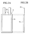
- the unit cell 4 to be assembled into the assembled battery is constituted by a laminate-packed sheet type cell body 4a, and two tabs 4b provided on the right and left ends of the cell body 4a for serving as a positive electrode and a negative electrode, respectively.
- each of unit cell groups 10 is constituted by the two unit cells 4 connected with each other in parallel, and twelve unit cell groups 10 are connected in series by connecting the tabs 4b by the bus bars 5.
- the unit cells 4 are thereby accommodated in the supporter 1 so as to be arranged in four columns by six rows.
- two length types of bus bars 5a and 5b are used as the bus bars 5. Accordingly, it is possible to minimize the size of the assembly battery upon integrating a final assembled battery size.
- FIG. 4A and FIG. 4B are schematic views showing a method of installing the assembled battery according to embodiment 1.
- the tabs 4b of the unit cells 4 and bus bars 5 are joined as larger than the maximum size of the final assembled battery.
- part or all of the joining regions of the joined unit cell groups are folded so as to reduce the entire size of the joined unit cell groups as the final assembled battery size.
- the assembled battery reduced in size is installed in the supporter 1.
- FIG. 4B twelve unit cell groups 10 are arranged and the respective tabs 4b thereof are connected in series by the bus bars 5. Then, the bus bars 5 connecting the third unit cell groups and the fourth unit cell groups from both right and left ends are severally deformed by folding inward as illustrated by arrows in the drawing. In this way, the set of unit cell groups 10 are integrated into the final assembled battery size as shown in FIG. 4A. As the bus bars 5 are connected in the state where the unit cells are unfolded as larger than the maximum size of the final assembled battery, it is possible to secure welding spaces if spot welding or other bonding methods such as ultrasonic vibration welding are used upon connecting the tabs 4b and the bus bars 5. In this way, it is possible to improve productivity.
- spot welding or other bonding methods such as ultrasonic vibration welding
- Embodiment 1 constitutes a circular shape formed by deformation of the bus bars 5b at the same distances from the right and left ends and by connection of the tabs 4 and the bus bars 5. Although it is required to fold two positions of the bus bars 5, the circular shape can obtain resistance against vibration or impact from the outside. Therefore, it is possible to improve the reliability of the assembled battery.
- the thickness of the cell is of several millimeters as in the case of the laminate-packed sheet type cell using a polymer-metal film as a package, it is extremely difficult to connect the tabs 4b and the bus bars 5 after integration as shown in FIG. 4A.
- the bus bars 5 are joined in the unfolded state and then folded for integration, it is possible to join the bus bars easily and to realize the final assembled battery in the compact size.
- the sheet type cells it is possible to secure easiness of deformation from the unfolded state to the integrated state, which is attributed to the thinness of the tabs 4b. As a result, it is possible to form the assembled battery in a compact shape because the cells themselves do not allow wasted spaces.
- a sheet type cell has an outer wall made of a polymer such as nylon, unlike a canned cell including a metallic outer tube. Therefore, the dynamic spring constant of the unit cell is low, meanwhile, efficiency of vibration reduction is high.
- the thickness of the sheet type cell is preferably set within 10 mm so as not to accumulate heat inside the cell. Incidentally, the necessary capacity cannot be obtained from a cell with a thickness of 1 mm or below even if a positive electrode and a negative electrode thereof are made thin. In this context, such a cell does not deem to be economically efficient, but no particular limitation is given.
- FIG. 5A, FIG. 5B and FIG. 5C are views showing a folding part of the bus bar 5.
- both ends of the bus bar 5 may be designed as high bending elasticity regions 50a and a central part thereof may be designed as a low bending elasticity region 50b.
- the bus bar 5 can be bent easily owing to the low bending elasticity region 50b while securing the rigidity of a portion bonding the tab 4b and the bus bar 5.
- the bus bar 5 by a first bus bar 51a, a second bus bar 51b and a supporter 51c for rotatably joining the first bus bar 51a and the second bus bar 51b. It is also possible to join the tab 4b and the bus bar 5 so that a joined part thereof is made rotatable. If the tab 4b and the bus bar 5 are joined rotatably or in a hinged shape, it is easier to deform the unfolded state into the integrated state.
- a laminated composite material formed by the bonding of two types of plastically deformable materials 52a and 52b may be used as the bus bar 5.
- the plastically deformable materials include copper, nickel, aluminum and alloys thereof.
- FIG. 6A, FIG. 6B, FIG. 6C and FIG. 6D are views showing the bus bars 5 having elastically deformable shapes.
- FIG. 6D shows a schematic view of the joining region of the bus bar
- FIG. 6C is an enlarged view of the joining region in FIG. 6D.
- the bus bar 5 may be provided with ridges 53a and troughs 53b and thereby formed as bellows.
- the bus bar 5 may be constituted by spring supporters 54a and a spring 54b. Accordingly, it is possible to deform the unfolded state into the integrated state more easily.
- copper, nickel, aluminum or the like is preferred as the material of these bus bars 5.
- a surface area of the bus bars 5 is preferably in a range from about twice to ten times of a surface area of the tabs 4b.
- the tabs 4b since the tabs 4b generate heat upon the charge or discharge of electricity, it is effective to utilize the bus bars 5 as heat sinks for absorbing the generated heat.
- the bus bars 5 cannot absorb the generated heat adequately if the surface area of the bus bars is less than twice the surface area of the tabs 4b.
- the surface area of the bus bars 5 is larger than ten times the surface area of the tabs 4b, then the aggregate weight of the bus bars 5 is too heavy. In that case, the system constituted by the tabs 4b and the bus bars 5 may be jolted by external vibration. Therefore, there is a risk that durability of the tabs and the like is degraded.
- FIG. 5A, FIG. 5B and FIG. 5C explain the folding part of the bus bar 5, it is needless to say that the bus bars 5 are not the only components to be deformed, but the object of the present invention can be also achieved by folding the tabs 4b instead. Moreover, it is also possible to reduce stress applied to the tabs upon deformation by means of bonding the deformed bus bars 5 to the tabs 4b previously. Furthermore, it is also possible to prepare several types of bus bars of different shapes in advance for connecting the unit cell groups.
- FIG. 7A and FIG. 7B are schematic views showing a method of installing an assembled battery according to embodiment 2.
- tabs 4b of unit cells 4 and bus bars 5 are joined as larger than the maximum size of a final assembled battery.
- part or all of the joining regions of the joined unit cell groups are folded so as to reduce the entire size of the joined unit cell groups into the final assembled battery size.
- the assembled battery reduced in size is installed in the supporter 1. Since the basic constitution is similar to embodiment 1, only different points will be described.
- bus bars 5a and 5b are also used for connection in embodiment 2.
- a positive electrode of a unit cell group 101 which is constituted by unit cells 4 connected in parallel, is connected to a terminal 3, and a negative electrode of the unit cell group 101 is connected to a positive electrode of a unit cell group 102 with the bus bar 5b.
- a negative electrode of the unit cell group 102 is connected to a positive electrode of a unit cell group 103 with the bus bar 5a.
- the bus bars 5b are folded severally in directions as illustrated with arrows in FIG. 7B, so that the unit cell groups are integrated and formed into the final assembled battery size as shown in FIG. 7A. Thereafter, the assembled battery reduced in size is installed inside the supporter 1. In this event, six pieces of the bus bars 5b are folded. Accordingly, it is possible to obtain operational effects similar to embodiment 1.
- FIG. 8A, FIG. 8B and FIG. 8C are schematic views showing a method of installing an assembled battery according to embodiment 3.
- tabs 4b of unit cells 4 and bus bars 5 are joined as larger than the maximum size of a final assembled battery.
- part or all of the joining regions of the joined unit cell groups are folded so as to reduce the entire size of the joined unit cell groups into the final assembled battery size.
- the assembled battery reduced in size is installed in the supporter 1. Since the basic constitution is similar to embodiment 1, only different points will be described.
- one type of bus bar 5 is used for connection in embodiment 3.
- a positive electrode of a unit cell group 201 which is constituted by unit cells 4 connected in parallel, is connected to a terminal 3, and a negative electrode of the unit cell group 201 is connected to a positive electrode of a unit cell group 202 with the bus bar 5.
- a negative electrode of the unit cell group 202 is connected to a positive electrode of a unit cell group 203 with the bus bar 5.
- the bus bars 5 are folded severally in directions as illustrated with arrows in FIG. 8B, so that the unit cell groups are integrated and formed into the final assembled battery size as shown in FIG. 8A. Thereafter, the assembled battery reduced in size is installed inside the supporter 1. In this event, eleven pieces of the bus bars 5 are folded. In this way, it is possible to obtain operational effects similar to embodiments 1 and 2.
- FIG. 9A and FIG. 9B are schematic views showing a method of installing an assembled battery according to embodiment 4.
- tabs 4b of unit cells 4 and bus bars 5 are joined as larger than the maximum size of a final assembled battery.
- part or all of the joining regions of the joined unit cell groups are folded so as to reduce the entire size of the joined unit cell groups into the final assembled battery size.
- the assembled battery reduced in size is installed in the supporter 1. Since the basic constitution is similar to embodiment 1, only different points will be described.
- bus bars 5a and 5b are used for connection in embodiment 4.
- a negative electrode of a unit cell group 301 which is constituted by unit cells 4 connected in parallel, is connected to a terminal 3, and unit cell groups 301, 302, 303, 304, 305 and a negative electrode of the unit cell group 306 are connected in series with the bus bars 5a.
- a positive electrode of the unit cell group 306 is connected to a negative electrode of a unit cell group 307 with the bus bar 5b.
- a positive electrode of the unit cell group 307 and unit cell groups 308, 309, 310, 311 and 312 are connected in series with the bus bars 5a.
- the bus bar 5b is folded in a direction as illustrated with an arrows in FIG. 9B, so that the unit cell groups are integrated and formed into the final assembled battery size as shown in FIG. 9A. Thereafter, the assembled battery reduced in size is installed inside the supporter 1. In this event, one piece of the bus bar 5b is folded. In this way, it is possible to obtain operational effects similar to embodiments 1 to 3. Moreover, it is also possible to improve productivity because the bus bars 5 which are subject to folding are minimized.
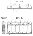
- FIG. 10A is a top plan view showing an assembled battery of embodiment 5
- FIG. 10B is an end view showing the same
- FIG. 10C is a sectional view taken along a line XC-XC in FIG. 10A. Since the basic constitution is similar to that of embodiment 1, only different points will be described.
- Reference numeral 8 denotes a laminate-packed unit cell. As shown in Fig. 11A and Fig. 11B, each of the unit cells 8 is constituted by a laminate-packed sheet type cell body 8a, and two tabs 8b provided on front and back ends of the cell body 8a to serve as a positive electrode and a negative electrode, respectively. As shown in schematic perspective views of the assembled battery in FIG. 12A and FIG.
- each of unit cell groups 11 is constituted by the two unit cells 8 connected with each other in parallel, and twelve unit cell groups 11 are connected in series by connecting the tabs 8b by means of bus bars 5 (5c and 5d).
- the unit cells 8 are thereby accommodated in the supporter 1 so as to be arranged in four columns by six rows.
- FIG. 13A and FIG. 13B are schematic views showing a method of installing the assembled battery according to embodiment 5.
- tabs 8b of the unit cells 8 and the bus bars 5 are joined as larger than the maximum size of a final assembled battery.
- part or all of the joining regions of the joined unit cell groups are folded so as to reduce the entire size of the joined unit cell groups into the final assembled battery size.
- the assembled battery reduced in size is installed in the supporter 1.
- the unit cell groups are arranged in parallel in two rows each including six unit cell groups (the row including unit cell groups 401, 404, 405, 408, 409 and 412, and the row including unit cell groups 402, 403, 406, 407, 410 and 411), and the respective tabs 8b are connected in series with the bus bars 5c.
- a positive electrode of the unit cell group 401 is connected to the terminal 3 and a negative electrode of the unit cell group 402 is connected to a positive electrode of the unit cell group 403 with the bus bar 5d. Similar connection is performed regarding other unit cell groups.
- the bus bars 5c located between the two rows in FIG. 13B are severally deformed so that the two rows are overlapped by folding. Accordingly, the unit cell groups are integrated into the final assembled battery size as shown in FIG. 13A. In this way, it is possible to obtain operational effects similar to embodiment 1.
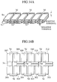
- FIG. 14A and FIG. 14B are schematic views showing a method of installing an assembled battery according to embodiment 6.
- tabs 8b of unit cells 8 and bus bars 5 are joined as larger than the maximum size of a final assembled battery.
- part or all of the joining regions of the joined unit cell groups are folded so as to reduce the entire size of the joined unit cell groups into the final assembled battery size.
- the assembled battery reduced in size is installed in the supporter 1. Since the basic constitution is similar to embodiment 5, only different points will be described.
- the unit cell groups are arranged in parallel in two rows each including six unit cell groups (the row including unit cell groups 501, 502, 503, 504, 505 and 506, and the row including unit cell groups 507, 508, 509, 510, 511 and 512), and the respective tabs 8b are connected in series by means of the bus bars 5d.
- a positive electrode of the unit cell group 506 is connected to a negative electrode of the unit cell group 507 by the bus bar 5c.
- the bus bar 5c located between the two rows in FIG. 14B is deformed so that the two rows are overlapped by folding. Accordingly, the unit cell groups are integrated into the final assembled battery size as shown in FIG. 14A. In this way, it is possible to obtain operational effects similar to embodiment 1.
- the tabs of the unit cells and the bus bars are first joined as larger than the maximum size of a final assembled battery. Then, part or all of the joining regions of the joined unit cell groups are folded by deforming the tabs or the bus bars in the maximum length direction, in other words, along the longest unit cell group. Accordingly, the entire size of the joined unit cell groups is reduced into the final assembled battery size and the assembled battery is installed in the outer case. In this way, it is possible to obtain the operational effects as described above.
- the assembled battery can be fabricated by joining all the unit cells in an unfolded slate outside an outer case of the assembled battery, then by compactly deforming the set of the unit cells from a joined state into an integrated state, by inserting the set of the unit cells into the outer case of the assembled battery and by connecting the terminals and the like. According to the above-described installing method, it is possible to fabricate the assembled battery by joining easily thin unit cells, which has been particularly difficult to achieve in the prior art.
- the assembled battery of the present invention can secure sufficient vibration resistance, shock resistance and heat resistance. Therefore, the assembled battery can be adapted effectively to an automobile.
- An assembled battery in an integrated state as shown in FIG. 4A was fabricated by using a constitution similar to the constitution described in embodiment 1 and by folding the bus bars in two positions.
- Such a structure of the assembled battery is referred to as a joint structure 1.
- the size in the unfolded state thereof was set twice as large as the size at the final stage of the assembled battery having the joint structure 1.
- Plastically deformable copper was used for the bus bars.
- An assembled battery in an integrated state as shown in FIG. 7A was fabricated by using a constitution similar to the constitution described in embodiment 2 and by folding the bus bars in six positions.
- Such a structure of the assembled battery is referred to as a joint structure 2.
- the size in the unfolded state thereof was set one and a half time as large as the size at the final stage of the assembled battery having the joint structure 2.
- Plastically deformable copper was used for the bus bars.
- An assembled battery in an integrated state as shown in FIG. 8A was fabricated by using a constitution similar to the constitution described in embodiment 3 and by folding the bus bars in eleven positions.
- Such a structure of the assembled battery is referred to as a joint structure 3.
- the size in the unfolded state thereof was set 1.3 limes as large as the size at the final stage of the assembled battery having the joint structure 3.
- Plastically deformable copper was used for the bus bars.
- An assembled battery in an integrated state as shown in FIG. 9A was fabricated by using a constitution similar to the constitution described in embodiment 4 and by folding the bus bars in one position.
- Such a structure of the assembled battery is referred to as a joint structure 4.
- the size in the unfolded state thereof was set twice as large as the size at the final stage of the assembled battery having the joint structure 4.
- Plastically deformable copper was used for the bus bars.
- An assembled battery in an integrated state as shown in FIG. 13A was fabricated by using a constitution similar to the constitution described in embodiment 5 and by folding the bus bars in six positions.
- Such a structure of the assembled battery is referred to as a joint structure 5.
- the size in the unfolded state thereof was set twice as large as the size at the final stage of the assembled battery having the joint structure 5.
- Plastically deformable copper was used for the bus bars.
- An assembled battery in an integrated state as shown in FIG. 14A was fabricated by using a constitution similar to the constitution described in embodiment 6 and by folding the bus bars in one position.
- Such a structure of the assembled battery is referred to as a joint structure 6.
- the size in the unfolded state thereof was set twice as large as the size at the final stage of the assembled battery having the joint structure 6.
- Plastically deformable copper was used for the bus bars.
- An assembled battery was fabricated as identical to embodiment 4, except that the bus bars were made rotatably as shown in FIG. 5B.
- An assembled battery was fabricated as identical to embodiment 5, except that the bus bars were made of a composite material as shown in FIG. 5A having a different bending elasticity in the central part thereof.
- bus bars were made of a composite material of copper and nickel as shown in FIG. 5C.
- Fabrication of an assembled battery having a joint structure 3 was attempted by use of thin laminate cells. First, all unit cells were integrated into a final state and ultrasonic welding was attempted to connect bus bars and tabs of the respective unit cells. However, it was impossible to connect the bus bars and the tabs because welding spaces were not obtained.
Landscapes
- Chemical & Material Sciences (AREA)
- Chemical Kinetics & Catalysis (AREA)
- Electrochemistry (AREA)
- General Chemical & Material Sciences (AREA)
- Inorganic Chemistry (AREA)
- Connection Of Batteries Or Terminals (AREA)
- Battery Mounting, Suspending (AREA)
Applications Claiming Priority (2)
| Application Number | Priority Date | Filing Date | Title |
|---|---|---|---|
| JP2001348755 | 2001-11-14 | ||
| JP2001348755A JP2003151526A (ja) | 2001-11-14 | 2001-11-14 | 組電池及びその設置方法 |
Publications (1)
| Publication Number | Publication Date |
|---|---|
| EP1313156A2 true EP1313156A2 (de) | 2003-05-21 |
Family
ID=19161532
Family Applications (1)
| Application Number | Title | Priority Date | Filing Date |
|---|---|---|---|
| EP02023208A Withdrawn EP1313156A2 (de) | 2001-11-14 | 2002-10-16 | Zusammengesetzte Batterie |
Country Status (3)
| Country | Link |
|---|---|
| US (1) | US20030091896A1 (de) |
| EP (1) | EP1313156A2 (de) |
| JP (1) | JP2003151526A (de) |
Cited By (6)
| Publication number | Priority date | Publication date | Assignee | Title |
|---|---|---|---|---|
| WO2004114441A3 (en) * | 2003-06-18 | 2005-11-03 | Nissan Motor | Method of manufacturing secondary battery electrode, apparatus for manufacturing the same and secondary battery electrode |
| WO2010142679A1 (de) * | 2009-06-08 | 2010-12-16 | Auto-Kabel Managementgesellschaft Mbh | Batteriezellenverbinder |
| EP2410590A3 (de) * | 2009-12-24 | 2012-05-30 | Sanyo Electric Co., Ltd. | Batteriepack |
| EP2109906B1 (de) * | 2007-02-09 | 2016-09-07 | Johnson Controls Advanced Power Solutions LLC | Sammelschiene für batterien |
| WO2019063438A1 (de) * | 2017-09-29 | 2019-04-04 | Elringklinger Ag | Zellverbinder für eine elektrochemische vorrichtung |
| EP4109651A4 (de) * | 2020-02-18 | 2024-11-20 | BYD Company Limited | Batterie, batteriemodul, batteriepack und elektrofahrzeug |
Families Citing this family (53)
| Publication number | Priority date | Publication date | Assignee | Title |
|---|---|---|---|---|
| US7198866B2 (en) * | 2002-07-09 | 2007-04-03 | Nissan Motor Co., Ltd. | Cell assembly |
| JP4539051B2 (ja) * | 2003-08-04 | 2010-09-08 | 日産自動車株式会社 | リチウム二次電池 |
| JP4186781B2 (ja) * | 2003-10-10 | 2008-11-26 | 日産自動車株式会社 | 組電池 |
| EP2352185A1 (de) * | 2003-10-28 | 2011-08-03 | Johnson Controls Techonology Company | Batterieummantelung mit verbesserter Wärmeverteilung |
| JP2006236828A (ja) * | 2005-02-25 | 2006-09-07 | Toyota Motor Corp | 電池モジュール |
| JP5105390B2 (ja) * | 2005-03-09 | 2012-12-26 | 日立ビークルエナジー株式会社 | 大電流放電用薄形二次電池及び電池モジュール |
| CN101395781B (zh) | 2005-03-16 | 2011-09-14 | 福特全球技术公司 | 电源温度传感器和系统 |
| CA2600595C (en) * | 2005-03-16 | 2013-07-23 | Ford Global Technologies, Llc | Power supply system |
| US7604896B2 (en) * | 2005-03-16 | 2009-10-20 | Ford Global Technologies, Llc | High voltage battery assembly for a motor vehicle |
| US8728666B2 (en) | 2005-04-28 | 2014-05-20 | Nissan Motor Co., Ltd. | Positive electrode material for lithium ion battery with nonaqueous electrolyte, and battery using the same |
| JP2007280907A (ja) * | 2006-04-12 | 2007-10-25 | Seiko Epson Corp | 電極の製造方法、電極の製造装置、および二次電池の製造方法 |
| JP2007307547A (ja) * | 2006-04-17 | 2007-11-29 | Seiko Epson Corp | 機能膜の形成方法、電極の製造方法および二次電池の製造方法 |
| JP2008016202A (ja) * | 2006-07-03 | 2008-01-24 | Hitachi Maxell Ltd | ラミネート外装扁平形電池の電池モジュール |
| JP5159233B2 (ja) * | 2007-09-28 | 2013-03-06 | 株式会社東芝 | バスバー |
| WO2009041735A1 (en) * | 2007-09-27 | 2009-04-02 | Kabushiki Kaisha Toshiba | Bus bar |
| JP2009164468A (ja) * | 2008-01-09 | 2009-07-23 | Nissin Electric Co Ltd | 電気二重層コンデンサモジュール |
| DE102008034871A1 (de) * | 2008-07-26 | 2010-01-28 | Daimler Ag | Batterie, insbesondere Fahrzeugbatterie |
| DE102008035169B3 (de) * | 2008-07-28 | 2010-01-21 | Amphenol-Tuchel Electronics Gmbh | Elektrischer Leiter für Energiespeicher |
| US9028986B2 (en) | 2009-01-07 | 2015-05-12 | A123 Systems Llc | Fuse for battery cells |
| US8257848B2 (en) | 2009-01-12 | 2012-09-04 | A123 Systems, Inc. | Safety venting mechanism with tearing tooth structure for batteries |
| JP2010277726A (ja) | 2009-05-26 | 2010-12-09 | Jst Mfg Co Ltd | バッテリ用コネクタ |
| DE102009050316A1 (de) | 2009-10-16 | 2011-04-21 | Elringklinger Ag | Zellverbinder |
| KR101146677B1 (ko) * | 2009-10-30 | 2012-05-22 | 에스비리모티브 주식회사 | 버스바홀더 |
| US20110117408A1 (en) * | 2009-11-13 | 2011-05-19 | Lennox Stuart B | Battery Assembly |
| CN202978302U (zh) | 2009-12-04 | 2013-06-05 | A123系统公司 | 具有集成的电源管理系统和可伸缩电池断路组件的电池系统 |
| US9537173B2 (en) * | 2010-02-10 | 2017-01-03 | Lg Chem, Ltd. | Pouch type lithium secondary battery |
| US20120000964A1 (en) * | 2010-07-01 | 2012-01-05 | Gm Global Technology Operations, Inc. | Battery tab joints and methods of making |
| DE102010034686A1 (de) * | 2010-08-18 | 2012-02-23 | Volkswagen Ag | Kontaktelement und Batterieeinheit |
| CN202495505U (zh) | 2011-11-25 | 2012-10-17 | 深圳市比亚迪锂电池有限公司 | 一种电连接件以及一种电池 |
| CN103296241A (zh) * | 2012-03-02 | 2013-09-11 | 深圳市比亚迪锂电池有限公司 | 一种电连接件以及一种电池 |
| KR101627631B1 (ko) * | 2012-04-12 | 2016-06-07 | 삼성에스디아이 주식회사 | 이차 전지 및 그 모듈 |
| JP6153798B2 (ja) | 2013-05-23 | 2017-06-28 | Connexx Systems株式会社 | 板状組電池およびこれらを複数個組み合わせて構成される板状組電池群 |
| WO2016004079A1 (en) | 2014-06-30 | 2016-01-07 | Black & Decker Inc. | Battery pack for a cordless power tools |
| US9478779B2 (en) * | 2014-08-20 | 2016-10-25 | Ford Global Technologies, Llc | Cell to cell terminal connections for a high voltage battery |
| US10418664B2 (en) * | 2014-09-26 | 2019-09-17 | Arizona Board Of Regents On Behalf Of Arizona State University | Stretchable batteries |
| JP6394964B2 (ja) * | 2014-12-22 | 2018-09-26 | 株式会社オートネットワーク技術研究所 | 蓄電モジュール |
| CN107431059B (zh) | 2015-01-02 | 2020-03-17 | 亚利桑那州立大学董事会 | 用于可变形电子装置的阿基米德螺线设计 |
| DE102015210631A1 (de) * | 2015-06-10 | 2016-12-15 | Robert Bosch Gmbh | Batteriezelle und Verfahren zum Verbinden von Batteriezellen sowie Batteriepack, Batteriemodul, Batterie und Fahrzeug |
| US10135208B2 (en) | 2017-01-25 | 2018-11-20 | Ford Global Technologies, Llc | Hinged low profile modular electrical power bar for a vehicle |
| JP6645999B2 (ja) * | 2017-03-21 | 2020-02-14 | 株式会社東芝 | 二次電池、電池パック、及び車両 |
| US10573870B2 (en) | 2017-08-11 | 2020-02-25 | Cora Aero Llc | Series batteries to reduce an interfering magnetic field |
| WO2019132155A1 (ko) * | 2017-12-28 | 2019-07-04 | 삼성에스디아이 주식회사 | 전지 모듈 |
| EP3506383B1 (de) * | 2017-12-28 | 2020-02-12 | Samsung SDI Co., Ltd. | Batteriemodul |
| US10811799B2 (en) * | 2018-02-09 | 2020-10-20 | Metrospec Technology, L.L.C. | Interconnectable circuit boards adapted for lateral in-plane bending |
| KR102404239B1 (ko) * | 2018-09-10 | 2022-05-30 | 주식회사 엘지에너지솔루션 | Icb 조립체, 이를 포함한 배터리 모듈 및 그 제조 방법 |
| KR102393936B1 (ko) * | 2018-09-10 | 2022-05-03 | 주식회사 엘지에너지솔루션 | Icb 조립체, 이를 포함한 배터리 모듈 및 그 제조 방법 |
| KR102309630B1 (ko) * | 2018-09-10 | 2021-10-05 | 주식회사 엘지에너지솔루션 | Icb 조립체, 이를 포함한 배터리 모듈 및 그 제조 방법 |
| JP7172728B2 (ja) * | 2019-02-27 | 2022-11-16 | トヨタ自動車株式会社 | 電池パック |
| US12016121B2 (en) | 2020-10-23 | 2024-06-18 | Metrospec Technology, L.L.C. | Interconnectable circuit boards adapted for three-dimensional constructions as lighting sources |
| US11791515B2 (en) | 2021-08-18 | 2023-10-17 | Beta Air, Llc | Battery assembly for an aircraft |
| US12088077B1 (en) | 2021-12-29 | 2024-09-10 | Beta Air, Llc | Systems and methods for laminated buswork with flexible conductors for an electric aircraft |
| JP7593959B2 (ja) * | 2022-02-04 | 2024-12-03 | プライムプラネットエナジー&ソリューションズ株式会社 | 電池パック |
| DE102024209375A1 (de) * | 2024-09-27 | 2026-04-02 | Volkswagen Aktiengesellschaft | Batteriestack mit durch mindestens ein Kontaktelement verbundenen Batteriezellen |
-
2001
- 2001-11-14 JP JP2001348755A patent/JP2003151526A/ja active Pending
-
2002
- 2002-10-16 EP EP02023208A patent/EP1313156A2/de not_active Withdrawn
- 2002-11-01 US US10/285,622 patent/US20030091896A1/en not_active Abandoned
Cited By (8)
| Publication number | Priority date | Publication date | Assignee | Title |
|---|---|---|---|---|
| WO2004114441A3 (en) * | 2003-06-18 | 2005-11-03 | Nissan Motor | Method of manufacturing secondary battery electrode, apparatus for manufacturing the same and secondary battery electrode |
| EP2109906B1 (de) * | 2007-02-09 | 2016-09-07 | Johnson Controls Advanced Power Solutions LLC | Sammelschiene für batterien |
| WO2010142679A1 (de) * | 2009-06-08 | 2010-12-16 | Auto-Kabel Managementgesellschaft Mbh | Batteriezellenverbinder |
| US8574008B2 (en) | 2009-06-08 | 2013-11-05 | Bayerische Motoren Werke | Battery cell connector |
| EP2410590A3 (de) * | 2009-12-24 | 2012-05-30 | Sanyo Electric Co., Ltd. | Batteriepack |
| EP2500960A1 (de) * | 2009-12-24 | 2012-09-19 | Sanyo Electric Co., Ltd. | Zylindrisches Batteriepack |
| WO2019063438A1 (de) * | 2017-09-29 | 2019-04-04 | Elringklinger Ag | Zellverbinder für eine elektrochemische vorrichtung |
| EP4109651A4 (de) * | 2020-02-18 | 2024-11-20 | BYD Company Limited | Batterie, batteriemodul, batteriepack und elektrofahrzeug |
Also Published As
| Publication number | Publication date |
|---|---|
| US20030091896A1 (en) | 2003-05-15 |
| JP2003151526A (ja) | 2003-05-23 |
Similar Documents
| Publication | Publication Date | Title |
|---|---|---|
| EP1313156A2 (de) | Zusammengesetzte Batterie | |
| JP5323782B2 (ja) | 電池モジュール及び複数の電池モジュールを備える電池パック | |
| EP2738838B1 (de) | Batteriemodul mit erhöhter zuverlässigkeit und mittlere bis grosse batteriepackung damit | |
| KR100637443B1 (ko) | 이차 전지와 이에 사용되는 단자 조립체 | |
| CN102754240B (zh) | 改进焊接可靠性的电池模块和使用该电池模块的电池组 | |
| US7790311B2 (en) | Rechargeable battery having lead terminal extending along at least half of a circumference of an electrode assembly | |
| JP4772614B2 (ja) | 電池モジュール | |
| JP5932997B2 (ja) | 連結信頼性の向上した電池モジュール及びこれを備えた中大型電池パック | |
| CN108475742B (zh) | 包括以卡接式连接部件接合的外壳部件的电池模组 | |
| JP6520097B2 (ja) | 蓄電素子 | |
| EP2528131B1 (de) | Elektrische Speichervorrichtung und Isolationsabdeckung | |
| JP7348270B2 (ja) | 電源装置と電源装置を備える電動車両及び蓄電装置 | |
| JP6620944B2 (ja) | 直列接続用のラミネート型電池、及び組電池 | |
| CN102005557A (zh) | 用于电池模块的单元凸片连结 | |
| US20220123415A1 (en) | Method for Manufacturing Battery Module | |
| KR100627360B1 (ko) | 집전판용 플레이트와 이의 이차 전지 및 전지 모듈 | |
| JP7753555B2 (ja) | バッテリーモジュール、当該バッテリーモジュールを含むバッテリーパック及び自動車 | |
| JP7481325B2 (ja) | 電源装置及びこれを用いた電動車両並びに蓄電装置、電源装置用締結部材、電源装置の製造方法、電源装置用締結部材の製造方法 | |
| KR20090000297A (ko) | 플레이트형 보강부재를 포함하고 있는 장치 | |
| EP4123674A1 (de) | Energiespeichervorrichtung | |
| JP7762871B2 (ja) | 蓄電モジュール | |
| CN212783703U (zh) | 电池单体、电池以及用电装置 | |
| JP2022026171A (ja) | 蓄電モジュール、ならびに溶接方法およびそれを用いた蓄電モジュールの製造方法 | |
| JP7800999B2 (ja) | 上下端分離型バスバーフレームを含むバッテリーモジュールおよびこれを組み立てる方法 | |
| JP7544497B2 (ja) | 組電池 |
Legal Events
| Date | Code | Title | Description |
|---|---|---|---|
| PUAI | Public reference made under article 153(3) epc to a published international application that has entered the european phase |
Free format text: ORIGINAL CODE: 0009012 |
|
| 17P | Request for examination filed |
Effective date: 20021016 |
|
| AK | Designated contracting states |
Designated state(s): AT BE BG CH CY CZ DE DK EE ES FI FR GB GR IE IT LI LU MC NL PT SE SK TR |
|
| AX | Request for extension of the european patent |
Extension state: AL LT LV MK RO SI |
|
| STAA | Information on the status of an ep patent application or granted ep patent |
Free format text: STATUS: THE APPLICATION HAS BEEN WITHDRAWN |
|
| 18W | Application withdrawn |
Effective date: 20040930 |