EP1314406A2 - Einsatz für einen Kanal - Google Patents
Einsatz für einen Kanal Download PDFInfo
- Publication number
- EP1314406A2 EP1314406A2 EP02258031A EP02258031A EP1314406A2 EP 1314406 A2 EP1314406 A2 EP 1314406A2 EP 02258031 A EP02258031 A EP 02258031A EP 02258031 A EP02258031 A EP 02258031A EP 1314406 A2 EP1314406 A2 EP 1314406A2
- Authority
- EP
- European Patent Office
- Prior art keywords
- insert
- stent
- longitudinally extending
- helix
- extending member
- Prior art date
- Legal status (The legal status is an assumption and is not a legal conclusion. Google has not performed a legal analysis and makes no representation as to the accuracy of the status listed.)
- Granted
Links
- 230000000694 effects Effects 0.000 claims abstract description 4
- 239000000463 material Substances 0.000 claims description 18
- 210000001367 artery Anatomy 0.000 claims description 15
- 241001465754 Metazoa Species 0.000 claims description 9
- 210000003462 vein Anatomy 0.000 claims description 6
- 239000000560 biocompatible material Substances 0.000 claims description 4
- 230000015572 biosynthetic process Effects 0.000 abstract description 6
- 210000001715 carotid artery Anatomy 0.000 description 16
- 230000017531 blood circulation Effects 0.000 description 7
- 210000004204 blood vessel Anatomy 0.000 description 6
- 239000008280 blood Substances 0.000 description 5
- 210000004369 blood Anatomy 0.000 description 5
- 238000005755 formation reaction Methods 0.000 description 5
- 238000003780 insertion Methods 0.000 description 3
- 230000037431 insertion Effects 0.000 description 3
- 239000004814 polyurethane Substances 0.000 description 3
- 229920002635 polyurethane Polymers 0.000 description 3
- 208000031481 Pathologic Constriction Diseases 0.000 description 2
- 206010072810 Vascular wall hypertrophy Diseases 0.000 description 2
- 230000008901 benefit Effects 0.000 description 2
- 230000005489 elastic deformation Effects 0.000 description 2
- 239000006261 foam material Substances 0.000 description 2
- 230000036262 stenosis Effects 0.000 description 2
- 208000037804 stenosis Diseases 0.000 description 2
- 229920005830 Polyurethane Foam Polymers 0.000 description 1
- 239000000853 adhesive Substances 0.000 description 1
- 230000001070 adhesive effect Effects 0.000 description 1
- 238000002583 angiography Methods 0.000 description 1
- 230000009286 beneficial effect Effects 0.000 description 1
- 238000001816 cooling Methods 0.000 description 1
- 238000010586 diagram Methods 0.000 description 1
- 238000000502 dialysis Methods 0.000 description 1
- 230000002349 favourable effect Effects 0.000 description 1
- 239000012530 fluid Substances 0.000 description 1
- -1 for example Substances 0.000 description 1
- 239000003292 glue Substances 0.000 description 1
- 230000001939 inductive effect Effects 0.000 description 1
- 238000002347 injection Methods 0.000 description 1
- 239000007924 injection Substances 0.000 description 1
- 238000001746 injection moulding Methods 0.000 description 1
- 238000001361 intraarterial administration Methods 0.000 description 1
- 238000002844 melting Methods 0.000 description 1
- 230000008018 melting Effects 0.000 description 1
- 239000012528 membrane Substances 0.000 description 1
- 238000000465 moulding Methods 0.000 description 1
- 230000007505 plaque formation Effects 0.000 description 1
- 239000004033 plastic Substances 0.000 description 1
- 229920003023 plastic Polymers 0.000 description 1
- 229920000728 polyester Polymers 0.000 description 1
- 239000004810 polytetrafluoroethylene Substances 0.000 description 1
- 229920001343 polytetrafluoroethylene Polymers 0.000 description 1
- 239000011496 polyurethane foam Substances 0.000 description 1
- 238000005086 pumping Methods 0.000 description 1
- 230000025033 vasoconstriction Effects 0.000 description 1
Images


Classifications
-
- A—HUMAN NECESSITIES
- A61—MEDICAL OR VETERINARY SCIENCE; HYGIENE
- A61F—FILTERS IMPLANTABLE INTO BLOOD VESSELS; PROSTHESES; DEVICES PROVIDING PATENCY TO, OR PREVENTING COLLAPSING OF, TUBULAR STRUCTURES OF THE BODY, e.g. STENTS; ORTHOPAEDIC, NURSING OR CONTRACEPTIVE DEVICES; FOMENTATION; TREATMENT OR PROTECTION OF EYES OR EARS; BANDAGES, DRESSINGS OR ABSORBENT PADS; FIRST-AID KITS
- A61F2/00—Filters implantable into blood vessels; Prostheses, i.e. artificial substitutes or replacements for parts of the body; Appliances for connecting them with the body; Devices providing patency to, or preventing collapsing of, tubular structures of the body, e.g. stents
- A61F2/82—Devices providing patency to, or preventing collapsing of, tubular structures of the body, e.g. stents
- A61F2/86—Stents in a form characterised by the wire-like elements; Stents in the form characterised by a net-like or mesh-like structure
- A61F2/90—Stents in a form characterised by the wire-like elements; Stents in the form characterised by a net-like or mesh-like structure characterised by a net-like or mesh-like structure
-
- A—HUMAN NECESSITIES
- A61—MEDICAL OR VETERINARY SCIENCE; HYGIENE
- A61F—FILTERS IMPLANTABLE INTO BLOOD VESSELS; PROSTHESES; DEVICES PROVIDING PATENCY TO, OR PREVENTING COLLAPSING OF, TUBULAR STRUCTURES OF THE BODY, e.g. STENTS; ORTHOPAEDIC, NURSING OR CONTRACEPTIVE DEVICES; FOMENTATION; TREATMENT OR PROTECTION OF EYES OR EARS; BANDAGES, DRESSINGS OR ABSORBENT PADS; FIRST-AID KITS
- A61F2/00—Filters implantable into blood vessels; Prostheses, i.e. artificial substitutes or replacements for parts of the body; Appliances for connecting them with the body; Devices providing patency to, or preventing collapsing of, tubular structures of the body, e.g. stents
- A61F2/02—Prostheses implantable into the body
- A61F2/04—Hollow or tubular parts of organs, e.g. bladders, tracheae, bronchi or bile ducts
- A61F2/06—Blood vessels
-
- F—MECHANICAL ENGINEERING; LIGHTING; HEATING; WEAPONS; BLASTING
- F15—FLUID-PRESSURE ACTUATORS; HYDRAULICS OR PNEUMATICS IN GENERAL
- F15D—FLUID DYNAMICS, i.e. METHODS OR MEANS FOR INFLUENCING THE FLOW OF GASES OR LIQUIDS
- F15D1/00—Influencing flow of fluids
- F15D1/02—Influencing flow of fluids in pipes or conduits
- F15D1/04—Arrangements of guide vanes in pipe elbows or duct bends; Construction of pipe conduit elements for elbows with respect to flow, e.g. for reducing losses of flow
-
- A—HUMAN NECESSITIES
- A61—MEDICAL OR VETERINARY SCIENCE; HYGIENE
- A61F—FILTERS IMPLANTABLE INTO BLOOD VESSELS; PROSTHESES; DEVICES PROVIDING PATENCY TO, OR PREVENTING COLLAPSING OF, TUBULAR STRUCTURES OF THE BODY, e.g. STENTS; ORTHOPAEDIC, NURSING OR CONTRACEPTIVE DEVICES; FOMENTATION; TREATMENT OR PROTECTION OF EYES OR EARS; BANDAGES, DRESSINGS OR ABSORBENT PADS; FIRST-AID KITS
- A61F2/00—Filters implantable into blood vessels; Prostheses, i.e. artificial substitutes or replacements for parts of the body; Appliances for connecting them with the body; Devices providing patency to, or preventing collapsing of, tubular structures of the body, e.g. stents
- A61F2/82—Devices providing patency to, or preventing collapsing of, tubular structures of the body, e.g. stents
- A61F2/86—Stents in a form characterised by the wire-like elements; Stents in the form characterised by a net-like or mesh-like structure
- A61F2/90—Stents in a form characterised by the wire-like elements; Stents in the form characterised by a net-like or mesh-like structure characterised by a net-like or mesh-like structure
- A61F2/91—Stents in a form characterised by the wire-like elements; Stents in the form characterised by a net-like or mesh-like structure characterised by a net-like or mesh-like structure made from perforated sheets or tubes, e.g. perforated by laser cuts or etched holes
-
- A—HUMAN NECESSITIES
- A61—MEDICAL OR VETERINARY SCIENCE; HYGIENE
- A61F—FILTERS IMPLANTABLE INTO BLOOD VESSELS; PROSTHESES; DEVICES PROVIDING PATENCY TO, OR PREVENTING COLLAPSING OF, TUBULAR STRUCTURES OF THE BODY, e.g. STENTS; ORTHOPAEDIC, NURSING OR CONTRACEPTIVE DEVICES; FOMENTATION; TREATMENT OR PROTECTION OF EYES OR EARS; BANDAGES, DRESSINGS OR ABSORBENT PADS; FIRST-AID KITS
- A61F2/00—Filters implantable into blood vessels; Prostheses, i.e. artificial substitutes or replacements for parts of the body; Appliances for connecting them with the body; Devices providing patency to, or preventing collapsing of, tubular structures of the body, e.g. stents
- A61F2/02—Prostheses implantable into the body
- A61F2/04—Hollow or tubular parts of organs, e.g. bladders, tracheae, bronchi or bile ducts
- A61F2/06—Blood vessels
- A61F2002/068—Modifying the blood flow model, e.g. by diffuser or deflector
-
- A—HUMAN NECESSITIES
- A61—MEDICAL OR VETERINARY SCIENCE; HYGIENE
- A61F—FILTERS IMPLANTABLE INTO BLOOD VESSELS; PROSTHESES; DEVICES PROVIDING PATENCY TO, OR PREVENTING COLLAPSING OF, TUBULAR STRUCTURES OF THE BODY, e.g. STENTS; ORTHOPAEDIC, NURSING OR CONTRACEPTIVE DEVICES; FOMENTATION; TREATMENT OR PROTECTION OF EYES OR EARS; BANDAGES, DRESSINGS OR ABSORBENT PADS; FIRST-AID KITS
- A61F2210/00—Particular material properties of prostheses classified in groups A61F2/00 - A61F2/26 or A61F2/82 or A61F9/00 or A61F11/00 or subgroups thereof
- A61F2210/0004—Particular material properties of prostheses classified in groups A61F2/00 - A61F2/26 or A61F2/82 or A61F9/00 or A61F11/00 or subgroups thereof bioabsorbable
-
- A—HUMAN NECESSITIES
- A61—MEDICAL OR VETERINARY SCIENCE; HYGIENE
- A61F—FILTERS IMPLANTABLE INTO BLOOD VESSELS; PROSTHESES; DEVICES PROVIDING PATENCY TO, OR PREVENTING COLLAPSING OF, TUBULAR STRUCTURES OF THE BODY, e.g. STENTS; ORTHOPAEDIC, NURSING OR CONTRACEPTIVE DEVICES; FOMENTATION; TREATMENT OR PROTECTION OF EYES OR EARS; BANDAGES, DRESSINGS OR ABSORBENT PADS; FIRST-AID KITS
- A61F2220/00—Fixations or connections for prostheses classified in groups A61F2/00 - A61F2/26 or A61F2/82 or A61F9/00 or A61F11/00 or subgroups thereof
- A61F2220/0008—Fixation appliances for connecting prostheses to the body
-
- A—HUMAN NECESSITIES
- A61—MEDICAL OR VETERINARY SCIENCE; HYGIENE
- A61F—FILTERS IMPLANTABLE INTO BLOOD VESSELS; PROSTHESES; DEVICES PROVIDING PATENCY TO, OR PREVENTING COLLAPSING OF, TUBULAR STRUCTURES OF THE BODY, e.g. STENTS; ORTHOPAEDIC, NURSING OR CONTRACEPTIVE DEVICES; FOMENTATION; TREATMENT OR PROTECTION OF EYES OR EARS; BANDAGES, DRESSINGS OR ABSORBENT PADS; FIRST-AID KITS
- A61F2250/00—Special features of prostheses classified in groups A61F2/00 - A61F2/26 or A61F2/82 or A61F9/00 or A61F11/00 or subgroups thereof
- A61F2250/0004—Special features of prostheses classified in groups A61F2/00 - A61F2/26 or A61F2/82 or A61F9/00 or A61F11/00 or subgroups thereof adjustable
- A61F2250/0013—Special features of prostheses classified in groups A61F2/00 - A61F2/26 or A61F2/82 or A61F9/00 or A61F11/00 or subgroups thereof adjustable for adjusting fluid pressure
Definitions
- This invention relates to an insert for a conduit, and especially, but not solely, an insert to modify flow in blood flow tubing such as veins and arteries of the human or animal body for the purpose of effecting helical flow therein.
- WO 00/38591 discloses modified blood flow tubing and stents for use in blood flow tubing with spiral configurations that induce spiral (or helical) flow in the tubing.
- spiral flow has a beneficial effect in reducing turbulence and dead flow spots in the tubing. It is believed that turbulence and dead flow spots contribute to the build up of plaque, or narrowing of blood vessels, which can result in blockage at or downstream of the tubing or stent.
- Stents are commonly used to open up and/or maintain open constricted arteries, and, as disclosed in WO 00/38591, can incorporate helical formations to induce the desired spiral flow.
- stents are already of some complexity, arising from the need to introduce them in compact form for easy passage through the artery to the target site, then to expand them to open the restriction or to fit a previously opened restriction.
- Introducing a helical flow inducing configuration is an added complication.
- an insert for a conduit the insert being adapted to effect helical flow in the conduit and comprising a longitudinally extending member defining at least a portion of a helix.
- helix covers the mathematical definition of helix and helical and any combination of the mathematical definitions of helical and spiral.
- the longitudinally extending member may be, in cross-section, flat. However, it may have an inwardly extending portion that extends inwardly of the helix and also extends lengthwise along the member. The inwardly extending portion may extend along an edge of the longitudinally extending member, or may extend, lengthwise, intermediate the edges of the longitudinally extending member.
- the longitudinally extending member may have two inwardly extending portions, and preferably, at least one may extend lengthwise along an edge of the longitudinally extending member.
- the inwardly extending portion, or portions is movable between the inwardly extended position and a collapsed position.
- the portion(s) can be moved to the collapsed position when the stent is collapsed to facilitate insertion of the stent.
- the inwardly extending portion, or portions are biased towards the extended position.
- the biasing of the inwardly extending portions to the extended position is enabled by an elastic deformation of the inwardly extending portion(s) to the collapsed position(s).
- the inwardly extending portion may be elastically compressible or elastically deflectable to the collapsed position.
- the longitudinally extending member is adapted to be attached to an internal side wall of a conduit, such as a stent, stent graft or graft.
- a conduit such as a stent, stent graft or graft.
- the longitudinally extending member defines a helix or helix/spiral combination around the longitudinal axis of the conduit.
- the longitudinally extending member may be so configured in relation to a conduit for which it is adapted that its cross-section at any position along the conduit is substantially on a diameter of the conduit cross-section.
- the insert may be adapted to lodge inside a vein or artery of the human or animal body, and may be adapted to lodge inside a stent in a vein or artery of the human or animal body, or a graft therein.
- the insert may have a pitch, in relation to its length, such that one end is angularly displaced from the other by less than one revolution.
- the revolution of the total length of the insert is at least 50%, and preferably at least 70% of one revolution. If multiple inserts are provided in the conduit, the revolution may be the combined total of the revolution of each insert.
- the insert comprises a biocompatible material, if it is to be left for any length of time.
- the insert may also be biodegradable, so that it can serve for a predetermined period of time without needing to be removed.
- a stent comprising a tubular body member and an insert mounted within the body member, the insert comprising a longitudinally extending member defining at least a portion of a helix.
- the tubular body member is movable between a collapsed position, during insertion of the stent, and an expanded position, when the stent is located in the desired position.
- the longitudinally extending member has an inwardly extending portion that extends inwardly away from the internal side-walls of the tubular body section.
- the inwardly extending portion is movable to a collapsed position.
- the stent comprises a single insert.
- the stent may comprise two or more inserts, typically, on the same cross-section of the tubular body member.
- the portion of a helix defined by the longitudinally extending member is at least 50% of one revolution, and preferably at least 70% of one revolution.
- the total portion of a helix defined by all the longitudinally extending members may be at least 50%, and preferably, at least 70% of one revolution.
- the insert has two inwardly extending portions extending along the length of the longitudinally extending member.
- the insert may have only one inwardly extending portion extending along the length of the longitudinally extending member.
- Figures 1 and 2 show a stent 1 having a main body 4 which is formed from a wire mesh material.
- the stent 1 could be formed from a tube with interruptions or a laser cut tube providing an expandable homogeneous structure.
- Attached to the internal side wall of the body 4 is an insert 2 which defines a helix.
- the insert 2 is typically manufactured from a biocompatible material, such as polyurethane, and may be attached to the internal side wall of the body 4 by injection moulding, insert moulding, glue or melting base portion 5 of the insert 2 onto the body 4 such that after cooling, the mesh structure of the body 4 is entrained with the base portion 5 of the insert 2.
- a biocompatible material such as polyurethane
- insert 2 also includes two fins 6, 7 extending from the base portion 5 at opposite edges of the base portion 5. It will be noted from Figures 1 and 2 that the fins 6, 7 extend along the length of the insert 2 and extend inwardly from the internal side walls of the main body 4.
- the stent 1 is inserted into a blood vessel in the human or animal body in a collapsed configuration and after it is located in the correct position, it is expanded to engage with the side walls of the blood vessel to locate the stent 1 in the desired position.
- the stent 1 is inserted on a balloon catheter with the stent 1 in the collapsed configuration around the collapsed balloon of the catheter.
- the balloon is then inflated by pumping fluid into the balloon through the catheter.
- the expansion of the balloon expands the stent 1 into engagement with the internal side walls of the blood vessel.
- the configuration of the stent 1 shown in Figure 1 is in the expanded position. That is, the configuration after it is engaged with the internal side walls of the vessels by expanding the balloon of a balloon catheter, and the balloon catheter is removed.
- the stent 1 may be formed from an expansible material that "self-expands" into position, for example, by thermal mending properties.
- the insert 2 When the stent 1 is collapsed onto the balloon of the catheter, or the stent delivery system, the insert 2 is designed such that the fins 6, 7 are bent inwardly so that the fins of the insert collapse so as to reduce the volume occupied by the insert 2 when the stent 1 is in the collapsed configuration.
- This is illustrated in Figure 4 where it can be seen that fin 7 bends inwardly to overlie the base 5 and fin 6 bends inwardly to overlie the fin 7.
- This feature is enabled by appropriate design of the base portion 5 and fins 6, 7 and a suitable choice of material for the insert 2.
- this is an elastically deformable material, such as a suitable plastic material, for example, polyurethane.
- the fins 6, 7 automatically return to the non-collapsed position, shown in Figure 2, after expansion of the stent 1 and removal of the balloon catheter.
- the insert 2 After insertion and placement in the desired blood vessel, the insert 2, due to its helical shape, acts on blood flowing through the stent 1 to generate a spiral flow component in the blood.
- the length of the stent 1 is to a large extent dictated by enabling sufficient flexibility to ensure that the stent 1 can be inserted into the desired location in the human or animal body or the length of the narrowed artery requiring or able to be supported by the stent. That is, the length may depend on the length of the vessel needing treatment. Accordingly, the stent 1 typically has a length in the region of 10 mm to 100 mm. For certain vessels this may be normally approximately 20 mm to 40 mm in length. In order for the insert 2 to generate spiral flow of blood passing through the stent 1, the helix angle of the helix defined by the insert 2 must not be too high.
- the insert 2 typically defines only a portion of one revolution of the helix that it defines. Preferably, this is at least 50% of one revolution and most preferably greater than 70% of one revolution. However, the effect may be enhanced by using a number of inserts 2 within the stent 1.
- a pig had the stent 1 inserted, on a balloon catheter delivery system, in the left carotid artery and a cuff applied surgically to the artery downstream of the stent.
- a prior art stent identical to the stent 1, except for the absence of the insert 2 was inserted in a similar manner in the right carotid artery and a cuff was also applied surgically to the right carotid artery downstream of the prior art stent.
- the stent placements and the downstream cuffs were checked by intra-arterial contrast injection under X-ray (angiography).
- the cuffs 41 applied a moderate stenosis to each of the right and left carotid arteries 40 downstream of the stent.
- the cuffs 41 each produced a stenosis of approximately 75%.
- the relative positions of the stents in the carotid arteries 40 and the cuffs 41 are shown in Figure 9.
- the left and right carotid arteries 40 were explanted and examined grossly and histologically.
- the three sites along the carotid arteries 40 which were compared for the right and left carotid arteries 40 are indicated by the lines AA, BB and CC in Figure 9.
- the intimal and medial thickness and the intimal/medial thickness ratio were determined. The results are shown in Table 1 below and sections at site CC for the right and left carotid arteries are shown in Figures 10 and 11, respectively.
- the insert 2 may be attached to a flexible material, such as a membrane, and that the flexible material is then attached to the inside and/or outside of the body 4.
- the flexible material may be a woven, knitted or spun polyester material, polyurethane material or extended PTFE material, and may be in the form of a tube which locates within the body 4 and is attached to the body 4 by a suitable means, such as adhesive or by stitching.
- the flexible material may be porous.
- the stent 1 Although in the stent 1 only one insert 2 is used, it is possible that multiple inserts may be used in either end-to-end and/or side-by-side relationship within the body 4. Where multiple inserts are used, the total portion of the helix defined by all the inserts is typically greater than 50% and preferably greater than 70%. This means that any one insert may define a portion of a helix that is less than 50%.
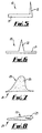
- Figure 5 shows a second example of an insert 10 that includes a base portion 11 with a fin 12 extending from one edge of the base portion 11. As with the insert 2, the fin 12 extends along the length of the insert 10.
- Figure 6 shows a third example of an insert 20 that includes a base portion 21 with a fin 22 extending centrally from the base portion 21. As with the inserts 2, 10 the fin 22 extends along the length of the insert 20.
- Figures 7 and 8 show a fourth example of an insert 24 that has a fin 23 formed from an elastically compressible foam material 25, such as a polyurethane foam.
- Figure 7 shows the insert 24 with the fin 23 in the extended position and
- Figure 8 shows the insert 24 with the foam material 25 compressed so that the fin 23 is collapsed.
- the inserts 10, 20, 24 may be used in the stent 1 in the same manner as the insert 2.
- the helical formations 2, 10, 20, 24 may each have a pitch, in relation to their length, such that one end is angularly displaced from the other by at least 50% of one revolution and preferably at least 70% of one revolution. This is found to impart favourable spiral flow to flow in a vein or artery, eliminating, or at least reducing, turbulence and dead spots with reduction of plaque formation.
- a biocompatible material will be selected, and a smooth structure with rounded ends will be preferred so as not to introduce any turbulence into the flow.
Landscapes
- Health & Medical Sciences (AREA)
- Engineering & Computer Science (AREA)
- Biomedical Technology (AREA)
- Veterinary Medicine (AREA)
- Public Health (AREA)
- Transplantation (AREA)
- Cardiology (AREA)
- Oral & Maxillofacial Surgery (AREA)
- Heart & Thoracic Surgery (AREA)
- Vascular Medicine (AREA)
- Life Sciences & Earth Sciences (AREA)
- Animal Behavior & Ethology (AREA)
- General Health & Medical Sciences (AREA)
- Fluid Mechanics (AREA)
- Gastroenterology & Hepatology (AREA)
- Physics & Mathematics (AREA)
- Pulmonology (AREA)
- Mechanical Engineering (AREA)
- General Engineering & Computer Science (AREA)
- Media Introduction/Drainage Providing Device (AREA)
- Prostheses (AREA)
- Lining Or Joining Of Plastics Or The Like (AREA)
- Extrusion Moulding Of Plastics Or The Like (AREA)
- Steering Control In Accordance With Driving Conditions (AREA)
- Containers And Plastic Fillers For Packaging (AREA)
- Endoscopes (AREA)
- Measuring Pulse, Heart Rate, Blood Pressure Or Blood Flow (AREA)
- Details Of Indoor Wiring (AREA)
- Materials For Medical Uses (AREA)
- Polymerisation Methods In General (AREA)
Applications Claiming Priority (2)
| Application Number | Priority Date | Filing Date | Title |
|---|---|---|---|
| GB0127888 | 2001-11-21 | ||
| GB0127888A GB2382776A (en) | 2001-11-21 | 2001-11-21 | Helix shaped insert for flow modification in a duct or stent |
Publications (3)
| Publication Number | Publication Date |
|---|---|
| EP1314406A2 true EP1314406A2 (de) | 2003-05-28 |
| EP1314406A3 EP1314406A3 (de) | 2004-04-21 |
| EP1314406B1 EP1314406B1 (de) | 2007-07-11 |
Family
ID=9926172
Family Applications (2)
| Application Number | Title | Priority Date | Filing Date |
|---|---|---|---|
| EP02258031A Expired - Lifetime EP1314406B1 (de) | 2001-11-21 | 2002-11-21 | Einsatz für einen Stent |
| EP02779716A Expired - Lifetime EP1446073B1 (de) | 2001-11-21 | 2002-11-21 | Spiralförmige vorrichtung für ein rohr |
Family Applications After (1)
| Application Number | Title | Priority Date | Filing Date |
|---|---|---|---|
| EP02779716A Expired - Lifetime EP1446073B1 (de) | 2001-11-21 | 2002-11-21 | Spiralförmige vorrichtung für ein rohr |
Country Status (9)
| Country | Link |
|---|---|
| US (3) | US7185677B2 (de) |
| EP (2) | EP1314406B1 (de) |
| AT (2) | ATE424158T1 (de) |
| AU (2) | AU2002343073A1 (de) |
| DE (2) | DE60231423D1 (de) |
| DK (1) | DK1446073T3 (de) |
| ES (2) | ES2321385T3 (de) |
| GB (2) | GB2382776A (de) |
| WO (2) | WO2003045279A1 (de) |
Cited By (6)
| Publication number | Priority date | Publication date | Assignee | Title |
|---|---|---|---|---|
| WO2004047908A3 (en) * | 2002-11-23 | 2004-12-23 | Tayside Flow Technologies Ltd | A helical formation for a conduit |
| WO2005004751A1 (en) * | 2003-07-04 | 2005-01-20 | Tayside Flow Technologies Limited | An internal formation for a conduit |
| WO2005077305A1 (en) | 2004-02-06 | 2005-08-25 | Tayside Flow Technologies Ltd | A drug delivery device |
| EP2264347A1 (de) * | 2009-06-12 | 2010-12-22 | Dietrich Wetzel KG | Selbstreinigungs- und/oder Fördervorrichtung und/oder druck- und/oder reibungsverlustbeeinflussende Struktur |
| US8133277B2 (en) | 2004-10-21 | 2012-03-13 | Bard Peripheral Vascular, Inc. | Medical device for fluid flow and method of forming such device |
| US20200339925A1 (en) * | 2019-04-26 | 2020-10-29 | Volumetric Biotechnologies, Inc. | Multivascular networks and functional intravascular topologies within biocompatible hydrogels |
Families Citing this family (30)
| Publication number | Priority date | Publication date | Assignee | Title |
|---|---|---|---|---|
| US20040267349A1 (en) | 2003-06-27 | 2004-12-30 | Kobi Richter | Amorphous metal alloy medical devices |
| US8382821B2 (en) | 1998-12-03 | 2013-02-26 | Medinol Ltd. | Helical hybrid stent |
| GB9828696D0 (en) * | 1998-12-29 | 1999-02-17 | Houston J G | Blood-flow tubing |
| CN1172299C (zh) | 1999-10-30 | 2004-10-20 | 三星电子株式会社 | 光学头 |
| US7390331B2 (en) | 2001-05-22 | 2008-06-24 | Sanostec Corp | Nasal inserts |
| US8403954B2 (en) | 2001-05-22 | 2013-03-26 | Sanostec Corp. | Nasal congestion, obstruction relief, and drug delivery |
| GB2369797B (en) | 2001-11-20 | 2002-11-06 | Tayside Flow Technologies Ltd | Helical formations in tubes |
| GB2382776A (en) | 2001-11-21 | 2003-06-11 | Tayside Flow Technologies Ltd | Helix shaped insert for flow modification in a duct or stent |
| US9155639B2 (en) * | 2009-04-22 | 2015-10-13 | Medinol Ltd. | Helical hybrid stent |
| US9039755B2 (en) * | 2003-06-27 | 2015-05-26 | Medinol Ltd. | Helical hybrid stent |
| GB2418362C (en) * | 2004-09-22 | 2010-05-05 | Veryan Medical Ltd | Stent |
| US8808354B2 (en) | 2004-09-22 | 2014-08-19 | Veryan Medical Limited | Helical stent |
| US20060085065A1 (en) * | 2004-10-15 | 2006-04-20 | Krause Arthur A | Stent with auxiliary treatment structure |
| US7988723B2 (en) | 2007-08-02 | 2011-08-02 | Flexible Stenting Solutions, Inc. | Flexible stent |
| US8376053B2 (en) * | 2007-10-01 | 2013-02-19 | Premium Artificial Lift Systems Ltd. | Fluid flow conduit, method and use |
| CN101854975A (zh) | 2007-10-03 | 2010-10-06 | 桑诺斯泰克公司 | 鼻腔插入物 |
| US8231686B2 (en) * | 2008-06-11 | 2012-07-31 | Eric Mangiardi | Stent |
| US9149376B2 (en) | 2008-10-06 | 2015-10-06 | Cordis Corporation | Reconstrainable stent delivery system |
| DE102008050618B3 (de) * | 2008-10-09 | 2010-04-01 | Roland Kuffer | Vorrichtung zum Absorbieren von elektromagnetischer Strahlung |
| US20100298924A1 (en) * | 2009-05-19 | 2010-11-25 | Tayside Flow Technologies Ltd. | Vascular Graft |
| US9095420B2 (en) * | 2011-01-24 | 2015-08-04 | Tufts Medical Center, Inc. | Endovascular stent |
| GB2498581A (en) * | 2012-01-23 | 2013-07-24 | Rolls Royce Plc | Pipe inspection probing cable having an external helical track |
| GB2514135B (en) * | 2013-05-14 | 2015-04-15 | Cook Medical Technologies Llc | Implantable flow diverter |
| GB2519932B (en) * | 2013-08-13 | 2015-10-21 | Cook Medical Technologies Llc | Implantable flow adjuster |
| US9561320B2 (en) | 2014-06-05 | 2017-02-07 | Cook Medical Technologies Llc | Device for promoting fistula patency and method |
| EP2952142B1 (de) | 2014-06-06 | 2017-09-06 | Cook Medical Technologies LLC | Vorrichtung zur ausbildung einer fistel zwischen blutgefässen |
| US10022252B2 (en) | 2015-06-10 | 2018-07-17 | Cook Medical Technologies Llc | Spiral blood flow device with diameter independent helix angle |
| US11491002B2 (en) * | 2015-08-14 | 2022-11-08 | Indian Institute Of Technology Bombay | Implantable cardio-vascular flow streamliner |
| CN110645237B (zh) * | 2019-09-02 | 2022-01-14 | 厦门理工学院 | 一种管道导流装置 |
| US12478488B2 (en) | 2020-02-19 | 2025-11-25 | Medinol Ltd. | Helical stent with enhanced crimping |
Citations (1)
| Publication number | Priority date | Publication date | Assignee | Title |
|---|---|---|---|---|
| WO2000038591A2 (en) | 1998-12-29 | 2000-07-06 | Tayside University Hospitals Nhs Trust | Blood-flow tubing |
Family Cites Families (50)
| Publication number | Priority date | Publication date | Assignee | Title |
|---|---|---|---|---|
| DE597472C (de) | 1936-01-18 | Arthur Kuhlmann | Als Leitflaeche in Rohre eingebaute Spirale | |
| US606311A (en) * | 1898-06-28 | sydenham | ||
| US2831662A (en) * | 1953-09-14 | 1958-04-22 | Century Electric Company | Fluid cooled dynamo electric machine |
| DE2510169A1 (de) | 1975-03-08 | 1976-09-16 | Albert Ziegler Kg | Fluessigkeitsleitung, z.b. schlauch |
| US4161966A (en) * | 1975-10-23 | 1979-07-24 | Kabel-Und Metallwerke Gutehoffnungshutte Aktiengesellschaft | Spacer for coaxial tube systems |
| CA1204643A (en) * | 1981-09-16 | 1986-05-20 | Hans I. Wallsten | Device for application in blood vessels or other difficulty accessible locations and its use |
| JPS5923985Y2 (ja) | 1981-10-13 | 1984-07-16 | 株式会社ミハマ製作所 | 合成樹脂製乱流子 |
| US4420019A (en) * | 1982-04-05 | 1983-12-13 | Dillon Joseph C | Flexible, non-kinkable hose and method for making the same |
| NL8403279A (nl) * | 1984-10-30 | 1986-05-16 | Philips Nv | Warmtewisselaar voor twee laminair stromende vloeistoffen. |
| US4629458A (en) * | 1985-02-26 | 1986-12-16 | Cordis Corporation | Reinforcing structure for cardiovascular graft |
| US4596548A (en) * | 1985-03-25 | 1986-06-24 | Dlp Inc. | Single stage venous catheter |
| SE450809B (sv) * | 1985-04-10 | 1987-08-03 | Medinvent Sa | Plant emne avsett for tillverkning av en spiralfjeder lemplig for transluminal implantation samt derav tillverkad spiralfjeder |
| JPS62144738A (ja) * | 1985-12-20 | 1987-06-27 | Hisao Kojima | 流体混合器 |
| SU1613835A2 (ru) * | 1987-11-02 | 1990-12-15 | Предприятие П/Я Г-4371 | Теплообменна труба |
| FI900794A7 (fi) * | 1988-07-05 | 1990-02-16 | Voith Gmbh J M | Laite paalin vannetuksen katkaistujen vanteiden poistamiseksi |
| FI85223C (fi) * | 1988-11-10 | 1992-03-25 | Biocon Oy | Biodegraderande kirurgiska implant och medel. |
| JPH062726Y2 (ja) * | 1989-06-23 | 1994-01-26 | 住友軽金属工業株式会社 | ねじり板挿入管を有するミスト回収装置 |
| FR2655548A1 (fr) | 1989-12-11 | 1991-06-14 | Cleef Jean Francois Van | Catheter a parois non lisses, catheter a parois moulurees. |
| FR2665237B1 (fr) * | 1990-07-27 | 1992-11-13 | Coflexip | Carcasse et conduite tubulaire flexible comportant une telle carcasse. |
| US5282847A (en) * | 1991-02-28 | 1994-02-01 | Medtronic, Inc. | Prosthetic vascular grafts with a pleated structure |
| US5129910A (en) * | 1991-07-26 | 1992-07-14 | The Regents Of The University Of California | Stone expulsion stent |
| US5500013A (en) * | 1991-10-04 | 1996-03-19 | Scimed Life Systems, Inc. | Biodegradable drug delivery vascular stent |
| JP3120163B2 (ja) * | 1992-07-22 | 2000-12-25 | 金尾 茂樹 | 導電線内装クリーナーホース |
| FR2708327B1 (fr) * | 1993-07-01 | 1995-10-13 | Hutchinson | Profilé tubulaire, à usage de joint d'étanchéité, de silencieux ou de conduit flexible pour véhicule automobile. |
| CA2169549C (en) * | 1993-08-18 | 2000-07-11 | James D. Lewis | A tubular intraluminal graft |
| US5486191A (en) * | 1994-02-02 | 1996-01-23 | John Hopkins University | Winged biliary stent |
| US6190402B1 (en) | 1996-06-21 | 2001-02-20 | Musc Foundation For Research Development | Insitu formable and self-forming intravascular flow modifier (IFM) and IFM assembly for deployment of same |
| US5992465A (en) * | 1996-08-02 | 1999-11-30 | Jansen; Robert C. | Flow system for pipes, pipe fittings, ducts and ducting elements |
| ZA9710342B (en) * | 1996-11-25 | 1998-06-10 | Alza Corp | Directional drug delivery stent and method of use. |
| US5954104A (en) | 1997-02-28 | 1999-09-21 | Abbott Laboratories | Container cap assembly having an enclosed penetrator |
| CH691846A5 (fr) * | 1997-06-20 | 2001-11-15 | Ecole Polytech | Implant de dilatation intravasculaire à déflecteur. |
| EP0891752B1 (de) * | 1997-07-17 | 2005-01-12 | Schneider (Europe) GmbH | Stent sowie Herstellungsverfahren dafür |
| US6161399A (en) * | 1997-10-24 | 2000-12-19 | Iowa-India Investments Company Limited | Process for manufacturing a wire reinforced monolayer fabric stent |
| US6156062A (en) * | 1997-12-03 | 2000-12-05 | Ave Connaught | Helically wrapped interlocking stent |
| US6063111A (en) * | 1998-03-31 | 2000-05-16 | Cordis Corporation | Stent aneurysm treatment system and method |
| US6019779A (en) * | 1998-10-09 | 2000-02-01 | Intratherapeutics Inc. | Multi-filar coil medical stent |
| US6248122B1 (en) * | 1999-02-26 | 2001-06-19 | Vascular Architects, Inc. | Catheter with controlled release endoluminal prosthesis |
| US20030225453A1 (en) * | 1999-03-03 | 2003-12-04 | Trivascular, Inc. | Inflatable intraluminal graft |
| US6364904B1 (en) * | 1999-07-02 | 2002-04-02 | Scimed Life Systems, Inc. | Helically formed stent/graft assembly |
| US6340364B2 (en) * | 1999-10-22 | 2002-01-22 | Nozomu Kanesaka | Vascular filtering device |
| US20010053931A1 (en) * | 1999-11-24 | 2001-12-20 | Salvatore J. Abbruzzese | Thin-layered, endovascular silk-covered stent device and method of manufacture thereof |
| DE10003619B4 (de) * | 2000-01-28 | 2005-09-08 | Rexroth Star Gmbh | Mutterneinheit |
| US20040249436A1 (en) | 2000-05-19 | 2004-12-09 | Aznoian Harold M. | Stents and stenting methods |
| US6645221B1 (en) * | 2000-05-30 | 2003-11-11 | Zuli, Holdings Ltd. | Active arterial embolization filter |
| US6675901B2 (en) * | 2000-06-01 | 2004-01-13 | Schlumberger Technology Corp. | Use of helically wound tubular structure in the downhole environment |
| US6572648B1 (en) * | 2000-06-30 | 2003-06-03 | Vascular Architects, Inc. | Endoluminal prosthesis and tissue separation condition treatment method |
| US6416540B1 (en) * | 2000-11-01 | 2002-07-09 | Sandip V. Mathur | Magnetically actuated cleanable stent and method |
| GB2379996B (en) * | 2001-06-05 | 2004-05-19 | Tayside Flow Technologies Ltd | Flow means |
| GB2382776A (en) | 2001-11-21 | 2003-06-11 | Tayside Flow Technologies Ltd | Helix shaped insert for flow modification in a duct or stent |
| GB0227369D0 (en) * | 2002-11-23 | 2002-12-31 | Tayside Flow Technologies Ltd | A helical formation for a conduit |
-
2001
- 2001-11-21 GB GB0127888A patent/GB2382776A/en not_active Withdrawn
- 2001-11-21 GB GB0305703A patent/GB2384189A/en not_active Withdrawn
-
2002
- 2002-11-21 AT AT02779716T patent/ATE424158T1/de active
- 2002-11-21 EP EP02258031A patent/EP1314406B1/de not_active Expired - Lifetime
- 2002-11-21 WO PCT/GB2002/005242 patent/WO2003045279A1/en not_active Ceased
- 2002-11-21 US US10/496,212 patent/US7185677B2/en not_active Expired - Lifetime
- 2002-11-21 AU AU2002343073A patent/AU2002343073A1/en not_active Abandoned
- 2002-11-21 DK DK02779716T patent/DK1446073T3/da active
- 2002-11-21 DE DE60231423T patent/DE60231423D1/de not_active Expired - Lifetime
- 2002-11-21 AT AT02258031T patent/ATE366560T1/de not_active IP Right Cessation
- 2002-11-21 AU AU2002343055A patent/AU2002343055A1/en not_active Abandoned
- 2002-11-21 ES ES02779716T patent/ES2321385T3/es not_active Expired - Lifetime
- 2002-11-21 EP EP02779716A patent/EP1446073B1/de not_active Expired - Lifetime
- 2002-11-21 ES ES02258031T patent/ES2288540T3/es not_active Expired - Lifetime
- 2002-11-21 US US10/301,257 patent/US7331989B2/en not_active Expired - Lifetime
- 2002-11-21 DE DE60221085T patent/DE60221085T2/de not_active Expired - Lifetime
- 2002-11-21 WO PCT/GB2002/005276 patent/WO2003045280A1/en not_active Ceased
-
2008
- 2008-01-17 US US12/009,269 patent/US8021415B2/en not_active Expired - Fee Related
Patent Citations (1)
| Publication number | Priority date | Publication date | Assignee | Title |
|---|---|---|---|---|
| WO2000038591A2 (en) | 1998-12-29 | 2000-07-06 | Tayside University Hospitals Nhs Trust | Blood-flow tubing |
Cited By (7)
| Publication number | Priority date | Publication date | Assignee | Title |
|---|---|---|---|---|
| WO2004047908A3 (en) * | 2002-11-23 | 2004-12-23 | Tayside Flow Technologies Ltd | A helical formation for a conduit |
| WO2005004751A1 (en) * | 2003-07-04 | 2005-01-20 | Tayside Flow Technologies Limited | An internal formation for a conduit |
| US8454675B2 (en) | 2003-07-04 | 2013-06-04 | Tayside Flow Technologies Ltd. | Internal formation for a conduit |
| WO2005077305A1 (en) | 2004-02-06 | 2005-08-25 | Tayside Flow Technologies Ltd | A drug delivery device |
| US8133277B2 (en) | 2004-10-21 | 2012-03-13 | Bard Peripheral Vascular, Inc. | Medical device for fluid flow and method of forming such device |
| EP2264347A1 (de) * | 2009-06-12 | 2010-12-22 | Dietrich Wetzel KG | Selbstreinigungs- und/oder Fördervorrichtung und/oder druck- und/oder reibungsverlustbeeinflussende Struktur |
| US20200339925A1 (en) * | 2019-04-26 | 2020-10-29 | Volumetric Biotechnologies, Inc. | Multivascular networks and functional intravascular topologies within biocompatible hydrogels |
Also Published As
| Publication number | Publication date |
|---|---|
| GB0127888D0 (en) | 2002-01-16 |
| GB2384189A (en) | 2003-07-23 |
| WO2003045279A1 (en) | 2003-06-05 |
| GB2382776A (en) | 2003-06-11 |
| US20080114448A1 (en) | 2008-05-15 |
| ES2288540T3 (es) | 2008-01-16 |
| EP1446073A1 (de) | 2004-08-18 |
| US20050061380A1 (en) | 2005-03-24 |
| US20030139807A1 (en) | 2003-07-24 |
| DE60221085D1 (de) | 2007-08-23 |
| ES2321385T3 (es) | 2009-06-05 |
| DE60221085T2 (de) | 2008-03-20 |
| DE60231423D1 (de) | 2009-04-16 |
| AU2002343055A1 (en) | 2003-06-10 |
| DK1446073T3 (da) | 2009-06-22 |
| EP1314406A3 (de) | 2004-04-21 |
| WO2003045280A1 (en) | 2003-06-05 |
| AU2002343073A1 (en) | 2003-06-10 |
| US7185677B2 (en) | 2007-03-06 |
| GB0305703D0 (en) | 2003-04-16 |
| ATE366560T1 (de) | 2007-08-15 |
| EP1314406B1 (de) | 2007-07-11 |
| US7331989B2 (en) | 2008-02-19 |
| US8021415B2 (en) | 2011-09-20 |
| ATE424158T1 (de) | 2009-03-15 |
| EP1446073B1 (de) | 2009-03-04 |
Similar Documents
| Publication | Publication Date | Title |
|---|---|---|
| US8021415B2 (en) | Insert for a conduit | |
| US6860900B2 (en) | Stent and stent-graft for treating branched vessels | |
| US9949852B2 (en) | Implant for supporting bodily conduits such as blood vessels or/and grafted vessels | |
| US6083258A (en) | Locking stent | |
| JP6310115B2 (ja) | 吻合装置及び方法 | |
| US6149682A (en) | Luminal endoprosthesis for ramification | |
| KR102471626B1 (ko) | 스텐트 보철 | |
| US20030083734A1 (en) | Stent | |
| JP2011511701A (ja) | 軸方向に変化可能な特性を有するグラフト内部フレーム | |
| KR20020012574A (ko) | 증가된 유연성을 갖는 스텐트-이식편 | |
| CN111329634B (zh) | 植入物 | |
| US20060155355A1 (en) | Stent to be implanted within or around a hollow organ | |
| EP4054490B1 (de) | Stents, die vorstehende merkmale zum verankern aufweisen | |
| US8551153B2 (en) | Prosthesis comprising a coiled stent and method of use thereof | |
| EP1477134A2 (de) | Stent und Stent-Transplantat zur Behandlung von verzweigten Blutgefässen | |
| US20240366363A1 (en) | Venous stent | |
| JP2004305450A (ja) | 血管追従性の優れた均一に拡張する柔軟なステント | |
| CA3091391A1 (en) | Methods and apparatus for enhanced flow stent device | |
| US20140277368A1 (en) | Prosthesis comprising a coiled stent and method of use thereof |
Legal Events
| Date | Code | Title | Description |
|---|---|---|---|
| PUAI | Public reference made under article 153(3) epc to a published international application that has entered the european phase |
Free format text: ORIGINAL CODE: 0009012 |
|
| AK | Designated contracting states |
Designated state(s): AT BE BG CH CY CZ DE DK EE ES FI FR GB GR IE IT LI LU MC NL PT SE SK TR |
|
| AX | Request for extension of the european patent |
Extension state: AL LT LV MK RO SI |
|
| PUAL | Search report despatched |
Free format text: ORIGINAL CODE: 0009013 |
|
| AK | Designated contracting states |
Kind code of ref document: A3 Designated state(s): AT BE BG CH CY CZ DE DK EE ES FI FR GB GR IE IT LI LU MC NL PT SE SK TR |
|
| AX | Request for extension of the european patent |
Extension state: AL LT LV MK RO SI |
|
| 17P | Request for examination filed |
Effective date: 20041019 |
|
| AKX | Designation fees paid |
Designated state(s): AT BE BG CH CY CZ DE DK EE ES FI FR GB GR IE IT LI LU MC NL PT SE SK TR |
|
| RIC1 | Information provided on ipc code assigned before grant |
Ipc: A61F 2/82 20060101AFI20060710BHEP Ipc: F16L 55/027 20060101ALI20060710BHEP Ipc: F15D 1/02 20060101ALI20060710BHEP |
|
| RTI1 | Title (correction) |
Free format text: AN INSERT FOR A STENT |
|
| RAP1 | Party data changed (applicant data changed or rights of an application transferred) |
Owner name: TAYSIDE FLOW TECHNOLOGIES LIMITED |
|
| RIN1 | Information on inventor provided before grant (corrected) |
Inventor name: DICK, JOHN BRICE CAMERON Inventor name: HOOD, ROBERT GORDON Inventor name: HOUSTON, JOHN GRAEME Inventor name: JOHNSTONE, ALLANA Inventor name: SARRAN, CHRISTOPHE EMMANUEL Inventor name: DUFF, CRAIG MCLEOD Inventor name: STONEBRIDGE, PETER ARNO |
|
| GRAP | Despatch of communication of intention to grant a patent |
Free format text: ORIGINAL CODE: EPIDOSNIGR1 |
|
| RAP1 | Party data changed (applicant data changed or rights of an application transferred) |
Owner name: TAYSIDE FLOW TECHNOLOGIES LIMITED |
|
| GRAS | Grant fee paid |
Free format text: ORIGINAL CODE: EPIDOSNIGR3 |
|
| GRAA | (expected) grant |
Free format text: ORIGINAL CODE: 0009210 |
|
| AK | Designated contracting states |
Kind code of ref document: B1 Designated state(s): AT BE BG CH CY CZ DE DK EE ES FI FR GB GR IE IT LI LU MC NL PT SE SK TR |
|
| REG | Reference to a national code |
Ref country code: GB Ref legal event code: FG4D |
|
| REG | Reference to a national code |
Ref country code: CH Ref legal event code: EP |
|
| REF | Corresponds to: |
Ref document number: 60221085 Country of ref document: DE Date of ref document: 20070823 Kind code of ref document: P |
|
| REG | Reference to a national code |
Ref country code: IE Ref legal event code: FG4D |
|
| ET | Fr: translation filed | ||
| REG | Reference to a national code |
Ref country code: ES Ref legal event code: FG2A Ref document number: 2288540 Country of ref document: ES Kind code of ref document: T3 |
|
| PG25 | Lapsed in a contracting state [announced via postgrant information from national office to epo] |
Ref country code: PT Free format text: LAPSE BECAUSE OF FAILURE TO SUBMIT A TRANSLATION OF THE DESCRIPTION OR TO PAY THE FEE WITHIN THE PRESCRIBED TIME-LIMIT Effective date: 20071211 Ref country code: BG Free format text: LAPSE BECAUSE OF FAILURE TO SUBMIT A TRANSLATION OF THE DESCRIPTION OR TO PAY THE FEE WITHIN THE PRESCRIBED TIME-LIMIT Effective date: 20071011 Ref country code: FI Free format text: LAPSE BECAUSE OF FAILURE TO SUBMIT A TRANSLATION OF THE DESCRIPTION OR TO PAY THE FEE WITHIN THE PRESCRIBED TIME-LIMIT Effective date: 20070711 |
|
| REG | Reference to a national code |
Ref country code: CH Ref legal event code: PL |
|
| PG25 | Lapsed in a contracting state [announced via postgrant information from national office to epo] |
Ref country code: LI Free format text: LAPSE BECAUSE OF FAILURE TO SUBMIT A TRANSLATION OF THE DESCRIPTION OR TO PAY THE FEE WITHIN THE PRESCRIBED TIME-LIMIT Effective date: 20070711 Ref country code: CH Free format text: LAPSE BECAUSE OF FAILURE TO SUBMIT A TRANSLATION OF THE DESCRIPTION OR TO PAY THE FEE WITHIN THE PRESCRIBED TIME-LIMIT Effective date: 20070711 Ref country code: AT Free format text: LAPSE BECAUSE OF FAILURE TO SUBMIT A TRANSLATION OF THE DESCRIPTION OR TO PAY THE FEE WITHIN THE PRESCRIBED TIME-LIMIT Effective date: 20070711 |
|
| PG25 | Lapsed in a contracting state [announced via postgrant information from national office to epo] |
Ref country code: BE Free format text: LAPSE BECAUSE OF FAILURE TO SUBMIT A TRANSLATION OF THE DESCRIPTION OR TO PAY THE FEE WITHIN THE PRESCRIBED TIME-LIMIT Effective date: 20070711 |
|
| PG25 | Lapsed in a contracting state [announced via postgrant information from national office to epo] |
Ref country code: DK Free format text: LAPSE BECAUSE OF FAILURE TO SUBMIT A TRANSLATION OF THE DESCRIPTION OR TO PAY THE FEE WITHIN THE PRESCRIBED TIME-LIMIT Effective date: 20070711 Ref country code: GR Free format text: LAPSE BECAUSE OF FAILURE TO SUBMIT A TRANSLATION OF THE DESCRIPTION OR TO PAY THE FEE WITHIN THE PRESCRIBED TIME-LIMIT Effective date: 20071012 |
|
| PLBE | No opposition filed within time limit |
Free format text: ORIGINAL CODE: 0009261 |
|
| STAA | Information on the status of an ep patent application or granted ep patent |
Free format text: STATUS: NO OPPOSITION FILED WITHIN TIME LIMIT |
|
| PG25 | Lapsed in a contracting state [announced via postgrant information from national office to epo] |
Ref country code: CZ Free format text: LAPSE BECAUSE OF FAILURE TO SUBMIT A TRANSLATION OF THE DESCRIPTION OR TO PAY THE FEE WITHIN THE PRESCRIBED TIME-LIMIT Effective date: 20070711 Ref country code: SK Free format text: LAPSE BECAUSE OF FAILURE TO SUBMIT A TRANSLATION OF THE DESCRIPTION OR TO PAY THE FEE WITHIN THE PRESCRIBED TIME-LIMIT Effective date: 20070711 |
|
| 26N | No opposition filed |
Effective date: 20080414 |
|
| PG25 | Lapsed in a contracting state [announced via postgrant information from national office to epo] |
Ref country code: SE Free format text: LAPSE BECAUSE OF FAILURE TO SUBMIT A TRANSLATION OF THE DESCRIPTION OR TO PAY THE FEE WITHIN THE PRESCRIBED TIME-LIMIT Effective date: 20071011 Ref country code: MC Free format text: LAPSE BECAUSE OF NON-PAYMENT OF DUE FEES Effective date: 20071130 |
|
| PG25 | Lapsed in a contracting state [announced via postgrant information from national office to epo] |
Ref country code: IE Free format text: LAPSE BECAUSE OF NON-PAYMENT OF DUE FEES Effective date: 20071121 |
|
| PG25 | Lapsed in a contracting state [announced via postgrant information from national office to epo] |
Ref country code: EE Free format text: LAPSE BECAUSE OF FAILURE TO SUBMIT A TRANSLATION OF THE DESCRIPTION OR TO PAY THE FEE WITHIN THE PRESCRIBED TIME-LIMIT Effective date: 20070711 |
|
| PG25 | Lapsed in a contracting state [announced via postgrant information from national office to epo] |
Ref country code: CY Free format text: LAPSE BECAUSE OF FAILURE TO SUBMIT A TRANSLATION OF THE DESCRIPTION OR TO PAY THE FEE WITHIN THE PRESCRIBED TIME-LIMIT Effective date: 20070711 |
|
| PG25 | Lapsed in a contracting state [announced via postgrant information from national office to epo] |
Ref country code: LU Free format text: LAPSE BECAUSE OF NON-PAYMENT OF DUE FEES Effective date: 20071121 |
|
| PG25 | Lapsed in a contracting state [announced via postgrant information from national office to epo] |
Ref country code: TR Free format text: LAPSE BECAUSE OF FAILURE TO SUBMIT A TRANSLATION OF THE DESCRIPTION OR TO PAY THE FEE WITHIN THE PRESCRIBED TIME-LIMIT Effective date: 20070711 |
|
| REG | Reference to a national code |
Ref country code: FR Ref legal event code: PLFP Year of fee payment: 14 |
|
| REG | Reference to a national code |
Ref country code: FR Ref legal event code: PLFP Year of fee payment: 15 |
|
| REG | Reference to a national code |
Ref country code: FR Ref legal event code: PLFP Year of fee payment: 16 |
|
| PGFP | Annual fee paid to national office [announced via postgrant information from national office to epo] |
Ref country code: IT Payment date: 20181107 Year of fee payment: 17 |
|
| PG25 | Lapsed in a contracting state [announced via postgrant information from national office to epo] |
Ref country code: IT Free format text: LAPSE BECAUSE OF NON-PAYMENT OF DUE FEES Effective date: 20191121 |
|
| REG | Reference to a national code |
Ref country code: ES Ref legal event code: FD2A Effective date: 20210528 |
|
| PG25 | Lapsed in a contracting state [announced via postgrant information from national office to epo] |
Ref country code: ES Free format text: LAPSE BECAUSE OF NON-PAYMENT OF DUE FEES Effective date: 20191122 |
|
| PGFP | Annual fee paid to national office [announced via postgrant information from national office to epo] |
Ref country code: DE Payment date: 20211103 Year of fee payment: 20 Ref country code: NL Payment date: 20211103 Year of fee payment: 20 Ref country code: GB Payment date: 20211103 Year of fee payment: 20 Ref country code: FR Payment date: 20211103 Year of fee payment: 20 |
|
| REG | Reference to a national code |
Ref country code: DE Ref legal event code: R071 Ref document number: 60221085 Country of ref document: DE |
|
| REG | Reference to a national code |
Ref country code: NL Ref legal event code: MK Effective date: 20221120 |
|
| REG | Reference to a national code |
Ref country code: GB Ref legal event code: PE20 Expiry date: 20221120 |
|
| PG25 | Lapsed in a contracting state [announced via postgrant information from national office to epo] |
Ref country code: GB Free format text: LAPSE BECAUSE OF EXPIRATION OF PROTECTION Effective date: 20221120 |