EP1314509A2 - Drehendes Reibungsschweissen - Google Patents
Drehendes Reibungsschweissen Download PDFInfo
- Publication number
- EP1314509A2 EP1314509A2 EP02258015A EP02258015A EP1314509A2 EP 1314509 A2 EP1314509 A2 EP 1314509A2 EP 02258015 A EP02258015 A EP 02258015A EP 02258015 A EP02258015 A EP 02258015A EP 1314509 A2 EP1314509 A2 EP 1314509A2
- Authority
- EP
- European Patent Office
- Prior art keywords
- friction stir
- stir welding
- rotating tool
- rotating
- tool
- Prior art date
- Legal status (The legal status is an assumption and is not a legal conclusion. Google has not performed a legal analysis and makes no representation as to the accuracy of the status listed.)
- Withdrawn
Links
Images


Classifications
-
- B—PERFORMING OPERATIONS; TRANSPORTING
- B23—MACHINE TOOLS; METAL-WORKING NOT OTHERWISE PROVIDED FOR
- B23K—SOLDERING OR UNSOLDERING; WELDING; CLADDING OR PLATING BY SOLDERING OR WELDING; CUTTING BY APPLYING HEAT LOCALLY, e.g. FLAME CUTTING; WORKING BY LASER BEAM
- B23K20/00—Non-electric welding by applying impact or other pressure, with or without the application of heat, e.g. cladding or plating
- B23K20/12—Non-electric welding by applying impact or other pressure, with or without the application of heat, e.g. cladding or plating the heat being generated by friction; Friction welding
- B23K20/122—Non-electric welding by applying impact or other pressure, with or without the application of heat, e.g. cladding or plating the heat being generated by friction; Friction welding using a non-consumable tool, e.g. friction stir welding
- B23K20/1245—Non-electric welding by applying impact or other pressure, with or without the application of heat, e.g. cladding or plating the heat being generated by friction; Friction welding using a non-consumable tool, e.g. friction stir welding characterised by the apparatus
- B23K20/1255—Tools therefor, e.g. characterised by the shape of the probe
-
- B—PERFORMING OPERATIONS; TRANSPORTING
- B23—MACHINE TOOLS; METAL-WORKING NOT OTHERWISE PROVIDED FOR
- B23K—SOLDERING OR UNSOLDERING; WELDING; CLADDING OR PLATING BY SOLDERING OR WELDING; CUTTING BY APPLYING HEAT LOCALLY, e.g. FLAME CUTTING; WORKING BY LASER BEAM
- B23K20/00—Non-electric welding by applying impact or other pressure, with or without the application of heat, e.g. cladding or plating
- B23K20/24—Preliminary treatment
Definitions
- the present invention relates to a rotating tool for friction stir welding which is adapted to perform friction stir welding of two works placed to be butted with each other while rotating and moving along the butted portion of the two works.
- a rotating tool used in this friction stir welding method is configured such that a shoulder portion having a pin for friction stir welding at a tip end is connected to a tip end side of a substantially cylindrical tool body.
- the pin at the tip end of the rotating tool is directed downward and inserted into the butted portion of the two works to a predetermined depth, in which state, the rotating tool moves along the butted portion while rotating at a high speed.
- This causes the temperature of the butted portion to be increased by friction heat due to sliding contact with the pin and the shoulder portion, and metal friction-stirred by the high-speed rotation of the rotating tool to plastic flow between the works, i.e., at the butted portion.
- the butted portion loses heat source and is thereby rapidly cooled.
- the two works are joined.
- the metal in a plastic flow state flows toward the opposite direction to the movement of the rotating tool while its upward flow above the works is restricted by the shoulder portion of the rotating tool, and after the pin has passed through, the corresponding portion is filled with the metal.
- the butted portion of the works is tack-welded by excess metals at even intervals prior to the friction stir welding, and in this state, the friction stir welding is carried out.
- the friction stir welding is not performed in the tack-welded sections, and therefore, the resulting weld strength is weaker than the weld strength obtained by the friction stir welding using the excess metals. Besides, since it is necessary to move the rotating tool upwardly before each of the tack-welded sections and then move the rotating tool downwardly after passing through the tack-welded sections, the operation of the rotating tool becomes complex, which leads to increased work time and reduced work efficiency.
- the rotating tool disclosed in Japanese Laid-Open Patent Application Publication No. 2001- 47258 is adapted to carry out friction stir welding of the works while exerting a downward force on burr occurred during the friction stir welding, and is incapable of removing the excess metals while the rotating tool is moving.
- the invention provides a rotatable tool for friction stir welding of two works, placed to be butted with each other by rotating and moving along a butted portion of the two works, the butted portion being tack-welded by excess metals before the friction stir welding, the rotating tool is characterized in that comprising:
- the invention also includes a method for performing friction stir welding of two works placed to be butted with each other by rotating and moving a rotating tool along a butted portion of the two works, the butted portion being tack-welded by excess metals before the friction stir welding; the method is characterized in that comprising the step of:
- the invention also includes an apparatus of friction stir welding of two works placed to be butted with each other by rotating and moving a rotating tool along a butted portion of the two works, the butted portion being tack-welded by excess metals before the friction stir welding, the apparatus is characterized in that comprising:
- the friction stir welding of the two works can be carried out while removing the excess metals by rotating and moving the rotating tool for friction stir welding along the butted portion of the two works placed to be butted with each other after the butted portion is tack-welded by the excess metals.
- the tack welding by the excess metals includes melting welding such as TIG welding and MIG welding.
- a cutting blade adapted to rotate and move along with the rotating tool is used.
- a pin of the rotating tool is inserted into the butted portion of the works to a predetermined depth and the rotating tool is rotated and moved along the butted portion of the works, which are friction-stir-welded while the excess metals of the tack-welded sections are removed by, for example, the cutting blade. Therefore, uniform plastic flow is caused to occur and uniform welding strength of the stir friction welding can be obtained over the entire length of the works (butted portion) including the tack-welded sections. Besides, since the tack-welding strength can be maintained by the excess metals during the friction stir welding, the butted portion can be welded without relative displacement between the two works. Further, since the excess metals are removed while the welding is performed, the excess metals do not obstruct friction stir welding.
- the rotating tool itself may have the cutting blade.
- the removal of the excess metals by the cutting blade and the friction stir welding of the works by the rotating tool can be accomplished at the same time merely by rotating and moving the rotating tool along the butted portion of the two works, similarly to the conventional friction stir welding.
- the rotating tool comprises a cylindrical tool body, a shoulder portion provided at a tip end side of the tool body, and a pin provided at a tip end of the shoulder portion, and the cutting blade is provided from the shoulder portion to a tip end portion of the tool body.
- the excess metals removed by the cutting blade are carried away along a cutting face of the cutting blade, from the position where the friction stir welding is being performed. Because the removed excess metals do not fall onto the position where the friction stir welding is being performed, they do not affect the welding.
- a plurality of cutting blades are symmetrically provided in the rotating tool.
- the plurality of cutting blades symmetrically provided can smoothly remove the excess metals properly in balance. This reduces the load on the rotating tools in contrast with the case where the excess metals are removed by using a single cutting blade.
- the inert gas includes a nitrogen gas, an argon gas, etc.
- an opening through which the inert gas is blown out to the cutting blade and its vicinity is formed in the cutting blade or its vicinity so as to communicate with an inert gas source.
- the rotating tool is installed in such a manner that, with the pin of the rotating tool directed downward, an upper portion of the rotating tool is clamped to a chuck of the friction stir welding apparatus.
- the opening is connected to the inert gas source.
- the penetrating hole of the rotating tool is connected to the gas source through a gas passage only by clamping the rotating tool to the chunk.
- a gas reservoir may be formed at an upper stream end of the penetrating hole of the rotating tool.
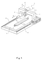
- a friction stir welding apparatus 1 comprises a flat bed 2 of a rectangular shape that is long in longitudinal or front and rear direction (X-direction).
- X-direction On the bed 2, long-plate-shaped works W1, W2 to be joined are placed along the X-direction.
- Y-direction On both sides of the bed 2 in lateral direction (Y-direction), a pair of rails 6 are provided to extend in parallel with each other along the X-direction.
- a gate-shaped frame 3 spanning over the bed 2 in the Y-direction is provided to be movable along the rails 6.
- the gate-shaped frame 3 is provided with a movable member 4 at a horizontal frame portion 3a constituting an upper portion thereof.
- the movable member 4 is movable along the Y-direction on the horizontal frame portion 3a by a slider 4a provided in the movable member 4.
- the movable member 4 is provided with a joint head 5 that is movable in the vertical direction (Z-direction).
- the joint head 5 contains a motor (not shown) in an upper portion thereof, and is provided with a rotating tool 11 for friction stir welding rotatably driven by the motor, at a lower end portion of the head 5.
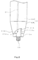
- the rotating tool 11 is configured such that a taper portion 12B is connected to a cylindrical portion 12A so as to extend from a tip end (lower end) of the cylindrical portion 12A.
- the cylindrical portion 12A and the taper portion 12B constitute a tool body 12.
- a cylindrical shoulder portion 14 is connected to a lower end portion of the taper portion 12B.
- a pin 15 for friction stir welding is protruded from a center portion of a tip end face of the shoulder portion 14.
- the shoulder portion 14 and the pin 15 are connected coaxially with the tool body 12.
- one or a plurality of (for example, two) cutting blades 11A are symmetrically provided for removing excess metals S (see Fig. 4).
- the cutting blades 11A of the rotating tool 11 are capable of removing the excess metals S during the friction stir welding.
- the cutting blades 11A are each constituted by a combination of two cutting faces 11Aa, 11Ab that form substantially 90 degrees at their tip end sides, and the cutting face 11Ab is curved such that depth of cut becomes smaller as it is away from the tip end.
- the cutting blades 11A can be formed from the shoulder portion 14 to the taper portion 12B in a simple manner without changing a basic shape of the conventional rotating tool.
- the removal of the excess metals S can be well-balanced.
- the cutting blades 11A Since the tip ends of the cutting blades 11A conform to the tip end face (lower end face) of the shoulder portion 14, the cutting blades 11A do not damage the surfaces of the works W1, W2 while the pin 15 is inserted into the butted portion of the works W1, W2 to a predetermined depth, and rotating and moving.
- the rotating tool 11 is made of a material harder and more rigid than a material of the works W1, W2.
- the works W1, W2 may, for example, be aluminum alloy parts.
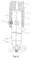
- the rotating tool 11 is configured such that the cylindrical portion 12A of the tool body 12 is provided with a concave portion 12a to which a tip end of a bolt 24 is applied, and a base end portion (upper end portion) of the cylindrical portion 12A is removably clamped to a chuck 22 provided in the joint head 5 by means of a plurality of bolts 24, although only one is illustrated in Fig. 4.
- the rotating tool 11 is provided with an atmosphere generating means for generating inert gas atmosphere over the cutting blades 11A and their vicinity during the friction stir welding.
- the atmosphere generating means has openings 21a provided in the cutting blades 11A or their vicinity, for example, in the vicinity of base portions of the cutting blades 11A. Through the openings 21a, the inert gas is blown out to the cutting blades 11A and their vicinity.
- the openings 21a are downstream end openings of penetrating hole(s) 21 penetrating the rotating tool 11 along its rotational axis.
- the chuck 22 is provided with a gas passage 23 connected to a gas source (not shown) of the inert gas, and the gas passage 23 communicates with a gas reservoir 21b located at an upper stream end of the penetrating holes 21.
- the mere clamping of the base end portion of the rotating tool 11 to the chuck 22 enables the rotating tool 11 to be connected to the gas source of the inert gas through the gas passage 23, so that the inert gas can be supplied to the cutting blades 11A and their vicinity.
- the gas passage 23 permits flow of the inert gas and is controlled to flow the inert gas at a predetermined amount when the rotating tool 11 is clamped to the chuck 22. On the other hand, when the rotating tool 11 is removed from the chuck 22, the gas passage 23 is controlled to block the flow of the inert gas.
- the friction stir welding apparatus of this embodiment is constituted as described above, and is adapted to carry out the friction stir welding as described below.
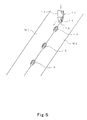
- the works W1, W2 are fixed by means of a jig (not shown) such that their longitudinal sections are butted with each other.
- the butted portion is tack-welded by the excess metals S (see Fig. 5) at even intervals.
- This tack-welding is performed by using a material similar to that of the works W1, W2.
- two tab plates j are welded to both ends of the works W1, W2, and the butted portion of the tab plates j is also welded.
- the gate-shaped frame 3 is moved along the X-direction, thereby moving the joint head 5 above and along the butted portion of the works W1, W2. While the joint head 5 is moved, the rotating tool 11 is rotated and moved along the butted portion under the condition in which its pressuring force is controlled.
- the pin 15 of the rotating tool 11 rotates at a high speed in the state in which the pin 15 is inserted into the butted portion of the works W1, W2, while the two cutting blades 11A are removing the excess metals S. Simultaneously, the temperature of the butted portion is increased by friction heat generated by sliding contact with the pin 15 and the shoulder portion 14, thereby causing metal friction-stirred by the rotation of the pin 15 to plastic flow between the works W1, W2. After the pin 15 has passed through, the works W1, W2 are rapidly cooled because of the losses of heat source, and are thereby joined.
- an inert gas is blown out through the openings 21a in the vicinity of the base portions of the cutting blades 11A and evenly supplied over from the base portions to the tip end portions of the cutting blades 11A and the area around them.
- the rotating tool 11 rotates to cause the cutting blades 11A to rotate to thereby remove the excess metals S, while ensuring tack-welding strength so as not to affect the friction stir welding. Since the cutting blades 11A are provided from the shoulder portion 14 to the taper portion 12B, the excess metals S removed by the cutting blades 11A are carried away from the joint portion along the cutting faces 11Aa, 11Ab of the cutting blades 11A. This follows that the excess metals S removed by the cutting blades 11A does not interfere with the friction stir welding of the butted portion of the works W1, W2.
- the rotating tool 11 since the rotating tool 11 operates such that friction stir welding is performed by using the pin 15 while the excess metal S is removed by the cutting blades 11A, it can be moved with the pin 15 inserted to the predetermined depth over the entire length of the butted portion of the works W1, W2 without additional processing of the excess metal S. This reduces time required for friction stir welding and significantly improves work efficiency.
- the number of the cutting blades 11A may be three or more, or may be one, instead of two as indicated.
- the two cutting blades 11A may be provided only at the shoulder portion 14 of the rotating tool 11, rather than from the shoulder portion 14 to the taper portion 12B.
- a cutting blade may be provided independently of the shoulder portion 14, or may be provided independently of the rotating tool 11 and adapted to move together with the rotating tool 11.
- a nozzle for blowing out the inert gas to the cutting blades 11A and their vicinity may be provided independently of the rotating tool 11. In that case, the nozzle moves along the butted portion of the works W1, W2 together with the rotating tool 11.
- the gas passage 23 is released when the rotating tool 11 is clamped to the chuck 22, in which released state, the rotating tool 11 is connected to the gas source.
- a valve may be provided in the gas passage 23 and opened after clamping to allow the rotating tool 11 to be connected to the gas source.
- the embodiments provide a rotating tool for friction stir welding with which uniform welding strength by the friction stir welding can be obtained over the entire length of works (butted portion) including tack-welded sections, and a method and apparatus of friction stir welding using the rotating tool.
- a pin of the rotating tool can be inserted to a predetermined depth over the entire length of the butted portion and uniform welding strength can be obtained there, by moving the rotating tool while removing excess metals of the tack-welded sections.
Landscapes
- Engineering & Computer Science (AREA)
- Mechanical Engineering (AREA)
- Pressure Welding/Diffusion-Bonding (AREA)
Applications Claiming Priority (4)
| Application Number | Priority Date | Filing Date | Title |
|---|---|---|---|
| JP2001360681 | 2001-11-27 | ||
| JP2001360680 | 2001-11-27 | ||
| JP2001360681A JP2003164977A (ja) | 2001-11-27 | 2001-11-27 | 摩擦攪拌接合用回転ツールおよびそれを用いた摩擦攪拌接合方法並びに摩擦攪拌接合装置 |
| JP2001360680A JP2003164976A (ja) | 2001-11-27 | 2001-11-27 | 摩擦攪拌接合用回転ツールおよびそれを用いた摩擦攪拌接合方法並びに摩擦攪拌接合装置 |
Publications (2)
| Publication Number | Publication Date |
|---|---|
| EP1314509A2 true EP1314509A2 (de) | 2003-05-28 |
| EP1314509A3 EP1314509A3 (de) | 2004-01-07 |
Family
ID=26624705
Family Applications (1)
| Application Number | Title | Priority Date | Filing Date |
|---|---|---|---|
| EP02258015A Withdrawn EP1314509A3 (de) | 2001-11-27 | 2002-11-21 | Drehendes Reibungsschweissen |
Country Status (3)
| Country | Link |
|---|---|
| US (1) | US20030098335A1 (de) |
| EP (1) | EP1314509A3 (de) |
| CN (1) | CN1421295A (de) |
Cited By (5)
| Publication number | Priority date | Publication date | Assignee | Title |
|---|---|---|---|---|
| RU2396155C1 (ru) * | 2009-03-17 | 2010-08-10 | Федеральное государственное унитарное предприятие "Государственный космический научно-производственный центр им. М.В. Хруничева" | Сварочная головка для фрикционной сварки |
| CN109570743A (zh) * | 2019-02-12 | 2019-04-05 | 黄山学院 | 一种带电阻丝加热装置的搅拌头 |
| US11065714B2 (en) | 2016-03-23 | 2021-07-20 | Grenzebach Maschinenbau Gmbh | Device and method for the residue-free friction stir welding of workpieces with height differences between the joint partners |
| WO2022137151A1 (en) * | 2020-12-22 | 2022-06-30 | Miwenti S.R.L. | Friction stir welding tool, welding method and sheet welding machine |
| RU2844519C2 (ru) * | 2020-12-22 | 2025-08-01 | Мивенти С.Р.Л. | Инструмент для сварки трением, способ сварки и аппарат для сварки листов |
Families Citing this family (28)
| Publication number | Priority date | Publication date | Assignee | Title |
|---|---|---|---|---|
| EP0928659B1 (de) * | 1997-12-19 | 2002-04-17 | Esab AB | Schweissvorrichtung |
| JP3510612B2 (ja) * | 2001-11-27 | 2004-03-29 | 川崎重工業株式会社 | 摩擦撹拌接合方法 |
| US6776328B2 (en) * | 2002-09-17 | 2004-08-17 | The Boeing Company | Radiation assisted friction welding |
| JP3498086B1 (ja) * | 2003-05-14 | 2004-02-16 | 川崎重工業株式会社 | 摩擦撹拌接合方法および摩擦撹拌接合装置 |
| US7036708B2 (en) * | 2003-09-09 | 2006-05-02 | Halla Climate Control Corporation | Manufacturing method of piston for swash plate type compressor with variable capacity |
| DE102005029882A1 (de) * | 2005-06-27 | 2006-12-28 | Gkss-Forschungszentrum Geesthacht Gmbh | Vorrichtung zum Reibrührschweißen |
| US20080202672A1 (en) * | 2007-02-23 | 2008-08-28 | Bradford Company | Method of Making Product From Fusible Sheets and/or Elements |
| US8066174B2 (en) * | 2010-04-30 | 2011-11-29 | Siemens Energy, Inc. | Filler rotated friction stir welding |
| CA2818740C (en) | 2010-11-23 | 2015-12-29 | Centre De Recherche Industrielle Du Quebec | Apparatus and method for inserting a component through the surface of a workpiece |
| US8708628B2 (en) | 2010-11-23 | 2014-04-29 | Centre De Recherche Industrielle Du Quebec | Insertion component and method for inserting thereof through the surface of a workpiece |
| JP5601210B2 (ja) * | 2011-01-14 | 2014-10-08 | スズキ株式会社 | 接合方法および接合用工具 |
| CN102501074B (zh) * | 2011-10-12 | 2014-04-16 | 罗键 | 一种切削-搅拌摩擦焊接联合加工设备及切削-搅拌摩擦焊接联合加工制造方法 |
| US20140077668A1 (en) * | 2012-09-14 | 2014-03-20 | Apple Inc. | Friction stir welding parts including one or more expendable portions |
| US20140215826A1 (en) * | 2013-02-04 | 2014-08-07 | Forge Tech, Inc. | Valve, pipe and pipe component repair |
| EP2813314B1 (de) * | 2013-06-10 | 2018-03-07 | Airbus Defence and Space GmbH | Reibrührwerkzeug und Reibrührverfahren für ein Werkstück mit Oberflächenbeschichtung |
| JP6655868B2 (ja) * | 2014-08-28 | 2020-03-04 | 三菱重工エンジニアリング株式会社 | 摩擦撹拌接合用のエンドタブ、及び接合材の製造方法 |
| US9551230B2 (en) * | 2015-02-13 | 2017-01-24 | United Technologies Corporation | Friction welding rotor blades to a rotor disk |
| GB2540808A (en) * | 2015-07-29 | 2017-02-01 | Acergy France SAS | Repair of pipeline welds using friction stir processing |
| US10239152B2 (en) * | 2016-04-26 | 2019-03-26 | GM Global Technology Operations LLC | Friction stir welding bobbin tool |
| CN105750725A (zh) * | 2016-05-07 | 2016-07-13 | 宁波金凤焊割机械制造有限公司 | 可实现边焊边铣的搅拌摩擦焊的焊头 |
| DE102016007585B3 (de) * | 2016-06-21 | 2017-11-02 | Grenzebach Maschinenbau Gmbh | Vorrichtung und Verfahren zum Verschweißen zweier Fügepartner mittels Rührreibschweißen durch die, bzw. durch das, keinerlei Kontamination der Fügepartner durch Schweiß - Rückstände erfolgt, sowie ein Computerprogramm zur Durchführung des Verfahrens |
| CN107971626A (zh) * | 2017-11-25 | 2018-05-01 | 中车长春轨道客车股份有限公司 | 高铁车连接板搅拌摩擦焊组焊工艺方法 |
| US10661379B1 (en) | 2018-12-21 | 2020-05-26 | Esab Ab | Friction stir welding flash removal component |
| CN110170732A (zh) * | 2019-05-06 | 2019-08-27 | 湖南坤鼎数控科技有限公司 | 搅拌摩擦焊机专用刀柄 |
| JP7411507B2 (ja) * | 2020-06-04 | 2024-01-11 | 本田技研工業株式会社 | 摩擦撹拌接合装置 |
| US12415229B2 (en) * | 2020-07-29 | 2025-09-16 | Blue Origin Manufacturing, LLC | Friction stir welding systems and methods |
| CN112317950A (zh) * | 2020-10-20 | 2021-02-05 | 惠州哈尔滨工业大学国际创新研究院 | 一种搅拌摩擦焊接复合加工设备 |
| US12172229B2 (en) | 2023-03-30 | 2024-12-24 | Blue Origin, Llc | Friction stir additive manufacturing devices and methods for forming in-situ rivets |
Family Cites Families (11)
| Publication number | Priority date | Publication date | Assignee | Title |
|---|---|---|---|---|
| US5794835A (en) * | 1996-05-31 | 1998-08-18 | The Boeing Company | Friction stir welding |
| US6325273B1 (en) * | 1996-12-06 | 2001-12-04 | The Lead Sheet Association | Friction welding apparatus and method |
| JP3891642B2 (ja) * | 1997-06-26 | 2007-03-14 | 昭和電工株式会社 | 摩擦撹拌接合方法 |
| JP2000094158A (ja) * | 1998-09-24 | 2000-04-04 | Hitachi Ltd | 摩擦攪拌接合方法及び装置 |
| JP2000301363A (ja) * | 1999-04-22 | 2000-10-31 | Showa Alum Corp | 活性金属材の摩擦攪拌接合方法 |
| JP2000334578A (ja) * | 1999-05-26 | 2000-12-05 | Hitachi Ltd | 摩擦攪拌接合用工具 |
| TW460346B (en) * | 1999-05-28 | 2001-10-21 | Hitachi Ltd | A manufacturing method of a structure body and a manufacturing apparatus of a structure body |
| TW449519B (en) * | 1999-05-31 | 2001-08-11 | Hitachi Ltd | A manufacturing method of a structure body |
| KR100815654B1 (ko) * | 2000-05-08 | 2008-03-20 | 브라이엄 영 유니버시티 | 마찰교반용접 도구 및 마찰교반용접하기 위한 방법 |
| JP3751237B2 (ja) * | 2001-09-03 | 2006-03-01 | 株式会社日立製作所 | 摩擦攪拌接合用接続材 |
| JP3753641B2 (ja) * | 2001-09-25 | 2006-03-08 | 株式会社日立製作所 | 非破壊検査方法 |
-
2002
- 2002-11-20 US US10/301,828 patent/US20030098335A1/en not_active Abandoned
- 2002-11-20 CN CN02152722A patent/CN1421295A/zh active Pending
- 2002-11-21 EP EP02258015A patent/EP1314509A3/de not_active Withdrawn
Cited By (5)
| Publication number | Priority date | Publication date | Assignee | Title |
|---|---|---|---|---|
| RU2396155C1 (ru) * | 2009-03-17 | 2010-08-10 | Федеральное государственное унитарное предприятие "Государственный космический научно-производственный центр им. М.В. Хруничева" | Сварочная головка для фрикционной сварки |
| US11065714B2 (en) | 2016-03-23 | 2021-07-20 | Grenzebach Maschinenbau Gmbh | Device and method for the residue-free friction stir welding of workpieces with height differences between the joint partners |
| CN109570743A (zh) * | 2019-02-12 | 2019-04-05 | 黄山学院 | 一种带电阻丝加热装置的搅拌头 |
| WO2022137151A1 (en) * | 2020-12-22 | 2022-06-30 | Miwenti S.R.L. | Friction stir welding tool, welding method and sheet welding machine |
| RU2844519C2 (ru) * | 2020-12-22 | 2025-08-01 | Мивенти С.Р.Л. | Инструмент для сварки трением, способ сварки и аппарат для сварки листов |
Also Published As
| Publication number | Publication date |
|---|---|
| CN1421295A (zh) | 2003-06-04 |
| EP1314509A3 (de) | 2004-01-07 |
| US20030098335A1 (en) | 2003-05-29 |
Similar Documents
| Publication | Publication Date | Title |
|---|---|---|
| EP1314509A2 (de) | Drehendes Reibungsschweissen | |
| US6715664B2 (en) | Friction stir welding method | |
| JP3398618B2 (ja) | 摩擦撹拌接合装置 | |
| KR101322875B1 (ko) | 마찰 교반 방법 및 그러한 방법에 의한 작업물 쌍의 접합 | |
| JP2013535338A (ja) | 摩擦攪拌溶接中の荷重を最小化するために高回転速度を使用するためのシステム | |
| JP2004504158A (ja) | 摩擦攪拌溶接の方法 | |
| JPS62282783A (ja) | 金属ストリツプの接続方法およびその装置 | |
| JP2002028792A (ja) | 熱溶接における改善 | |
| JP2004298896A (ja) | 開先加工方法およびレーザとアークの複合溶接方法 | |
| JPS59106603A (ja) | 硬頭レールの現場接合方法 | |
| JP2003205369A (ja) | 金属薄板材の自動溶接装置 | |
| JPH1158047A (ja) | エンドレス状の帯材及びその溶接方法並びに装置 | |
| JP2003164976A (ja) | 摩擦攪拌接合用回転ツールおよびそれを用いた摩擦攪拌接合方法並びに摩擦攪拌接合装置 | |
| JPH10305373A (ja) | シーム溶接方法および装置 | |
| JP2003164977A (ja) | 摩擦攪拌接合用回転ツールおよびそれを用いた摩擦攪拌接合方法並びに摩擦攪拌接合装置 | |
| JP4936596B2 (ja) | Tigフィラー溶接装置 | |
| JP2013151025A (ja) | アルミニウム押出し加工における加熱された鋳塊セグメントの溶接方法 | |
| JP4305888B2 (ja) | 円筒部材の溶接方法 | |
| JP2023067480A (ja) | 溶接用治具、溶接装置及び溶接方法 | |
| JP2004066331A (ja) | 異種金属の摩擦撹拌接合方法 | |
| KR101789918B1 (ko) | 회동형 용접장치 | |
| KR101875337B1 (ko) | 회동형 용접장치 | |
| CN221621080U (zh) | 具有弯曲面的板材自动焊接机用连接装置 | |
| JP6756253B2 (ja) | 接合方法 | |
| KR101783120B1 (ko) | 용접장치 |
Legal Events
| Date | Code | Title | Description |
|---|---|---|---|
| PUAI | Public reference made under article 153(3) epc to a published international application that has entered the european phase |
Free format text: ORIGINAL CODE: 0009012 |
|
| AK | Designated contracting states |
Designated state(s): AT BE BG CH CY CZ DE DK EE ES FI FR GB GR IE IT LI LU MC NL PT SE SK TR |
|
| AX | Request for extension of the european patent |
Extension state: AL LT LV MK RO SI |
|
| PUAL | Search report despatched |
Free format text: ORIGINAL CODE: 0009013 |
|
| AK | Designated contracting states |
Kind code of ref document: A3 Designated state(s): AT BE BG CH CY CZ DE DK EE ES FI FR GB GR IE IT LI LU MC NL PT SE SK TR |
|
| AX | Request for extension of the european patent |
Extension state: AL LT LV MK RO SI |
|
| AKX | Designation fees paid | ||
| REG | Reference to a national code |
Ref country code: DE Ref legal event code: 8566 |
|
| STAA | Information on the status of an ep patent application or granted ep patent |
Free format text: STATUS: THE APPLICATION IS DEEMED TO BE WITHDRAWN |
|
| 18D | Application deemed to be withdrawn |
Effective date: 20040708 |