EP1314516B1 - Elément de fixation - Google Patents
Elément de fixation Download PDFInfo
- Publication number
- EP1314516B1 EP1314516B1 EP20010130810 EP01130810A EP1314516B1 EP 1314516 B1 EP1314516 B1 EP 1314516B1 EP 20010130810 EP20010130810 EP 20010130810 EP 01130810 A EP01130810 A EP 01130810A EP 1314516 B1 EP1314516 B1 EP 1314516B1
- Authority
- EP
- European Patent Office
- Prior art keywords
- holding
- sliding
- element according
- holding element
- spindle
- Prior art date
- Legal status (The legal status is an assumption and is not a legal conclusion. Google has not performed a legal analysis and makes no representation as to the accuracy of the status listed.)
- Expired - Lifetime
Links
Images


Classifications
-
- B—PERFORMING OPERATIONS; TRANSPORTING
- B25—HAND TOOLS; PORTABLE POWER-DRIVEN TOOLS; MANIPULATORS
- B25B—TOOLS OR BENCH DEVICES NOT OTHERWISE PROVIDED FOR, FOR FASTENING, CONNECTING, DISENGAGING, OR HOLDING
- B25B11/00—Work holders not covered by any preceding group in the subclass, e.g. magnetic work holders, vacuum work holders
Definitions
- the invention relates to a holding element for a device for holding a workpiece in a reference position, with an engageable against the workpiece holding part and the holding part receiving base part, wherein holding and base part facing each other sliding surfaces and the holding part is parallel to the Gleit vomebene on the base part.
- a holding element of this type is known from German Patent Application 100 23 598.0.
- the holding part of this holding element has a base plate, which rests with a plate side on the base part and can be fixed in different positions, with precise position settings can be determined by spacers, which between edge surfaces of the base plate and lateral, protruding from the base part, on the Sliding surface elevating webs are arranged.
- a new retaining element of this type is provided, the retaining element can be easily adjusted with little effort.
- the releasing this task holding element according to the invention is characterized in that both in the sliding surface of the holding part and in the sliding surface of the base part, a guide groove is formed, seen in the plan view of the sliding plane, the longitudinal axes of the guide grooves intersect, and that a against the holding part and the base part movable intermediate piece offset perpendicular to the sliding plane and corresponding to the crossed guide grooves arranged sliding blocks is formed.
- the intermediate piece may have a plate or frame part which is displaceable in a recess in one of the sliding surfaces and from which portions of at least one of the sliding blocks extend on opposite sides.
- Such an intermediate piece has a particularly high stability.
- To adjust the holding part on the base part by displacement along the guide grooves can be provided in the axial direction acting on the holding part screws, which are axially supported against the base member and displaceable in the direction perpendicular to the screw axis, so that adjustments of the holding member by the screws in mutually perpendicular Directions can be made in the slip plane.
- the adjusting screws are each guided by a bush which is displaceable in a slot perpendicular to the screw axis and at least one end has a slot engaging behind the flange.
- the slot can be formed in a lateral, rising above the sliding surface of the base web.
- the screw is fixed against the sleeve both in the axial direction and against rotation, and on the holding part a thread is formed, so that the screw does not change its axial position during rotation.
- the socket can be formed as a threaded bush with two flanges and be axially displaceable in the socket.
- a cap part which can be placed on the base part is provided with an opening, which engages behind the holding part with a foot element having the sliding surface.
- the holding part is thereby positively connected to the base part.
- the holding part on a contact against the workpiece contact element whose position is adjustable with respect to the sliding plane.
- an adjustment can be made perpendicular to the sliding plane, so that the contact element is adjustable according to three Cartesian space coordinates.
- the contact element is connected to a spindle axially displaceable by the spindle nut for adjustment thereof.
- the spindle may be rotatably mounted in a sleeve part of the holding part, wherein the spindle nut, which is axially fixed against the sleeve part, engages in the sleeve part at a front end of the sleeve part with a lug.
- the spindle nut which is axially fixed against the sleeve part, engages in the sleeve part at a front end of the sleeve part with a lug.
- a lug for axial fixing of the approach may be provided with an annular groove, into which engages a grub screw.
- the sleeve part has a slot, and there is provided a clamping screw tightening the slot for narrowing the sleeve part while fixing the spindle and possibly the spindle nut.
- a clamping screw tightening the slot for narrowing the sleeve part while fixing the spindle and possibly the spindle nut.
- the contact element can be plugged onto the remaining holding part in a plurality of rotational positions, wherein a plug approach to the various rotational positions defining bifurcation is provided with a plurality of forks, in which engages a centering pin.
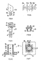
- a holding element 2 is arranged on the column side and connected by screw at four corners of the support member 2 with the support column 1.
- the holding element 2 has a base part 3, on which a holding part 4 and a holding part 4 on the base part 3 positively enclosing cap part 5 with an opening 6 through which the holding part 4 extends, is arranged. Between the base part 3 and the holding part 4, an intermediate piece 65 is included.
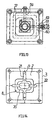
- the base part 3 shown separately in FIGS. 2 and 3 has a central recess, the bottom of which forms a sliding surface 7.
- the central recess bound four edge webs 69.
- an approximately rectangular recess 8 is provided, from the opposite longitudinal sides parts of a broken through the recess 8, extending in the sliding surface 7 guide groove 9 with a common groove axis 10 extend.
- the bottom of the recess 8 has a central opening 11.
- elongated recesses 13 and 14 are each formed with curves at both longitudinal ends.
- Holes 14 for the screw connection of the retaining element 2 to the support column 1 are formed at the four corners of the square base part 3 in the plan view.
- the cap part 5 shown separately in FIGS. 4 and 5, which is congruent with the holding part 4 in its outlines in plan view, has bores 15 at its four corners corresponding to the bores 14.
- a central recess 16 of the above-mentioned opening 6 is formed in the bottom of a central recess 16 of the above-mentioned opening 6 .
- mirror-image recesses 17 and 18 are formed to the elongated recesses.
- the intermediate piece 65 shown separately in FIGS. 6 and 7 has an approximately rectangular frame part 20 provided with an opening 19, from the opposite longitudinal sides of which a part of a sliding block 21 interrupted by the frame 20 extends with a common axis 71.
- parts of a sliding block 22 which is offset perpendicular to the frame plane, extend to the sliding block 21 and are interrupted by the opening 19, with an axis 72.
- the holding part 4 consists of a sleeve part 23 (FIG. 10 and 11), a spindle part 24 (FIG. 9) axially movable in the sleeve part 23, a spindle nut moving the spindle part 25 (Fig. 12) and an attachable to the spindle member 24 Kunststoffelelement 26 assembled for the system against a workpiece.
- the sleeve part 23 has a square base plate 27 with a sliding surface 28 which faces the sliding surface 7 of the base part 3 and bears against it.
- guide groove 29 is formed, whose longitudinal axis 30, the axis 10 of Guide groove 9 in the base part 3 in the plan view of the sliding surface 7 and 28 perpendicularly crosses.
- the bore axes are parallel to the plate plane and perpendicular to each other.
- the axis of the threaded bore 31 extends parallel to the groove longitudinal axis 30 of the guide groove 29, while the axis of the threaded bore 32 extends parallel to the groove longitudinal axis 10 of the guide groove 9 in the base part 3 itself.
- the sleeve part 23 further has a through hole 33 perpendicular to the sleeve axis for receiving a pin 34 visible in FIG.
- a longitudinal slot 35 is provided on the sleeve part 23. Perpendicular to the longitudinal slot 35 extends a tangential bore 36 for receiving a clamping screw 37 ( Figures 1 and 13). With respect to the sleeve axis of the tangential bore 36 opposite a radial bore 38 for receiving a grub screw 39 (Fig. 1) is formed.
- the spindle part 24 shown in FIG. 9 has a threaded portion 40 with an external thread. From one end of the threaded portion 40 extends a lug 41 having a radially continuous longitudinal slot 42 through which the pin 34 extends. The projection 41 is guided in guide inserts 66, which are inserted into the sleeve part 23.
- a flared cylindrical head 43 with a coaxial to the cylinder axis, ending in the head bore 44 at.
- a through hole 45 perpendicular to the cylinder axis is formed at the closed end of the bore 43 for receiving a centering pin 46 (FIG. 1).
- a radial hole 47 opening inwards to the bore 44 serves to receive a grub screw 48 (FIG. 1).
- the spindle nut 25 shown in FIG. 12 has a through hole 49 with an internal thread, which engages in the external thread on the threaded portion 40 of the spindle part 24 shown in FIG. Four provided on a head part 50 radial bores 51 serve to receive a tool used for rotation of the nut.
- radial bores 51 serve to receive a tool used for rotation of the nut.
- annular groove 53 which is formed in a shaft portion 52 of the spindle nut 25, the inner end of the grub screw 39 can engage.
- the insertable into the head piece 43 of the spindle part 25 contact element 26 has an engageable against the workpiece contact block 54 and an adjoining the contact block 54 plug-in foot 55, the free end is provided with a Zentriergabelung 56, wherein four projecting pins 57 two to each other 90 ° twisted forks are formed, which allow two correspondingly mutually rotated positions of the contact block 54.
- a Zentriergabelung 56 In each one of the forks of the centering fork 56 of the centering pin 46 engages.
- an annular groove 58 is formed for the engagement of the grub screw 48.
- the bush is slidable along a slot opening, which have been formed by the recesses 12,13 of the base part 3 and the recesses 17 and 18 of the cap part 5 when screwing the cap part 5 and the base part 3 with the support column 1.
- a connected to the socket flange stop 63 and the screw head 64 engage behind this slot opening, so that the screws 59,60 axially fixed to the support part 3.
- a threaded bushing 61a shown in Fig. 15 could be used with an internal thread and flange abutments 63a and 63a 'at both ends.
- no threaded holes are formed on the base plate 27.
- the base plate can be fixed in a displaced position by a counter to the screwing of the screw into the base part 3 screwed set screw.
- the contact element 26 is to bring within the given possibilities of variation in a desired position, wherein adjustments in three spatial directions are possible.
- the holding part 4 can be moved continuously in the plane defined by the sliding surface 7 level by means of screws 59 and 60.
- the screws can be a fine thread have, which ensures sufficient fixation in the shifted position.
- a fixation of the foot part 27 by grub screws (not shown) take place.
- spaced apart parts of the sliding blocks 21 and 22 is provided for accurate guidance and arrangement in the two spatial directions of the plane. Based on the possible displacement, these Nutensteinmaschine are designed as long as possible taking into account the stability of the intermediate piece 65 and as far as possible spaced from each other, which contributes to an accurate guidance and positioning of the holding part 4.
- Fig. 13 is a corner position and indicated by dashed lines a center position of the base plate 27.
- a stop may be formed by the frame 20 and the wall of the recess 8 or by the ends of the sliding block 21 and the ends of the groove 9. Due to the guidance in the grooves, an exact positioning and fixing of the holding part 4 is possible on the entire sliding surface 7.
- the bushes 61 move along the slot openings formed by the recesses 12 and 13 in the base part 3 and the recesses 17 and 18 in the cap part 5.
- Positional adjustments of the contact element 26 can be made by means of the spindle nut 25.
- the spindle part 24 is secured by the pin 34 against rotation in the sleeve part 23.
- the spindle part 24 is therefore displaced axially and thus changed the position of the contact block 5.
- the clamping screw 37 is actuated, wherein it allows the longitudinal slot 35 that the sleeve member 34 narrows at the respective end and the spindle nut 25 secures against further rotation and the spindle member 24 against longitudinal displacement.
- the screw 38 screwed into the bore 38 and engaging in the annular groove 53 ensures.
- the guide inserts 66 ensure accurate fixation against deflections of the contact element transversely to the spindle axis.
- the contact block 54 is held by the centering fork 56, in which the centering pin 46 engages in a precise rotational position, wherein, as already mentioned above, in the embodiment shown two rotational positions are possible.
Landscapes
- Engineering & Computer Science (AREA)
- Mechanical Engineering (AREA)
- Jigs For Machine Tools (AREA)
Claims (11)
- Elément de fixation (2) pour un dispositif destiné à fixer une pièce dans une position de référence, avec une pièce de fixation (4) pouvant être placée contre la pièce et une pièce de base (3) recevant la pièce de fixation (4), la pièce de fixation et la pièce de base présentant des surfaces de glissement (7, 28) orientées l'une vers l'autre et la pièce de fixation (4) étant parallèle au plan de la surface de glissement sur la pièce de base (3), caractérisé en ce qu'une rainure de guidage (9, 29) est réalisée dans la surface de glissement (28) de la pièce de fixation (4) ainsi que dans la surface de glissement (7) de la pièce de base (3), en ce que les axes longitudinaux (10, 30) des rainures de guidage (9, 29), vus du dessus sur le plan de glissement, se croisent et en ce qu'une pièce intermédiaire (65) pouvant être déplacée contre la pièce de fixation (4) et la pièce de base (3) est formée avec des coulisseaux (21, 22) décalés perpendiculairement par rapport au plan de glissement et disposés selon les rainures de guidage croisées (9, 29).
- Elément de fixation selon la revendication 1, caractérisé en ce qu'au moins un des coulisseaux (21, 22) présente plusieurs pièces partielles disposées à une certaine distance les unes des autres.
- Elément de fixation selon la revendication 1 ou 2, caractérisé en ce que la pièce intermédiaire (65) comprend une pièce de plaque ou de cadre (20), qui peut être déplacée dans un évidement (8) dans une (7) des deux surfaces de glissement et des pièces partielles s'étendent de la pièce de plaque et de cadre (20) sur des côtés opposés à partir d'au moins un des coulisseaux (21, 22).
- Elément de fixation selon l'une quelconque des revendications 1 à 3, caractérisé en ce que la pièce de fixation (4) peut être déplacée le long des rainures de guidage (9, 29) à l'aide de vis de réglage (59, 60), qui sont appuyées axialement contre la pièce de base (3) et qui peuvent être déplacées dans le sens perpendiculaire par rapport à l'axe de la vis.
- Elément de fixation selon la revendication 4, caractérisé en ce que les vis de réglage (59, 60 ; 65) sont à chaque fois guidées dans une douille (61 ; 61 a) qui peut être déplacée perpendiculairement à l'axe de la vis dans un trou longitudinal (12, 13 ; 17, 18) et qui présente en au moins une extrémité une bride (63 ; 63a, 63a') s'agrippant derrière le trou longitudinal.
- Elément de fixation selon l'une quelconque des revendications 1 à 5, caractérisé en ce qu'une pièce de couvercle (5) pouvant être placée sur la pièce de base (3) est pourvue d'un trou (6) derrière lequel s'agrippe la pièce de fixation (4) avec un élément de pied (27) présentant la surface de glissement (28).
- Elément de fixation selon l'une quelconque des revendications 1 à 6, caractérisé en ce que la pièce de fixation (4) présente un élément de contact (26) pouvant être placé contre la pièce dont la position peut être réglée par rapport au plan de glissement.
- Elément de fixation selon la revendication 7, caractérisé en ce que l'élément de contact (26) est lié à une tige (24) pouvant être déplacée axialement par un écrou (25) à tige pour son réglage.
- Elément de fixation selon la revendication 8, caractérisé en ce que la tige (24) est disposée de manière à ne pas pouvoir tourner dans une pièce à manchon (23) de la pièce de fixation (4) et l'écrou (25) à tige, qui est fixé axialement contre la pièce à manchon (23), s'agrippe avec un épaulement (52) à une extrémité frontale dans la pièce à manchon (23).
- Elément de fixation selon la revendication 9, caractérisé en ce que la pièce à manchon (23) présente une fente (35) et une vis de serrage (36) interagissant avec la fente (35) pour rétrécir la pièce à manchon (23) avec fixation de la tige (24) et le cas échéant de l'écrou (25) à tige sur la pièce à manchon (23).
- Elément de fixation selon l'une quelconque des revendications 7 à 10, caractérisé en ce que l'élément de contact (26) peut être placé sur le reste de la pièce de fixation (4) en plusieurs positions de rotation et présente, au niveau d'un épaulement à prise (55) une fourche de centrale (56) avec plusieurs fourchettes pouvant être placée contre une tige de centrage (46), fixant la position de rotation.
Applications Claiming Priority (2)
| Application Number | Priority Date | Filing Date | Title |
|---|---|---|---|
| DE2001157649 DE10157649A1 (de) | 2001-11-26 | 2001-11-26 | Halteelement |
| DE10157649 | 2001-11-26 |
Publications (2)
| Publication Number | Publication Date |
|---|---|
| EP1314516A1 EP1314516A1 (fr) | 2003-05-28 |
| EP1314516B1 true EP1314516B1 (fr) | 2006-02-15 |
Family
ID=7706815
Family Applications (1)
| Application Number | Title | Priority Date | Filing Date |
|---|---|---|---|
| EP20010130810 Expired - Lifetime EP1314516B1 (fr) | 2001-11-26 | 2001-12-24 | Elément de fixation |
Country Status (2)
| Country | Link |
|---|---|
| EP (1) | EP1314516B1 (fr) |
| DE (2) | DE10157649A1 (fr) |
Families Citing this family (3)
| Publication number | Priority date | Publication date | Assignee | Title |
|---|---|---|---|---|
| DE102004008624B4 (de) * | 2004-02-21 | 2008-01-24 | Daimler Ag | Aufnahmevorrichtung einer Meßeinrichtung |
| DE202005006662U1 (de) * | 2005-04-25 | 2006-08-31 | Junker & Partner Gmbh | Stützelement zum Halten eines Werkstücks, insbesondere eines Bauteils einer Fahrzeugkarosserie |
| DE202009012006U1 (de) * | 2009-09-04 | 2011-02-03 | TRUMPF Maschinen Grüsch AG | Auflagedorn zum Positionieren des Auflagedornes auf einer Werkstückauflage |
Family Cites Families (6)
| Publication number | Priority date | Publication date | Assignee | Title |
|---|---|---|---|---|
| FR2511501B1 (fr) * | 1981-08-13 | 1986-11-21 | Celette Sa | Dispositif de pince destine a etre monte sur un marbre ou banc de controle des deformations eventuelles de la carrosserie d'un vehicule |
| EP0149429B1 (fr) * | 1983-12-20 | 1991-02-06 | Büchler B-SET AG | Dispositif pour maintenir une pièce dans une position spatiale désirée |
| FR2651165A1 (fr) * | 1989-08-31 | 1991-03-01 | Celette Sa | Dispositif a pince pour le serrage du bas de caisse d'un vehicule automobile. |
| US5019129A (en) * | 1990-07-18 | 1991-05-28 | Lars Johanson | Workpiece holding system |
| JP3178978B2 (ja) * | 1994-10-24 | 2001-06-25 | 株式会社イマオコーポレーション | 取付補助部材 |
| DE10023598A1 (de) * | 2000-05-15 | 2001-11-22 | Junker & Partner Gmbh | Trägerkopf für eine Halterungsvorrichtung zur Halterung eines Werkstücks |
-
2001
- 2001-11-26 DE DE2001157649 patent/DE10157649A1/de not_active Withdrawn
- 2001-12-24 DE DE50108952T patent/DE50108952D1/de not_active Expired - Lifetime
- 2001-12-24 EP EP20010130810 patent/EP1314516B1/fr not_active Expired - Lifetime
Also Published As
| Publication number | Publication date |
|---|---|
| DE10157649A1 (de) | 2003-06-05 |
| DE50108952D1 (de) | 2006-04-20 |
| EP1314516A1 (fr) | 2003-05-28 |
Similar Documents
| Publication | Publication Date | Title |
|---|---|---|
| DE8106317U1 (de) | Bohrwerkzeug, insbesondere bohrstange | |
| DE10359052B4 (de) | Vorrichtung zum Auspressen von Bauteilen aus Achskonstruktionen | |
| EP0149429A2 (fr) | Dispositif pour maintenir une pièce dans une position spatiale désirée | |
| DD285562A5 (de) | Einstellvorrichtung, insbesondere fuer werkzeuge | |
| DE10250040A1 (de) | Reibahle und Schneidwerkzeug dafür | |
| EP0962280A2 (fr) | Dispositif d'alignement | |
| DE3634118C2 (fr) | ||
| EP1314516B1 (fr) | Elément de fixation | |
| DE19634156C1 (de) | Vorrichtung zum Handhaben einer Werkzeugmaschine | |
| WO1993004815A1 (fr) | Dispositif de serrage de pieces sur des machines a usiner ou a mesurer | |
| DE29608556U1 (de) | Spannmittel für die Verwendung an einem Werktisch | |
| DE3401200C2 (fr) | ||
| DE10023597A1 (de) | Halterungselement | |
| EP1050365B1 (fr) | Système de support pour la réception de pièces à usiner | |
| DE3432942C2 (fr) | ||
| EP0869248B1 (fr) | Charnière à montage par vissage pour des profilés avec rainure à contre-dépouille | |
| EP1714746A2 (fr) | Dispositif pour ajuster une jambe de suspension | |
| CH664312A5 (de) | Bohr- und ausdrehwerkzeug. | |
| DE10250018A1 (de) | Maschinenwerkzeug mit verstellbarer Schneide | |
| EP3091268A1 (fr) | Dispositif d'alignement de moteurs, de machines et de pieces de machines | |
| DE19827396C2 (de) | Spannvorrichtung mit verstellbarem Gegenlager | |
| DE3440527A1 (de) | Am ende eines querarms eines mess- oder anreissgeraetes befestigter mess- oder anreisskopf | |
| CH685928A5 (de) | Einrichtung zur Halterung eines Gegenstandes in einer gewunschten roumlichen Lage. | |
| DE102011111174B4 (de) | Einstellvorrichtung | |
| EP1717544B1 (fr) | Elément d'appui pour fixer une pièce à usiner |
Legal Events
| Date | Code | Title | Description |
|---|---|---|---|
| PUAI | Public reference made under article 153(3) epc to a published international application that has entered the european phase |
Free format text: ORIGINAL CODE: 0009012 |
|
| AK | Designated contracting states |
Designated state(s): AT BE CH CY DE DK ES FI FR GB GR IE IT LI LU MC NL PT SE TR |
|
| AX | Request for extension of the european patent |
Extension state: AL LT LV MK RO SI |
|
| 17P | Request for examination filed |
Effective date: 20031017 |
|
| AKX | Designation fees paid |
Designated state(s): DE ES FR GB IT |
|
| 17Q | First examination report despatched |
Effective date: 20041029 |
|
| GRAP | Despatch of communication of intention to grant a patent |
Free format text: ORIGINAL CODE: EPIDOSNIGR1 |
|
| GRAS | Grant fee paid |
Free format text: ORIGINAL CODE: EPIDOSNIGR3 |
|
| GRAA | (expected) grant |
Free format text: ORIGINAL CODE: 0009210 |
|
| AK | Designated contracting states |
Kind code of ref document: B1 Designated state(s): DE ES FR GB IT |
|
| PG25 | Lapsed in a contracting state [announced via postgrant information from national office to epo] |
Ref country code: IT Free format text: LAPSE BECAUSE OF FAILURE TO SUBMIT A TRANSLATION OF THE DESCRIPTION OR TO PAY THE FEE WITHIN THE PRESCRIBED TIME-LIMIT;WARNING: LAPSES OF ITALIAN PATENTS WITH EFFECTIVE DATE BEFORE 2007 MAY HAVE OCCURRED AT ANY TIME BEFORE 2007. THE CORRECT EFFECTIVE DATE MAY BE DIFFERENT FROM THE ONE RECORDED. Effective date: 20060215 Ref country code: GB Free format text: LAPSE BECAUSE OF FAILURE TO SUBMIT A TRANSLATION OF THE DESCRIPTION OR TO PAY THE FEE WITHIN THE PRESCRIBED TIME-LIMIT Effective date: 20060215 |
|
| REG | Reference to a national code |
Ref country code: GB Ref legal event code: FG4D Free format text: NOT ENGLISH |
|
| REF | Corresponds to: |
Ref document number: 50108952 Country of ref document: DE Date of ref document: 20060420 Kind code of ref document: P |
|
| PG25 | Lapsed in a contracting state [announced via postgrant information from national office to epo] |
Ref country code: ES Free format text: LAPSE BECAUSE OF FAILURE TO SUBMIT A TRANSLATION OF THE DESCRIPTION OR TO PAY THE FEE WITHIN THE PRESCRIBED TIME-LIMIT Effective date: 20060526 |
|
| GBV | Gb: ep patent (uk) treated as always having been void in accordance with gb section 77(7)/1977 [no translation filed] |
Effective date: 20060215 |
|
| PLBE | No opposition filed within time limit |
Free format text: ORIGINAL CODE: 0009261 |
|
| STAA | Information on the status of an ep patent application or granted ep patent |
Free format text: STATUS: NO OPPOSITION FILED WITHIN TIME LIMIT |
|
| 26N | No opposition filed |
Effective date: 20061116 |
|
| EN | Fr: translation not filed | ||
| PG25 | Lapsed in a contracting state [announced via postgrant information from national office to epo] |
Ref country code: FR Free format text: LAPSE BECAUSE OF FAILURE TO SUBMIT A TRANSLATION OF THE DESCRIPTION OR TO PAY THE FEE WITHIN THE PRESCRIBED TIME-LIMIT Effective date: 20070105 |
|
| PG25 | Lapsed in a contracting state [announced via postgrant information from national office to epo] |
Ref country code: FR Free format text: LAPSE BECAUSE OF FAILURE TO SUBMIT A TRANSLATION OF THE DESCRIPTION OR TO PAY THE FEE WITHIN THE PRESCRIBED TIME-LIMIT Effective date: 20060215 |
|
| REG | Reference to a national code |
Ref country code: DE Ref legal event code: R081 Ref document number: 50108952 Country of ref document: DE Owner name: CARL ZEISS FIXTURE SYSTEMS GMBH, DE Free format text: FORMER OWNER: JUNKER & PARTNER GMBH, 66636 THOLEY, DE Effective date: 20131024 Ref country code: DE Ref legal event code: R082 Ref document number: 50108952 Country of ref document: DE Representative=s name: PATENTANWAELTE DR.-ING. W. BERNHARDT DR. R. BE, DE Effective date: 20131024 Ref country code: DE Ref legal event code: R082 Ref document number: 50108952 Country of ref document: DE Representative=s name: PATENTANWAELTE BERNHARDT/WOLFF PARTNERSCHAFT, DE Effective date: 20131024 Ref country code: DE Ref legal event code: R082 Ref document number: 50108952 Country of ref document: DE Representative=s name: PATENTANWAELTE BERNHARDT/WOLFF PARTNERSCHAFT M, DE Effective date: 20131024 |
|
| REG | Reference to a national code |
Ref country code: DE Ref legal event code: R082 Ref document number: 50108952 Country of ref document: DE Representative=s name: PATENTANWAELTE BERNHARDT/WOLFF PARTNERSCHAFT, DE Ref country code: DE Ref legal event code: R082 Ref document number: 50108952 Country of ref document: DE Representative=s name: PATENTANWAELTE BERNHARDT/WOLFF PARTNERSCHAFT M, DE |
|
| PGFP | Annual fee paid to national office [announced via postgrant information from national office to epo] |
Ref country code: DE Payment date: 20191128 Year of fee payment: 19 |
|
| REG | Reference to a national code |
Ref country code: DE Ref legal event code: R119 Ref document number: 50108952 Country of ref document: DE |
|
| PG25 | Lapsed in a contracting state [announced via postgrant information from national office to epo] |
Ref country code: DE Free format text: LAPSE BECAUSE OF NON-PAYMENT OF DUE FEES Effective date: 20210701 |