EP1314536A1 - Vorrichtung zum Formen und Ausstanzen von Behältern aus einer Folienbahn aus thermoplastischem Kunststoff - Google Patents
Vorrichtung zum Formen und Ausstanzen von Behältern aus einer Folienbahn aus thermoplastischem Kunststoff Download PDFInfo
- Publication number
- EP1314536A1 EP1314536A1 EP02025299A EP02025299A EP1314536A1 EP 1314536 A1 EP1314536 A1 EP 1314536A1 EP 02025299 A EP02025299 A EP 02025299A EP 02025299 A EP02025299 A EP 02025299A EP 1314536 A1 EP1314536 A1 EP 1314536A1
- Authority
- EP
- European Patent Office
- Prior art keywords
- lower table
- bridge
- stacking
- film web
- articles
- Prior art date
- Legal status (The legal status is an assumption and is not a legal conclusion. Google has not performed a legal analysis and makes no representation as to the accuracy of the status listed.)
- Granted
Links
Images

Classifications
-
- B—PERFORMING OPERATIONS; TRANSPORTING
- B29—WORKING OF PLASTICS; WORKING OF SUBSTANCES IN A PLASTIC STATE IN GENERAL
- B29C—SHAPING OR JOINING OF PLASTICS; SHAPING OF MATERIAL IN A PLASTIC STATE, NOT OTHERWISE PROVIDED FOR; AFTER-TREATMENT OF THE SHAPED PRODUCTS, e.g. REPAIRING
- B29C51/00—Shaping by thermoforming, i.e. shaping sheets or sheet like preforms after heating, e.g. shaping sheets in matched moulds or by deep-drawing; Apparatus therefor
- B29C51/26—Component parts, details or accessories; Auxiliary operations
- B29C51/30—Moulds
- B29C51/38—Opening, closing or clamping means
-
- B—PERFORMING OPERATIONS; TRANSPORTING
- B29—WORKING OF PLASTICS; WORKING OF SUBSTANCES IN A PLASTIC STATE IN GENERAL
- B29C—SHAPING OR JOINING OF PLASTICS; SHAPING OF MATERIAL IN A PLASTIC STATE, NOT OTHERWISE PROVIDED FOR; AFTER-TREATMENT OF THE SHAPED PRODUCTS, e.g. REPAIRING
- B29C51/00—Shaping by thermoforming, i.e. shaping sheets or sheet like preforms after heating, e.g. shaping sheets in matched moulds or by deep-drawing; Apparatus therefor
- B29C51/04—Combined thermoforming and prestretching, e.g. biaxial stretching
-
- B—PERFORMING OPERATIONS; TRANSPORTING
- B29—WORKING OF PLASTICS; WORKING OF SUBSTANCES IN A PLASTIC STATE IN GENERAL
- B29C—SHAPING OR JOINING OF PLASTICS; SHAPING OF MATERIAL IN A PLASTIC STATE, NOT OTHERWISE PROVIDED FOR; AFTER-TREATMENT OF THE SHAPED PRODUCTS, e.g. REPAIRING
- B29C51/00—Shaping by thermoforming, i.e. shaping sheets or sheet like preforms after heating, e.g. shaping sheets in matched moulds or by deep-drawing; Apparatus therefor
- B29C51/26—Component parts, details or accessories; Auxiliary operations
- B29C51/44—Removing or ejecting moulded articles
Definitions
- the invention relates to a device for molding and punching out containers from a sheet of thermoplastic material according to the genus of Main claim.
- a device with a combined forming and punching molding station in which the lower table, which carries the lower part with the shaping parts of the shaping / punching tool, after shaping and punching out the container by an angle between Is pivoted 30 and 90 °.
- the containers are transferred from the lower part into stacking magazines or to a stacking device.
- the lower table is also axially displaceable, so that the upper part of the shaping / punching tool fastened to the upper table can be arranged in a stationary manner with the cutting plate and possibly with stretching aids.
- the invention has for its object to design the device so that a high closing force with low load on the drive elements in the Form position is given via a toggle lever drive and a movement of the Under table when approaching the stacking position in the direction of the stacking magazines takes place so that they can be arranged in a fixed position and still only one short distance when stacking must be bridged.
- a collision risk at no time should there be between the under table and the stacking magazines.
- the device consists of a forming station 18, a transport device 2 for the intermittent transport of a horizontally moving film web 19 through the device and a heating device 1 if this film web 19 is unwound from a roll 20. If the film web 19 is fed directly from an extruder, this heating device 1 may be dispensed with.
- the forming station 18 consists of a stationary upper table 3, to which the upper part 4 of a combined forming / punching tool is attached. This upper part 4 has a cutting plate and, if necessary, stretching aids for mechanically pre-stretching the film web 19. Furthermore, from the vertically movable and pivotable lower table 5, on which the lower part 6 of the shaping / punching tool is fastened with the shaping and punching components.
- the lower table 5 is pivoted by the drive device designated 22 in the form of a cam drive either transversely to the direction of travel of the film web 19, which is represented by the arrow 24. Swiveling in the direction of travel of the film web 19 is possible in the same way with the drive device 22 arranged rotated by 90 °.
- the drive device 22 is described in more detail below.
- the lower table 5 is guided over guide rails 8 which are mounted in the swivel bridge 9.
- the swivel bridge 9 is mounted in the pivot point 10, which can also be the pivot point for the lower toggle link plates 11, as shown. Depending on the geometric conditions, an offset pivot point may be cheaper.
- This push rod 13 is connected to the pivotable lever 14, which is moved between the positions in FIGS. 1 and 2 via a cam, not shown.
- the height shift of the lower table 5 takes place via the toggle lever brackets 11, 23 forming a toggle lever from the cams 15 from the pivoting levers 26, 27 and via the push rod 25 which is articulated on the toggle lever brackets 11, 23.
- the molded parts 17 are pushed into the stacking device 7 via a pneumatic or cam-operated ejector device after the end position of the lower table 5 has been reached.
- the backward movement of the lower table 5 into the forming / punching position takes place in the reverse order.
- the drive device 22 can also be designed in such a way that the two push rods 13, 25 are each moved via a crank mechanism, which by is driven by a servo motor.
- a drive is from DE 40 33 534 A1 known.
Landscapes
- Engineering & Computer Science (AREA)
- Mechanical Engineering (AREA)
- Blow-Moulding Or Thermoforming Of Plastics Or The Like (AREA)
- Perforating, Stamping-Out Or Severing By Means Other Than Cutting (AREA)
- Containers And Plastic Fillers For Packaging (AREA)
Abstract
Description
Nachteilig bei dieser Ausführung ist es, dass - bedingt durch die vertikale Führung der Führungsteile, in denen der Untertisch drehbar gelagert ist - am Ende der Schwenkbewegung in Stapelstellung keine Verschiebung des Untertisches in Richtung der Stapelmagazine möglich ist. Wegen des Schwenkradius des Unterteils des Form-/Stanzwerkzeuges ist ein entsprechender Abstand zu einem ortsfesten Stapelmagazinen erforderlich, der Störungen bei der Übergabe von insbesondere flachen Teilen wie Deckeln verursacht. Dem kann durch eine Verschiebung der Stapelmagazine in Richtung Untertisch begegnet werden, was aber einen zweiten Antrieb erfordert und Synchronisationsprobleme mit sich bringt. Eine Kollision zwischen Unterteil und Stapelmagazinen an dieser Stelle hat schwerwiegende und teuere Folgen.
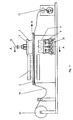
- Fig. 1
- eine Seitenansicht der Vorrichtung.
- Fig. 2
- einen Querschnitt entlang der Linie A - A in Figur 1 durch die Formstation bei geschlossenem Werkzeug.
- Fig. 3
- denselben Querschnitt durch die Formstation bei geschwenkter unterer Werkzeughälfte.
Die Formstation 18 besteht aus einem ortsfesten Obertisch 3, an dem das Oberteil 4 eines kombinierten Form-/Stanzwerkzeuges befestigt ist. Dieses Oberteil 4 weist eine Schnittplatte und bei Bedarf Streckhelfer zum mechanischen Vorstrecken der Folienbahn 19 auf. Ferner aus dem höhenbeweglichen und schwenkbaren Untertisch 5, an dem das Untereil 6 des Form-/Stanzwerkzeuges mit den formgebenden und stanzenden Bauteilen befestigt ist.
Das Schwenken des Untertisches 5 erfolgt durch die mit Position 22 bezeichnete Antriebseinrichtung in Form eines Kurventriebs entweder quer zur Durchlaufrichtung der Folienbahn 19, die durch den Pfeil 24 dargestellt ist. Ein Schwenken in Durchlaufrichtung der Folienbahn 19 ist in gleicher Weise bei um 90° gedreht angeordneter Antriebseinrichtung 22 möglich.
Nach einem Stop der Bewegung der Schubstange 25 und damit der unteren Kniehebellasche 11 durch eine entsprechende Gestaltung der Kurvenscheibe 15 entsteht beim Weiterschwenken des Untertisches 5 über die Schubstange 13 eine Schubbewegung auf die Unterbrücke 5 in Richtung Stapelmagazin 7. Durch eine entsprechende Gestaltung der Kurvenscheibe 15 kann zusätzlich ein Rückwärtsschwenken der unteren Kniehebellaschen 11 bis in Strecklage der beiden Kniehebellaschen 11, 23 über die Schubstange 25 und somit eine zusätzliche Schubbewegung des Untertisches 5 in Richtung der Stapelmagazine 7 erreicht werden. Während dieser Rückwärtsbewegung steht die Schubstange 13. Es wird dadurch eine sichere Übergabe der Formteile 17 in die Stapelvorrichtung 7 ermöglicht.
Die Formteile 17 werden nach Erreichen der Endlage des Untertisches 5 über eine pneumatisch- oder kurvenbetätigte Auswerfereinrichtung in die Stapeleinrichtung 7 gestoßen. Die Rückwärtsbewegung des Untertisches 5 in die Form-/Stanzposition erfolgt in umgekehrter Reihenfolge.
Claims (7)
- Vorrichtung zum Formen und Ausstanzen von Behältern (17) aus einer Folienbahn (19) aus thermoplastischem Kunststoff, mit einer intermittierenden Transporteinrichtung (2) zum horizontalen Führen der Folienbahn (19), mit einem oberhalb der Folienbahn (19) angeordneten Obertisch (3) zur Aufnahme des Oberteils (4) und einem unterhalb der Folienbahn (19) angeordneten höhenverschiebbaren und schwenkbaren Untertisch (5) zur Aufnahme des Unterteils (6) eines kombinierten Form-/Stanzwerkzeuges, wobei der Untertisch (5) an einer um einen Drehpunkt (10) schwenkbaren Schwenkbrücke (9) verschiebbar geführt ist, dadurch gekennzeichnet, dass der Untertisch (5) über Kniehebellaschen (11, 23) an der Schwenkbrücke (9) gehalten ist, die über eine erste Schubstange (25) von einer seitlich angeordneten Antriebseinrichtung (22) aus bewegt werden, wobei die Antriebseinrichtung (22) über eine zweite Schubstange (13) auch die Schwenkbewegung der Schwenkbrücke (9) bewirkt.
- Vorrichtung nach Anspruch 1, dadurch gekennzeichnet, dass der Untertisch (5) über Führungssäulen (8) zur Schwenkbrücke (9) geführt ist.
- Vorrichtung nach Anspruch 1 oder 2, dadurch gekennzeichnet, dass die Schwenkbrücke (9) und die unteren Kniehebellaschen (11) im gleichen Drehpunkt (10) gelagert sind.
- Vorrichtung nach Anspruch 1 oder 2, dadurch gekennzeichnet, dass die Schwenkbrücke (9) und die unteren Kniehebellaschen (11) in zueinander versetzten Drehpunkten gelagert sind.
- Vorrichtung nach einem der Ansprüche 1 bis 4, dadurch gekennzeichnet, dass die Antriebseinrichtung (22) kurvenbetätigt ist.
- Vorrichtung nach einem der Ansprüche 1 bis 5, dadurch gekennzeichnet, dass die Antriebseinrichtung (22) zum Bewegen der Kniehebellaschen (11, 23) so gestaltet ist, dass diese beim oder nach dem Schwenken des Untertisches (5) in Stapellage in Strecklage gebracht werden.
- Vorrichtung nach einem der Ansprüche 1 bis 6, dadurch gekennzeichnet, dass der Schwenkwinkel des Untertisches (5) zwischen 20° und 50° liegt.
Applications Claiming Priority (2)
| Application Number | Priority Date | Filing Date | Title |
|---|---|---|---|
| DE10157134 | 2001-11-21 | ||
| DE10157134A DE10157134B4 (de) | 2001-11-21 | 2001-11-21 | Vorrichtung zum Formen und Ausstanzen von Behältern aus einer Folienbahn aus thermoplastischem Kunststoff |
Publications (2)
| Publication Number | Publication Date |
|---|---|
| EP1314536A1 true EP1314536A1 (de) | 2003-05-28 |
| EP1314536B1 EP1314536B1 (de) | 2004-04-28 |
Family
ID=7706465
Family Applications (1)
| Application Number | Title | Priority Date | Filing Date |
|---|---|---|---|
| EP02025299A Expired - Lifetime EP1314536B1 (de) | 2001-11-21 | 2002-11-13 | Vorrichtung zum Formen und Ausstanzen von Behältern aus einer Folienbahn aus thermoplastischem Kunststoff |
Country Status (4)
| Country | Link |
|---|---|
| EP (1) | EP1314536B1 (de) |
| AT (1) | ATE265308T1 (de) |
| DE (2) | DE10157134B4 (de) |
| DK (1) | DK1314536T3 (de) |
Cited By (4)
| Publication number | Priority date | Publication date | Assignee | Title |
|---|---|---|---|---|
| WO2003099541A1 (de) * | 2002-04-25 | 2003-12-04 | Kuhne Anlagenbau Gmbh | Thermoformanlage zur herstellung von formkörpern aus kunststoffolie, sowie verfahren zu deren herstellung |
| RU2291054C2 (ru) * | 2002-04-25 | 2007-01-10 | Куне Анлагенбау Гмбх | Термоформовочная установка для изготовления формованных изделий из полимерной пленки, а также способ их изготовления |
| EP1982822A1 (de) * | 2007-04-16 | 2008-10-22 | T.F.T. S.R.L. | Gerät zur Bildung eines Formnestes für eine Presse, insbesondere zur Herstellung von Kunststoffartikeln |
| EP2143550A1 (de) | 2008-07-11 | 2010-01-13 | Gabler Thermoform GmbH & Co. KG | Vorrichtung zum Herstellen von Hohlkörpern aus thermoplastisch verformbaren Kunststoff-Folien |
Families Citing this family (1)
| Publication number | Priority date | Publication date | Assignee | Title |
|---|---|---|---|---|
| DE102004019682B4 (de) | 2004-04-23 | 2008-09-18 | Gabler Thermoform Gmbh & Co. Kg | Verfahren zum Betreiben einer Thermoformmaschine und Thermoformmaschine |
Citations (5)
| Publication number | Priority date | Publication date | Assignee | Title |
|---|---|---|---|---|
| DE3346628A1 (de) * | 1983-12-23 | 1985-07-11 | Adolf Illig Maschinenbau Gmbh & Co, 7100 Heilbronn | Vorrichtung zum formen, stanzen und stapeln von teilen aus thermoplastischer kunststoffolie |
| DE3601937A1 (de) * | 1986-01-23 | 1987-07-30 | Illig Maschinenbau Adolf | Vorrichtung zum herstellen von tiefziehteilen |
| DE9108344U1 (de) * | 1991-07-06 | 1991-08-29 | Maschinenbau Gabler GmbH, 2400 Lübeck | Vorrichtung zum Formen, Stanzen und Stapeln von tiergezogenen Teilen aus thermoplastischem Kunststoffmaterial |
| DE19710475A1 (de) * | 1997-03-13 | 1998-09-17 | Kuhne Anlagenbau Gmbh | Vorrichtung zur Herstellung von Hohlkörpern aus thermoplastisch verformbaren Kunststoff-Folien |
| US6135756A (en) * | 1997-06-13 | 2000-10-24 | Arends; Albert W. | Differential pressure forming, trimming and stacking apparatus |
Family Cites Families (2)
| Publication number | Priority date | Publication date | Assignee | Title |
|---|---|---|---|---|
| DE4033534C2 (de) * | 1990-10-22 | 1999-06-10 | Illig Maschinenbau Adolf | Vorrichtung zum Formen, Stanzen und Stapeln von tiefgezogenen Teilen aus thermoplastischem Kunststoff |
| DE19716655C2 (de) * | 1997-04-21 | 2002-11-21 | Gabler Gmbh Maschbau | Vorrichtung zum Formen, Stanzen und Stapeln von tiefgezogenen Teilen aus thermoplastischem Kunststoff |
-
2001
- 2001-11-21 DE DE10157134A patent/DE10157134B4/de not_active Expired - Fee Related
-
2002
- 2002-11-13 EP EP02025299A patent/EP1314536B1/de not_active Expired - Lifetime
- 2002-11-13 DE DE50200393T patent/DE50200393D1/de not_active Expired - Lifetime
- 2002-11-13 AT AT02025299T patent/ATE265308T1/de active
- 2002-11-13 DK DK02025299T patent/DK1314536T3/da active
Patent Citations (5)
| Publication number | Priority date | Publication date | Assignee | Title |
|---|---|---|---|---|
| DE3346628A1 (de) * | 1983-12-23 | 1985-07-11 | Adolf Illig Maschinenbau Gmbh & Co, 7100 Heilbronn | Vorrichtung zum formen, stanzen und stapeln von teilen aus thermoplastischer kunststoffolie |
| DE3601937A1 (de) * | 1986-01-23 | 1987-07-30 | Illig Maschinenbau Adolf | Vorrichtung zum herstellen von tiefziehteilen |
| DE9108344U1 (de) * | 1991-07-06 | 1991-08-29 | Maschinenbau Gabler GmbH, 2400 Lübeck | Vorrichtung zum Formen, Stanzen und Stapeln von tiergezogenen Teilen aus thermoplastischem Kunststoffmaterial |
| DE19710475A1 (de) * | 1997-03-13 | 1998-09-17 | Kuhne Anlagenbau Gmbh | Vorrichtung zur Herstellung von Hohlkörpern aus thermoplastisch verformbaren Kunststoff-Folien |
| US6135756A (en) * | 1997-06-13 | 2000-10-24 | Arends; Albert W. | Differential pressure forming, trimming and stacking apparatus |
Cited By (6)
| Publication number | Priority date | Publication date | Assignee | Title |
|---|---|---|---|---|
| WO2003099541A1 (de) * | 2002-04-25 | 2003-12-04 | Kuhne Anlagenbau Gmbh | Thermoformanlage zur herstellung von formkörpern aus kunststoffolie, sowie verfahren zu deren herstellung |
| RU2291054C2 (ru) * | 2002-04-25 | 2007-01-10 | Куне Анлагенбау Гмбх | Термоформовочная установка для изготовления формованных изделий из полимерной пленки, а также способ их изготовления |
| US7560063B2 (en) | 2002-04-25 | 2009-07-14 | Kuhne Anlagenbau Gmbh | Thermoforming installation for producing shaped bodies made of plastic film, and method for producing the same |
| EP1982822A1 (de) * | 2007-04-16 | 2008-10-22 | T.F.T. S.R.L. | Gerät zur Bildung eines Formnestes für eine Presse, insbesondere zur Herstellung von Kunststoffartikeln |
| EP2143550A1 (de) | 2008-07-11 | 2010-01-13 | Gabler Thermoform GmbH & Co. KG | Vorrichtung zum Herstellen von Hohlkörpern aus thermoplastisch verformbaren Kunststoff-Folien |
| US8105069B2 (en) | 2008-07-11 | 2012-01-31 | Gambler Thermoform GmbH & Co. KG | Apparatus for making hollow bodies from thermoplastic film |
Also Published As
| Publication number | Publication date |
|---|---|
| DE50200393D1 (de) | 2004-06-03 |
| ATE265308T1 (de) | 2004-05-15 |
| DE10157134B4 (de) | 2005-07-07 |
| EP1314536B1 (de) | 2004-04-28 |
| DK1314536T3 (da) | 2004-07-26 |
| DE10157134A1 (de) | 2003-05-28 |
Similar Documents
| Publication | Publication Date | Title |
|---|---|---|
| DE2439722C3 (de) | Bewegungsgetriebe für ein Arbeitsorgan | |
| DE102007049168B4 (de) | Vorrichtung und Verfahren zum Verschieben von aus erwärmten thermoplastischen Halbzeugen geformten und ausgestanzten Tiefziehprodukten von einer Thermoformmaschine zu einer Verarbeitungsstation | |
| DE69005021T2 (de) | Schwenkbare Werkstück-Entnahmevorrichtung. | |
| DE2100426C3 (de) | Fördereinrichtung für den kontinuierlichen Transport von vorgeformten Faltbehältern mit rechteckigem Boden durch die Füll- und Verschließstationen einer Verpackungsmaschine | |
| DE3346628C2 (de) | Vorrichtung zum Formen, Stanzen und Stapeln von tiefgezogenen Teilen aus thermoplastischem Kunststoff | |
| DE102004027949B4 (de) | Vorrichtung zum Herstellen eines Bandes von etikettierten Behältern aus einer erwärmten thermoplastischen Kunststofffolie | |
| DE2256180A1 (de) | Auf eine presse montierbare einrichtung zum lochen | |
| EP2143550B1 (de) | Vorrichtung zum Herstellen von Hohlkörpern aus thermoplastisch verformbaren Kunststoff-Folien | |
| AT403777B (de) | Formschliessvorrichtung | |
| EP1052080B1 (de) | Verfahren zum Bewegen eines Schwenktisches in einer Vorrichtung zum Formen und Ausstanzen von Behältern aus einer thermoplastischen Kunststofffolie und Vorrichtung zur Durchführung des Verfahrens | |
| EP1221365B1 (de) | Kombinierte Form-/Stanzstation zum Formen und Ausstanzen von Behältern aus einer Folienbahn aus thermoplastischem Kunststoff | |
| EP0499676A1 (de) | Verfahren zum Einlegen einer Hüllfolie in eine Formhälfte eines Werkzeuges einer Spritzgussmaschine | |
| DE69106268T2 (de) | Vorrichtung zum Drehen einer Platte oder eines Pakets von Platten auf einem Arbeitstisch von einer Schneidmaschine. | |
| DE4005948A1 (de) | Buchbindemaschine zum rueckenrunden von buchblocks | |
| EP1314536B1 (de) | Vorrichtung zum Formen und Ausstanzen von Behältern aus einer Folienbahn aus thermoplastischem Kunststoff | |
| DE69607116T2 (de) | Vorrichtung zum Entfernen von Produkten aus einer Spritzgiessform | |
| EP0392047B1 (de) | Verfahren und Vorrichtung zum Heissverformen einer Kunstharz-Schichtpressstoffplatte | |
| EP0294582A2 (de) | Vorrichtung zum Herstellen von Beuteln oder Säcken aus einer vorzugsweise mit Seitenfalten versehenen Schlauchfolienbahn aus thermoplastischem Kunststoff | |
| DE2020401A1 (de) | Vorrichtung zum Warmverformen von Kunststoff-Folien od.dgl. | |
| DE7512275U (de) | Antriebsvorrichtung fuer einen bogeneinleger | |
| DE19742107B4 (de) | Vorrichtung zum Formen, Stanzen und Stapeln von Behältern aus einer Folienbahn aus thermoplastischem Kunststoff | |
| DE102007035437B3 (de) | Schwenkbare Transportvorrichtung für Flachmaterialstücke | |
| DE20119020U1 (de) | Vorrichtung zum Formen und Ausstanzen von Behältern aus einer Folienbahn aus thermoplastischem Kunststoff | |
| EP1025978B1 (de) | Vorrichtung zum Thermoformen von Behältern aus einer Folienbahn aus thermoplastischem Kunststoff | |
| DE2253234A1 (de) | Verfahren und vorrichtung zur blasformung plastischer gegenstaende |
Legal Events
| Date | Code | Title | Description |
|---|---|---|---|
| PUAI | Public reference made under article 153(3) epc to a published international application that has entered the european phase |
Free format text: ORIGINAL CODE: 0009012 |
|
| 17P | Request for examination filed |
Effective date: 20030304 |
|
| AK | Designated contracting states |
Designated state(s): AT BE BG CH CY CZ DE DK EE ES FI FR GB GR IE IT LI LU MC NL PT SE SK TR |
|
| AX | Request for extension of the european patent |
Extension state: AL LT LV MK RO SI |
|
| GRAP | Despatch of communication of intention to grant a patent |
Free format text: ORIGINAL CODE: EPIDOSNIGR1 |
|
| GRAS | Grant fee paid |
Free format text: ORIGINAL CODE: EPIDOSNIGR3 |
|
| AKX | Designation fees paid |
Designated state(s): AT BE BG CH CY CZ DE DK EE ES FI FR GB GR IE IT LI LU MC NL PT SE SK TR |
|
| GRAA | (expected) grant |
Free format text: ORIGINAL CODE: 0009210 |
|
| AK | Designated contracting states |
Kind code of ref document: B1 Designated state(s): AT BE BG CH CY CZ DE DK EE ES FI FR GB GR IE IT LI LU MC NL PT SE SK TR |
|
| PG25 | Lapsed in a contracting state [announced via postgrant information from national office to epo] |
Ref country code: BG Free format text: LAPSE BECAUSE OF FAILURE TO SUBMIT A TRANSLATION OF THE DESCRIPTION OR TO PAY THE FEE WITHIN THE PRESCRIBED TIME-LIMIT Effective date: 20040428 Ref country code: EE Free format text: LAPSE BECAUSE OF FAILURE TO SUBMIT A TRANSLATION OF THE DESCRIPTION OR TO PAY THE FEE WITHIN THE PRESCRIBED TIME-LIMIT Effective date: 20040428 Ref country code: FI Free format text: LAPSE BECAUSE OF FAILURE TO SUBMIT A TRANSLATION OF THE DESCRIPTION OR TO PAY THE FEE WITHIN THE PRESCRIBED TIME-LIMIT Effective date: 20040428 Ref country code: CY Free format text: LAPSE BECAUSE OF FAILURE TO SUBMIT A TRANSLATION OF THE DESCRIPTION OR TO PAY THE FEE WITHIN THE PRESCRIBED TIME-LIMIT Effective date: 20040428 Ref country code: CZ Free format text: LAPSE BECAUSE OF FAILURE TO SUBMIT A TRANSLATION OF THE DESCRIPTION OR TO PAY THE FEE WITHIN THE PRESCRIBED TIME-LIMIT Effective date: 20040428 Ref country code: SK Free format text: LAPSE BECAUSE OF FAILURE TO SUBMIT A TRANSLATION OF THE DESCRIPTION OR TO PAY THE FEE WITHIN THE PRESCRIBED TIME-LIMIT Effective date: 20040428 Ref country code: TR Free format text: LAPSE BECAUSE OF FAILURE TO SUBMIT A TRANSLATION OF THE DESCRIPTION OR TO PAY THE FEE WITHIN THE PRESCRIBED TIME-LIMIT Effective date: 20040428 Ref country code: NL Free format text: LAPSE BECAUSE OF FAILURE TO SUBMIT A TRANSLATION OF THE DESCRIPTION OR TO PAY THE FEE WITHIN THE PRESCRIBED TIME-LIMIT Effective date: 20040428 Ref country code: FR Free format text: LAPSE BECAUSE OF FAILURE TO SUBMIT A TRANSLATION OF THE DESCRIPTION OR TO PAY THE FEE WITHIN THE PRESCRIBED TIME-LIMIT Effective date: 20040428 Ref country code: IE Free format text: LAPSE BECAUSE OF FAILURE TO SUBMIT A TRANSLATION OF THE DESCRIPTION OR TO PAY THE FEE WITHIN THE PRESCRIBED TIME-LIMIT Effective date: 20040428 |
|
| REG | Reference to a national code |
Ref country code: GB Ref legal event code: FG4D Free format text: NOT ENGLISH |
|
| REG | Reference to a national code |
Ref country code: CH Ref legal event code: EP |
|
| REG | Reference to a national code |
Ref country code: IE Ref legal event code: FG4D Free format text: GERMAN |
|
| REF | Corresponds to: |
Ref document number: 50200393 Country of ref document: DE Date of ref document: 20040603 Kind code of ref document: P |
|
| REG | Reference to a national code |
Ref country code: DK Ref legal event code: T3 |
|
| PG25 | Lapsed in a contracting state [announced via postgrant information from national office to epo] |
Ref country code: SE Free format text: LAPSE BECAUSE OF FAILURE TO SUBMIT A TRANSLATION OF THE DESCRIPTION OR TO PAY THE FEE WITHIN THE PRESCRIBED TIME-LIMIT Effective date: 20040728 Ref country code: GR Free format text: LAPSE BECAUSE OF FAILURE TO SUBMIT A TRANSLATION OF THE DESCRIPTION OR TO PAY THE FEE WITHIN THE PRESCRIBED TIME-LIMIT Effective date: 20040728 |
|
| PG25 | Lapsed in a contracting state [announced via postgrant information from national office to epo] |
Ref country code: ES Free format text: LAPSE BECAUSE OF FAILURE TO SUBMIT A TRANSLATION OF THE DESCRIPTION OR TO PAY THE FEE WITHIN THE PRESCRIBED TIME-LIMIT Effective date: 20040808 |
|
| GBT | Gb: translation of ep patent filed (gb section 77(6)(a)/1977) |
Effective date: 20040806 |
|
| NLV1 | Nl: lapsed or annulled due to failure to fulfill the requirements of art. 29p and 29m of the patents act | ||
| PG25 | Lapsed in a contracting state [announced via postgrant information from national office to epo] |
Ref country code: LU Free format text: LAPSE BECAUSE OF NON-PAYMENT OF DUE FEES Effective date: 20041113 |
|
| PG25 | Lapsed in a contracting state [announced via postgrant information from national office to epo] |
Ref country code: BE Free format text: LAPSE BECAUSE OF NON-PAYMENT OF DUE FEES Effective date: 20041130 Ref country code: MC Free format text: LAPSE BECAUSE OF NON-PAYMENT OF DUE FEES Effective date: 20041130 |
|
| REG | Reference to a national code |
Ref country code: IE Ref legal event code: FD4D |
|
| PLBE | No opposition filed within time limit |
Free format text: ORIGINAL CODE: 0009261 |
|
| STAA | Information on the status of an ep patent application or granted ep patent |
Free format text: STATUS: NO OPPOSITION FILED WITHIN TIME LIMIT |
|
| EN | Fr: translation not filed | ||
| 26N | No opposition filed |
Effective date: 20050131 |
|
| BERE | Be: lapsed |
Owner name: ADOLF *ILLIG MASCHINENBAU G.M.B.H. & CO. K.G. Effective date: 20041130 |
|
| PG25 | Lapsed in a contracting state [announced via postgrant information from national office to epo] |
Ref country code: CH Free format text: LAPSE BECAUSE OF NON-PAYMENT OF DUE FEES Effective date: 20061130 Ref country code: LI Free format text: LAPSE BECAUSE OF NON-PAYMENT OF DUE FEES Effective date: 20061130 |
|
| REG | Reference to a national code |
Ref country code: CH Ref legal event code: PL |
|
| BERE | Be: lapsed |
Owner name: ADOLF *ILLIG MASCHINENBAU G.M.B.H. & CO. K.G. Effective date: 20041130 |
|
| PG25 | Lapsed in a contracting state [announced via postgrant information from national office to epo] |
Ref country code: PT Free format text: LAPSE BECAUSE OF NON-PAYMENT OF DUE FEES Effective date: 20040928 |
|
| PGFP | Annual fee paid to national office [announced via postgrant information from national office to epo] |
Ref country code: AT Payment date: 20101119 Year of fee payment: 9 |
|
| PGFP | Annual fee paid to national office [announced via postgrant information from national office to epo] |
Ref country code: IT Payment date: 20101127 Year of fee payment: 9 Ref country code: GB Payment date: 20101123 Year of fee payment: 9 |
|
| PGFP | Annual fee paid to national office [announced via postgrant information from national office to epo] |
Ref country code: DK Payment date: 20111124 Year of fee payment: 10 |
|
| REG | Reference to a national code |
Ref country code: DK Ref legal event code: EBP |
|
| REG | Reference to a national code |
Ref country code: AT Ref legal event code: MM01 Ref document number: 265308 Country of ref document: AT Kind code of ref document: T Effective date: 20121113 |
|
| GBPC | Gb: european patent ceased through non-payment of renewal fee |
Effective date: 20121113 |
|
| PG25 | Lapsed in a contracting state [announced via postgrant information from national office to epo] |
Ref country code: AT Free format text: LAPSE BECAUSE OF NON-PAYMENT OF DUE FEES Effective date: 20121113 |
|
| PG25 | Lapsed in a contracting state [announced via postgrant information from national office to epo] |
Ref country code: IT Free format text: LAPSE BECAUSE OF NON-PAYMENT OF DUE FEES Effective date: 20121113 |
|
| PG25 | Lapsed in a contracting state [announced via postgrant information from national office to epo] |
Ref country code: DK Free format text: LAPSE BECAUSE OF NON-PAYMENT OF DUE FEES Effective date: 20121130 |
|
| PG25 | Lapsed in a contracting state [announced via postgrant information from national office to epo] |
Ref country code: GB Free format text: LAPSE BECAUSE OF NON-PAYMENT OF DUE FEES Effective date: 20121113 |
|
| PGFP | Annual fee paid to national office [announced via postgrant information from national office to epo] |
Ref country code: DE Payment date: 20151120 Year of fee payment: 14 |
|
| REG | Reference to a national code |
Ref country code: DE Ref legal event code: R119 Ref document number: 50200393 Country of ref document: DE |
|
| PG25 | Lapsed in a contracting state [announced via postgrant information from national office to epo] |
Ref country code: DE Free format text: LAPSE BECAUSE OF NON-PAYMENT OF DUE FEES Effective date: 20170601 |