EP1314537A2 - Dispositif pour mettre en forme un tuyau - Google Patents
Dispositif pour mettre en forme un tuyau Download PDFInfo
- Publication number
- EP1314537A2 EP1314537A2 EP02025034A EP02025034A EP1314537A2 EP 1314537 A2 EP1314537 A2 EP 1314537A2 EP 02025034 A EP02025034 A EP 02025034A EP 02025034 A EP02025034 A EP 02025034A EP 1314537 A2 EP1314537 A2 EP 1314537A2
- Authority
- EP
- European Patent Office
- Prior art keywords
- cap
- mandrel
- hose
- groove
- length
- Prior art date
- Legal status (The legal status is an assumption and is not a legal conclusion. Google has not performed a legal analysis and makes no representation as to the accuracy of the status listed.)
- Withdrawn
Links
Images

Classifications
-
- B—PERFORMING OPERATIONS; TRANSPORTING
- B29—WORKING OF PLASTICS; WORKING OF SUBSTANCES IN A PLASTIC STATE IN GENERAL
- B29C—SHAPING OR JOINING OF PLASTICS; SHAPING OF MATERIAL IN A PLASTIC STATE, NOT OTHERWISE PROVIDED FOR; AFTER-TREATMENT OF THE SHAPED PRODUCTS, e.g. REPAIRING
- B29C53/00—Shaping by bending, folding, twisting, straightening or flattening; Apparatus therefor
- B29C53/80—Component parts, details or accessories; Auxiliary operations
- B29C53/82—Cores or mandrels
-
- B—PERFORMING OPERATIONS; TRANSPORTING
- B29—WORKING OF PLASTICS; WORKING OF SUBSTANCES IN A PLASTIC STATE IN GENERAL
- B29C—SHAPING OR JOINING OF PLASTICS; SHAPING OF MATERIAL IN A PLASTIC STATE, NOT OTHERWISE PROVIDED FOR; AFTER-TREATMENT OF THE SHAPED PRODUCTS, e.g. REPAIRING
- B29C53/00—Shaping by bending, folding, twisting, straightening or flattening; Apparatus therefor
- B29C53/02—Bending or folding
- B29C53/08—Bending or folding of tubes or other profiled members
- B29C53/083—Bending or folding of tubes or other profiled members bending longitudinally, i.e. modifying the curvature of the tube axis
-
- B—PERFORMING OPERATIONS; TRANSPORTING
- B29—WORKING OF PLASTICS; WORKING OF SUBSTANCES IN A PLASTIC STATE IN GENERAL
- B29K—INDEXING SCHEME ASSOCIATED WITH SUBCLASSES B29B, B29C OR B29D, RELATING TO MOULDING MATERIALS OR TO MATERIALS FOR MOULDS, REINFORCEMENTS, FILLERS OR PREFORMED PARTS, e.g. INSERTS
- B29K2021/00—Use of unspecified rubbers as moulding material
Definitions
- the present invention is directed to a hose molding device. More specifically, the present invention is directed to a molding cap into which a mandrel is inserted prior to molding a hose section to form a curved hose.
- Curved hose is typically manufactured by positioning a pre-cut length of a pre-cut length of hose carcass over a curved mandrel and then heating and curing the carcass to define a curved hose.
- the curved hoses may have any desired configuration, the final configuration limited only by the ability to manufacture any complicated configuration. Curing of the hose length may occur on a short mandrel or a fixed, multi-pieced mandrel, as disclosed in both US-A- 4,015,918 and 4,436,690.
- the mandrel disclosed in US-A- 4,015,918 is a conventional one-piece curved mandrel.
- a groove is located at the end of the mandrel for securing a collar onto the mandrel after a hose length is inserted onto the mandrel.
- a collar At the opposing end of the mandrel is a collar, against which the hose length abuts when the hose length is inserted onto the mandrel.
- Past the collar is a means for supporting the mandrel during use; that is, for securing the mandrel to a curing rack.
- Mandrels may not have an attached collar and mounting device but may employ a mounting cap.
- the mounting cap fits onto the mounting end of the mandrel, with the mandrel end extending through a central opening at the bottom of the cap.
- the mandrel end secured into a mounting block.
- the block then fits into a slot on a curing rack.
- the conventional mounting cap is a hollow circular tube, with a wide round opening at the first end, and a smaller opening at the second end through which the mandrel extends.
- a mounting cap can interfere with the formation of particular hose configurations. This is particularly true when a hose with bend and a short straight end must be manufactured. If a bend is located near the end of the mandrel, the bend may rest directly on the top of the mounting cap. This can create rubber plough back, creating imperfect hoses.
- the present invention is directed to a cap designed to overcome the limitations of the conventional mounting caps, resulting in the manufacture a more uniform curved hose.
- the present invention is a cap for use in manufacturing a curved hose on a mandrel.
- the cap is a cylinder with a wall, a base, and an opening.
- the cap has an open groove in the wall extending from the opening towards the base.
- the groove in the cap wall extends about halfway along the length of the cap.
- the groove has a width of about one-third of the circumference of the cap.
- the opening of the groove is inclined at a sloping angle to create a smoothly sloping lip entrance to the groove.
- FIGS 1 to 3c a curing cap for curved hoses embodying the principles and concepts of the present invention will be described.
- a hose carcass length 10 is inserted onto a curved mandrel 12 for curing, see FIG. 1.
- the mandrel 12 has a tapered insertion end 14, with an adjacent locking groove 16, at least one bend 18, and a mounting end 20.
- a lubricant for ease of insertion and removal of the hose length 10, either the inside of the hose length 10 or the mandrel 12 is provided with a lubricant.
- the mandrel 12 has two bends 18, one skilled in the art will appreciate that the exact configuration may vary and is dependant upon the intended application of the cured hose.
- the mandrel 12 has at least one bend 18 located near the mounting end 20 to form a hose with a short straight length near the hose end.
- the present invention may be employed regardless of the configuration of the mandrel 12 and the hose to be formed.
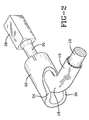
- the mounting end 20 of the mandrel 12 is inserted into a mold cap 22, see FIG. 2.
- the mold cap 22 is a hollow, thick-walled cylinder, but, in accordance with the present invention, a wide mouth groove 24 is provided along the length of the cap 22.
- the mandrel bend 18 and the accompanying hose length 10 project out of the groove 24.
- the mounting end 20 of the mandrel 12 extends out of the bottom 26 of the cap 22 and is secured into the mounting block 28.
- the mounting block 28 is positioned in the curing rack which moved into and out of a vulcanizing unit.
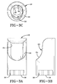
- the cap 22 is better illustrated in FIGS. 3a to 3c.
- the groove 2 4 extends about halfway down the length of the cap 22 and has a width of at least a third of the circumference of the cap 22.
- the groove 24 may have a greater length if needed by the position of the bend 18 in the mandrel 12. Whatever the length of the groove 24 relative to the length of the cap 22, the primary requirement is that no part of the bend 18, and the hose length 10, rest on any lip portion 30 of the groove 24.
- the width of the groove 24 is also dependant upon the size of the mandrel 12 and hose length 10 to be inserted into the cap 22. Similar to the length, the width of the groove 24 must be sufficient to prevent any contact between the hose length 10 and the cap 22.
- the entire lip 30 of the groove 24 is also formed at a sloping angle to form a smooth continuous lip 30 around the entire groove 24.
- the inside portion of the cap 24 located adjacent the lowermost part of the groove, and extending to the base 26 may also be provided with an indentation 32 to assit in any controlling any flow of the hose length 10 during curing.
- the indentation 32 is smoothly sloped.
- the end of the hose length 10 may abut against the base ring 34. If the operator is loading a mandrel 12 already mounted in the cap 22 and the block 28, when he feels the end of the hose length 10 hit the base ring 34, he knows that the hose length 10 is fully inserted onto the mandrel 12.
- the base ring 34 is also provided with a number of lube venting slots 36. Any number of such slots 36 may be located at any position about the base ring 34.
- the illustrated cap 22 has a set of equally spaced four slots 36. Lubrication from the hose length 10 and mandrel 12 may vent out these slots 36 prior to and during curing of the hose length 10.
Landscapes
- Engineering & Computer Science (AREA)
- Mechanical Engineering (AREA)
- Shaping Of Tube Ends By Bending Or Straightening (AREA)
- Heating, Cooling, Or Curing Plastics Or The Like In General (AREA)
Applications Claiming Priority (2)
| Application Number | Priority Date | Filing Date | Title |
|---|---|---|---|
| US992184 | 2001-11-16 | ||
| US09/992,184 US6682335B2 (en) | 2001-11-16 | 2001-11-16 | Hose molding device |
Publications (2)
| Publication Number | Publication Date |
|---|---|
| EP1314537A2 true EP1314537A2 (fr) | 2003-05-28 |
| EP1314537A3 EP1314537A3 (fr) | 2004-11-17 |
Family
ID=25538016
Family Applications (1)
| Application Number | Title | Priority Date | Filing Date |
|---|---|---|---|
| EP02025034A Withdrawn EP1314537A3 (fr) | 2001-11-16 | 2002-11-11 | Dispositif pour mettre en forme un tuyau |
Country Status (7)
| Country | Link |
|---|---|
| US (1) | US6682335B2 (fr) |
| EP (1) | EP1314537A3 (fr) |
| JP (1) | JP2003145549A (fr) |
| CN (1) | CN1203985C (fr) |
| BR (1) | BR0204594A (fr) |
| CA (1) | CA2407856A1 (fr) |
| MX (1) | MXPA02010817A (fr) |
Families Citing this family (6)
| Publication number | Priority date | Publication date | Assignee | Title |
|---|---|---|---|---|
| EP2303411A4 (fr) * | 2008-06-20 | 2013-12-18 | Elkhart Brass Mfg Co | Dispositif de lutte contre l'incendie comprenant une voie à eau |
| WO2015061362A1 (fr) | 2013-10-21 | 2015-04-30 | The Regents Of The University Of California | Enrichissement et détection d'acides nucléiques présentant une très haute sensibilité |
| JP7002364B2 (ja) * | 2018-03-01 | 2022-01-20 | 三桜工業株式会社 | 曲げ成形型 |
| US11387639B2 (en) | 2018-07-11 | 2022-07-12 | Hubbell Incorporated | Electrical box cable connector |
| KR102125514B1 (ko) * | 2018-10-23 | 2020-06-24 | 주식회사 화승알앤에이 | 호스 성형 장치 |
| CN111497198A (zh) * | 2020-04-23 | 2020-08-07 | 厦门蓬欣橡胶制品工业有限公司 | 一种橡胶弯管的生产工艺 |
Family Cites Families (12)
| Publication number | Priority date | Publication date | Assignee | Title |
|---|---|---|---|---|
| DE2422557B2 (de) * | 1974-05-09 | 1977-08-25 | Continental Gummi-Werke Ag, 3000 Hannover | Verfahren und vorrichtung zum herstellen von schlauchkruemmern |
| US3966387A (en) | 1975-06-05 | 1976-06-29 | The B. F. Goodrich Company | Apparatus for vulcanizing hose |
| US4015918A (en) | 1975-06-25 | 1977-04-05 | The Gates Rubber Company | Hose molding device |
| US4131409A (en) | 1977-08-25 | 1978-12-26 | The B. F. Goodrich Company | Apparatus for vulcanizing hose |
| AU6373880A (en) * | 1979-11-09 | 1981-05-14 | Ashland Food Technology Holdings S.A. | Sausage making |
| US4298330A (en) | 1981-08-06 | 1981-11-03 | Dayco Corporation | Curved mandrel for curing polymeric hose and method |
| FR2520664A1 (fr) * | 1982-01-29 | 1983-08-05 | Caoutchouc Manuf Plastique | Procede de fabrication de tuyaux souples de raccordement |
| CA2077400A1 (fr) | 1991-10-08 | 1993-04-09 | Mikhail Leyderman | Mandrin et methode de fabrication d'un article tubulaire rigide |
| US5445360A (en) | 1993-10-12 | 1995-08-29 | Cadillac Rubber & Plastics, Inc. | Thermosetting elastomeric hose having an internal socket formed therein |
| US5565251A (en) * | 1994-10-21 | 1996-10-15 | Btr Antivibration Systems, Inc. | Stabilizer bar bushing with ultra high molecular weight polyethylene lining method of manufacture |
| JP3676871B2 (ja) * | 1995-12-08 | 2005-07-27 | 三恵技研工業株式会社 | 中空二重管の曲げ加工装置 |
| US5800616A (en) * | 1997-12-15 | 1998-09-01 | Sony Corporation | Vertical LPCVD furnace with reversible manifold collar and method of retrofitting same |
-
2001
- 2001-11-16 US US09/992,184 patent/US6682335B2/en not_active Expired - Fee Related
-
2002
- 2002-10-10 CA CA002407856A patent/CA2407856A1/fr not_active Abandoned
- 2002-11-04 MX MXPA02010817A patent/MXPA02010817A/es active IP Right Grant
- 2002-11-05 JP JP2002321026A patent/JP2003145549A/ja not_active Withdrawn
- 2002-11-07 BR BR0204594-0A patent/BR0204594A/pt not_active IP Right Cessation
- 2002-11-11 EP EP02025034A patent/EP1314537A3/fr not_active Withdrawn
- 2002-11-15 CN CN02152219.7A patent/CN1203985C/zh not_active Expired - Fee Related
Also Published As
| Publication number | Publication date |
|---|---|
| US20030096033A1 (en) | 2003-05-22 |
| CN1420015A (zh) | 2003-05-28 |
| CA2407856A1 (fr) | 2003-05-16 |
| CN1203985C (zh) | 2005-06-01 |
| US6682335B2 (en) | 2004-01-27 |
| JP2003145549A (ja) | 2003-05-20 |
| BR0204594A (pt) | 2003-07-15 |
| EP1314537A3 (fr) | 2004-11-17 |
| MXPA02010817A (es) | 2003-08-20 |
Similar Documents
| Publication | Publication Date | Title |
|---|---|---|
| US7216676B2 (en) | Apparatus and method for shaping hose | |
| EP2921426B1 (fr) | Pistons avec un joint à lèvre, système de cartouche utilisant ces pistons, et méthode | |
| EP1314537A2 (fr) | Dispositif pour mettre en forme un tuyau | |
| US10181366B2 (en) | Tape dispensing tool | |
| US4928861A (en) | Plastic-canister screw closure | |
| US6884105B2 (en) | Connector with snap collar latching | |
| US3463517A (en) | Hose coupling having clamp positioning means | |
| EP2020847B1 (fr) | Gobelet-trayeur | |
| US5468329A (en) | Universal pin strip and ring for filament winding | |
| US5813703A (en) | Connector for hoses | |
| US20080012303A1 (en) | Compression clamp | |
| US9862016B2 (en) | Mandrel | |
| US4155966A (en) | Method of making a catheter | |
| US6338397B1 (en) | Device and procedure for the automatic fixing of a lining wear indicator bend | |
| AU603320B2 (en) | Reel tape fixing device and reel | |
| JP6677635B2 (ja) | 車両に自動で再給油する方法およびデバイス | |
| US5694800A (en) | Perfected counterdie for pipe bending machines | |
| JP4868957B2 (ja) | 樹脂チューブ及び樹脂チューブへの継手部材の接続方法 | |
| JP2503725Y2 (ja) | 中通し釣竿 | |
| JP2987826B2 (ja) | 棒状化粧料繰り出し容器の受皿体 | |
| JP2000225652A5 (fr) | ||
| JPH11198954A (ja) | ディスペンサー | |
| US6056023A (en) | Method for making a tubing having lubricant | |
| KR200246220Y1 (ko) | 스텐트제거장치용후크 | |
| JPH09229245A (ja) | 螺旋管の製造方法 |
Legal Events
| Date | Code | Title | Description |
|---|---|---|---|
| PUAI | Public reference made under article 153(3) epc to a published international application that has entered the european phase |
Free format text: ORIGINAL CODE: 0009012 |
|
| AK | Designated contracting states |
Designated state(s): AT BE BG CH CY CZ DE DK EE ES FI FR GB GR IE IT LI LU MC NL PT SE SK TR |
|
| AX | Request for extension of the european patent |
Extension state: AL LT LV MK RO SI |
|
| PUAL | Search report despatched |
Free format text: ORIGINAL CODE: 0009013 |
|
| AK | Designated contracting states |
Kind code of ref document: A3 Designated state(s): AT BE BG CH CY CZ DE DK EE ES FI FR GB GR IE IT LI LU MC NL PT SE SK TR |
|
| AX | Request for extension of the european patent |
Extension state: AL LT LV MK RO SI |
|
| RIC1 | Information provided on ipc code assigned before grant |
Ipc: 7B 29L 23:00 Z Ipc: 7B 29K 21:00 Z Ipc: 7B 29C 53/82 B Ipc: 7B 29C 53/08 A |
|
| 17P | Request for examination filed |
Effective date: 20050517 |
|
| AKX | Designation fees paid |
Designated state(s): DE FR GB IT |
|
| GRAP | Despatch of communication of intention to grant a patent |
Free format text: ORIGINAL CODE: EPIDOSNIGR1 |
|
| RIC1 | Information provided on ipc code assigned before grant |
Ipc: B29L 23/00 20060101ALN20060403BHEP Ipc: B29K 21/00 20060101ALN20060403BHEP Ipc: B29C 53/82 20060101ALI20060403BHEP Ipc: B29C 53/08 20060101AFI20060403BHEP |
|
| STAA | Information on the status of an ep patent application or granted ep patent |
Free format text: STATUS: THE APPLICATION IS DEEMED TO BE WITHDRAWN |
|
| 18D | Application deemed to be withdrawn |
Effective date: 20060825 |