EP1314540A1 - Verfahren zur herstellung gefärbter formgegenstände aus härtbarem harz, gefärbte formgegenstände aus härtbarem harz, und vorrichtung zur formgebung - Google Patents
Verfahren zur herstellung gefärbter formgegenstände aus härtbarem harz, gefärbte formgegenstände aus härtbarem harz, und vorrichtung zur formgebung Download PDFInfo
- Publication number
- EP1314540A1 EP1314540A1 EP01954339A EP01954339A EP1314540A1 EP 1314540 A1 EP1314540 A1 EP 1314540A1 EP 01954339 A EP01954339 A EP 01954339A EP 01954339 A EP01954339 A EP 01954339A EP 1314540 A1 EP1314540 A1 EP 1314540A1
- Authority
- EP
- European Patent Office
- Prior art keywords
- colored
- curable resin
- region
- colorant
- shaped article
- Prior art date
- Legal status (The legal status is an assumption and is not a legal conclusion. Google has not performed a legal analysis and makes no representation as to the accuracy of the status listed.)
- Granted
Links
Images


Classifications
-
- C—CHEMISTRY; METALLURGY
- C08—ORGANIC MACROMOLECULAR COMPOUNDS; THEIR PREPARATION OR CHEMICAL WORKING-UP; COMPOSITIONS BASED THEREON
- C08J—WORKING-UP; GENERAL PROCESSES OF COMPOUNDING; AFTER-TREATMENT NOT COVERED BY SUBCLASSES C08B, C08C, C08F, C08G or C08H
- C08J7/00—Chemical treatment or coating of shaped articles made of macromolecular substances
- C08J7/12—Chemical modification
- C08J7/16—Chemical modification with polymerisable compounds
- C08J7/18—Chemical modification with polymerisable compounds using wave energy or particle radiation
-
- B—PERFORMING OPERATIONS; TRANSPORTING
- B29—WORKING OF PLASTICS; WORKING OF SUBSTANCES IN A PLASTIC STATE IN GENERAL
- B29C—SHAPING OR JOINING OF PLASTICS; SHAPING OF MATERIAL IN A PLASTIC STATE, NOT OTHERWISE PROVIDED FOR; AFTER-TREATMENT OF THE SHAPED PRODUCTS, e.g. REPAIRING
- B29C64/00—Additive manufacturing, i.e. manufacturing of three-dimensional [3D] objects by additive deposition, additive agglomeration or additive layering, e.g. by 3D printing, stereolithography or selective laser sintering
- B29C64/10—Processes of additive manufacturing
- B29C64/106—Processes of additive manufacturing using only liquids or viscous materials, e.g. depositing a continuous bead of viscous material
- B29C64/124—Processes of additive manufacturing using only liquids or viscous materials, e.g. depositing a continuous bead of viscous material using layers of liquid which are selectively solidified
- B29C64/129—Processes of additive manufacturing using only liquids or viscous materials, e.g. depositing a continuous bead of viscous material using layers of liquid which are selectively solidified characterised by the energy source therefor, e.g. by global irradiation combined with a mask
- B29C64/135—Processes of additive manufacturing using only liquids or viscous materials, e.g. depositing a continuous bead of viscous material using layers of liquid which are selectively solidified characterised by the energy source therefor, e.g. by global irradiation combined with a mask the energy source being concentrated, e.g. scanning lasers or focused light sources
-
- B—PERFORMING OPERATIONS; TRANSPORTING
- B29—WORKING OF PLASTICS; WORKING OF SUBSTANCES IN A PLASTIC STATE IN GENERAL
- B29K—INDEXING SCHEME ASSOCIATED WITH SUBCLASSES B29B, B29C OR B29D, RELATING TO MOULDING MATERIALS OR TO MATERIALS FOR MOULDS, REINFORCEMENTS, FILLERS OR PREFORMED PARTS, e.g. INSERTS
- B29K2995/00—Properties of moulding materials, reinforcements, fillers, preformed parts or moulds
- B29K2995/0037—Other properties
- B29K2995/0072—Roughness, e.g. anti-slip
- B29K2995/0073—Roughness, e.g. anti-slip smooth
-
- Y—GENERAL TAGGING OF NEW TECHNOLOGICAL DEVELOPMENTS; GENERAL TAGGING OF CROSS-SECTIONAL TECHNOLOGIES SPANNING OVER SEVERAL SECTIONS OF THE IPC; TECHNICAL SUBJECTS COVERED BY FORMER USPC CROSS-REFERENCE ART COLLECTIONS [XRACs] AND DIGESTS
- Y10—TECHNICAL SUBJECTS COVERED BY FORMER USPC
- Y10T—TECHNICAL SUBJECTS COVERED BY FORMER US CLASSIFICATION
- Y10T428/00—Stock material or miscellaneous articles
- Y10T428/24—Structurally defined web or sheet [e.g., overall dimension, etc.]
- Y10T428/24802—Discontinuous or differential coating, impregnation or bond [e.g., artwork, printing, retouched photograph, etc.]
- Y10T428/24893—Discontinuous or differential coating, impregnation or bond [e.g., artwork, printing, retouched photograph, etc.] including particulate material
- Y10T428/24901—Discontinuous or differential coating, impregnation or bond [e.g., artwork, printing, retouched photograph, etc.] including particulate material including coloring matter
Definitions
- the present invention relates to a process for producing colored shaped article from curable resin, colored shaped article produced from curable resin, and shaping apparatus.
- Coloration of shaped article produced by a photo-model creation method that is, by lamination and shaping using laser beam irradiation of a photo-curable resin is greatly limited by the color (usually, a semitransparent color) inherent to the resin itself. For this reason, a method has been used by which a colorant was added to the produced shaped article upon completion of a series of lamination and shaping operations.
- a method has been attempted by which a colorant is added on the upper surface of the layers each time the layer is formed by the above-mentioned photo-model creation method, that is, a method for curing a photo-curable resin by laser beam irradiation.
- the thickness h' of coating layers 3 1 ⁇ 3 n formed from a colorant is much less than the thickness h of layers 1 1 ⁇ 1 n formed from the photo-curable resin, but when the shaped article is viewed from the upper surface, the color of the colorant appears as a color of the shaped article.
- the shaped article when the shaped article is viewed from the side surface, since the thickness h' of the coating layers 3 1 ⁇ 3 n is very small, as mentioned above, the color (usually, a semitransparent color) inherent to the resin itself, rather than the color of the colorant, appears as the color of the shaped article.
- the resulting problem is that the reliable coloration effect cannot be obtained and, therefore, the above-described colorant addition method cannot be considered effective.
- Another object of the present invention is to conduct reliably the addition operation and to obtain a reliable coloration effect in coloration of a shaped article composed of a curable resin, without using a large-scale equipment.
- the colored shaped article composed of a curable resin which is the first aspect of the present invention, comprises a plurality of layers formed by lamination and shaping of a curable resin, wherein at least one layer of the plurality of layers has a non-colored region where no colorant was added and a colored region formed by adding a colorant, and the colored region is formed so that the color of the colorant can be recognized from all directions of the completed colored shaped article.
- a photo-curable resin is used as the curable resin.
- suitable colorants include compositions prepared by a non-volatile ink using a pigment for ceramics, a colorless finely powdered dye which is colored under UV irradiation, or an ink using a pigment or dye as the raw material with a liquid-phase, curable resin, compositions prepared by mixing a pigment or dye with a liquid-phase solvent other than a curable resin, such compositions having good affinity with the curable resin, compositions prepared by mixing colored fibers or color beads with a liquid-phase, curable resin, and compositions prepared by mixing colored fibers or color beads with a liquid-phase solvent other than a curable resin, such compositions having good affinity with the curable resin.
- a process for producing colored shaped article from curable resin in accordance with the second aspect of the present invention relates to a colored shaped article comprising a plurality of layers formed by lamination and shaping of a curable resin, wherein at least one layer of the plurality of layers has a non-colored region where no colorant was added and a colored region formed by adding a colorant, this process comprising a step of forming the colored region in the liquid-phase, curable resin so that the color of the colorant can be recognized from all directions of the completed colored shaped article and then curing the curable resin and forming a colored region, and a step of curing the curable resin in a liquid-phase state and forming the non-colored region.
- a colored shaped article comprising a plurality of layers formed by lamination and shaping of a curable resin, wherein at least one layer of the plurality of layers has a colored region formed by adding a colorant, this process comprising the steps of forming an external wall by curing a region of prescribed width along the contour line of the colored region, adding a colorant to the region in a liquid-phase state inside the external wall, and curing said colored region.
- a step of forming partition walls by curing the partition zones of prescribed thickness inside the region which is to be colored is implemented prior to the step of adding the colorant. Furthermore, the above-mentioned colored region is formed by adding the prescribed amounts of the colorant at the prescribed distance intervals by using an addition mechanism displaced by feedback-corrected pulse signals.
- the step of adding the colorant comprises a step of removing the liquid-phase, curable resin present in the region which is to be colored and a step of adding the colorant into the region after the removal of the curable resin.
- the addition of colorants of a plurality of colors into the above-mentioned region which is to be colored is conducted by adding the colorants in a sequence starting from the colorant with a color of the highest priority based on the predetermined order of priority. This is conducted to prevent the reduction in size of the colored region caused by multicolor addition and to facilitate recognition of each color.
- a shaping apparatus forms a desired shaped article by lamination and shaping of a liquid-phase, curable resin, this apparatus comprising an addition mechanism that can be displaced in at least the horizontal direction to add a liquid-phase or powdered colorant to the liquid-phase, curable resin.
- a needle mechanism comprising a first colorant supply hole extending, for example, in the axial direction thereof and a second colorant hole perpendicular to the axial direction is employed as the addition mechanism.
- a needle mechanism has a strength and shape allowing for insertion into the liquid-phase, curable resin and three-dimensional displacement in the curable resin.
- an apparatus for the implementation of coloration and shaping will be described below.
- an apparatus with a structure in which a dispenser is supported on a positioning/moving mechanism so that it can be two-dimensionally displaced, such as an XY plotter, or an apparatus with a structure in which a dispenser is supported on a positioning/moving mechanism so that it can be three-dimensionally displaced, such as a robot arm can be used as the above-mentioned apparatus.
- apparatuses with a structure in which a multi-nozzle head (contains no needle-like parts) such as a head of a typical ink-jet printer is supported on an XY plotter or robot arm can be also used as the above-mentioned apparatus.
- the control of various parts of the apparatus is conducted, for example, based on a standard XY table, and when a robot arm is used instead of the XY plotter, the control of various parts of the apparatus is conducted, for example, based on a standard XYZ table.
- the above-mentioned apparatus is not limited to the apparatuses having the configuration described above.
- FIG. 2 is a cross-sectional view illustrating an example of the colored shaped article composed of photo-curable resins relating to an embodiment of the present invention.
- the colored shaped article has a structure obtained by lamination and shaping of a photo-curable resin.
- the shape of the entire shaped article is not limited to any specific shape, and a variety of shapes such as rectangular (square), round, elliptical, and the like can be assumed for a shape viewed from above or below thereof.
- the uppermost layer 5 1 and a lowermost layer 5 n are the layers (usual layers) composed of a non-colored photo-curable resin, and a plurality of layers laminated between the uppermost layer 5 1 and lowermost layer 5 n are the layers (colored layers) 5 2 through 5 n-1 composed of the photo-curable resin colored in various colors.
- Both usual layers 5 1 , 5 n are provided to prevent the decrease in strength of the colored shaped article, which is the cured product, and to protect the coating film comprising a colorant (namely, various color inks, for example volatile inks using a pigment for ceramics).
- the usual layers 5 1 , 5 n are formed only by a curing process (the process in which a non-cured photo-curable resin, that is, a liquid-phase photo-curable resin is cured by illuminating with a laser light) and have the respective prescribed thickness (N layer fraction).
- FIG. 3 is a perspective view illustrating a colored layer used as a colored layer 5 2 positioned in the uppermost portion and a colored layer 5 n-1 positioned in the lowermost portion, of the colored layers 5 2 ⁇ 5 n-1 shown in FIG. 2.
- Those colored layers 5 2 , 5 n-1 are formed so that the colors coated from the upper and lower surfaces of the colored shaped article can be recognized and they comprise a non-colored region A called an outer frame (external wall) and a colored region B formed in the so-called pool region surrounded by the external wall.
- the non-colored region A is formed only by the above-described curing process, similarly to the usual layers (5 1 , 5 n ).
- the colored region B is formed by implementing a process (coloring process) in which the non-cured state (that is, a liquid-phase state) is maintained, without irradiation with the laser beam, during curing of the non-colored region A and a colorant is added to the region in the non-cured state, and then by implementing a curing process similar to the above-described process on this region.
- Curing after coloration of the region in the non-cured state is implemented as processing designed to prevent a negative effect on the formation of the next layer on the aforesaid layer.
- coloration for example, with a color ink, of the region in the non-cured state which becomes the colored region B is conducted, for example, by dropping the color ink onto the region in the non-cured state from a nozzle 7 of a dispenser (not shown in the figure) which is an addition mechanism attached to the front end of a two-axis (XY) robot arm (not shown in the figure).
- a dispenser not shown in the figure
- XY two-axis
- FIG. 4 is a perspective view illustrating the colored layers used as all remaining layers (that is, colored layers 5 3 through 5 n-2 ) sandwiched between the colored layers 5 2 , 5 n-1 of the colored layers 5 2 ⁇ 5 n-1 shown in FIG. 2.
- the colored layers 5 3 through 5 n-2 are employed for the applied colors to be visible from the side surface of the colored shaped article, each of them having an outer-contour non-colored region C called an external wall, a colored region D formed in a region called a groove of a prescribed width that was formed over the entire perimeter along the inner side of the external wall, and an inner-contour non-colored region E on in the inner side of the groove.
- the outer-contour and inner-contour non-colored regions (C, E) are both formed by the curing process similar to that used to form the above-described usual layers (5 1 , 5 n ).
- the colored region D similarly to the colored layers (5 2 , 5 n-1 ) shown in FIG. 3 is formed by maintaining the non-cured state, without irradiation with the laser light, during curing of the outer-contour and inner-contour non-colored regions (C, E) and implementing a coloring process on the region in the non-cured state, and then implementing the curing process (processing creating no obstacles for the formation of the next layer) similar to the above-described process on this region.
- coloration for example, with a color ink, of the region in the non-cured state which becomes the colored region D is conducted by dropping the color ink onto the region in the non-cured state from a nozzle 7 of a dispenser (not shown in the figure) similar to the above-described dispenser.
- the colored shaped article of the above-described configuration can be fabricated by the following process.
- a non-colored photo-curable resin in a non-cured state is irradiated with a laser beam.
- the photo-curable resin is cured and a usual layer with a thickness of N layer fraction is formed as a lowermost layer 5 n .
- a liquid-phase photo-curable resin is coated to the prescribed thickness on the upper surface of the lowermost layer 5 n , only in the region corresponding to the external wall, where the colored layer 5 n-1 shown in FIG. 2 is to be formed, and cured by irradiation with a laser beam, thereby forming a non-colored region A.
- the liquid-phase, photo-curable resin coated on the upper surface of lowermost layer 5 n is separated into the cured non-colored layer A and a pool which is in a non-cured state (liquid-phase state), that is, a region (the above-described colored region B) which is cured after coloration by coating with a color ink.
- This pool is set to have the size (dimensions), and shape such as to produce no effect on the lamination and shaping of the colored shaped article.
- a color ink is dropped as a colorant from the nozzle 7 of the above-mentioned dispenser (not shown in the figure). It is preferred that the color ink used has a very good affinity with the liquid-phase photo-curable resin.
- inks of four colors, red (R), blue (B), yellow (Y), and black (B), are used as the color ink.
- the color ink When the color ink is dropped onto the pool, because of the above-mentioned affinity it diffuses into the photo-curable resin in a non-cured state. As a result, the color ink is added to the entire pool. Once the color ink has been added to the photo-curable resin (that is, the pool) in a non-cured state, the pool is irradiated with a laser beam and the region that becomes the colored region B is cured to the same hardness as the aforesaid non-colored region A. As a result, a block-like coating film having a constant thickness is produced from the surface-like coating film formed by the color ink that is applied on the pool.
- Irradiation with a laser beam of the same energy as that used for curing of the non-colored region A is sometimes insufficient to form the colored region B by curing the above-mentioned region (pool) of the photo-curable resin, which is in a liquid-phase state and has a color ink added thereto, to the same hardness as that of the non-cured region A.
- a special curing method for example, a method of setting a long exposure time during laser beam irradiation or a method of multiple exposure during laser beam irradiation as means for increasing the light energy projected on the region in a liquid-phase state (that is, the region which is to become the colored region B).
- Forming the colored region B by curing the region in a liquid-phase state which has a color ink added thereto makes it possible to form, without obstacles, the next layer (that is, colored layer 5 n-2 ) on the upper surface of colored layer 5 n-1
- a photo-curable resin is added to the prescribed thickness onto the upper surface of colored layer 5 n-1 , and the region corresponding to the external wall and inner contour, where the colored layer 5 n-2 shown in FIG. 2 is to be formed, is cured by irradiation with a laser beam to obtain an outer-contour non-colored region C and an inner-contour non-colored region E.
- the photo-curable resin coated on the upper surface of colored layer 5 n-1 is separated into the cured non-colored regions C, E and a groove in a non-cured state, that is, a region which is to become the above-described colored region D.
- the groove similarly to the above-described pool, is set to have the size (dimensions), and shape such as to produce no effect on the lamination and shaping of the colored shaped article.
- the groove is irradiated with a laser beam and the region that is to become the colored region D is cured to the same hardness as that of the non-colored regions C, E.
- a block-like coating film with a constant thickness is produced from the surface-like coating film formed by the color ink coated on the groove.
- a colored layer 5 2 having the same configuration as the above-described colored layer 5 n-1 is formed on the upper surface of colored layer 5 3 and then a non-colored layer 5 1 having the same configuration as the non-colored layer 5 n is formed on the upper surface of colored layer 5 2 , thereby forming the colored shaped article.
- a controller controlling the units of the shaping apparatus contains shaping data used when the usual layers (5 1 , 5 n ) are formed, shaping data used when the colored layers (5 2 , 5 n-1 ) are formed, and shaping data used when the colored layers (5 3 through 5 n-2 ) are formed.
- the controller (not shown in the figures) provides for lamination and shaping of the above-mentioned colored shaped article by appropriately using a variety of the shaping data.
- a colorant was added to the layers (5 2 through 5 n-1 ). which are to be colored, in the process of lamination and shaping of the colored shaped article. Therefore, the process for adding the colorant after the completion of the series of shaping operations was unnecessary.
- the automation of colorant addition operation can be conducted together with the automation of shaping operation carried out with the shaping apparatus. Therefore, the addition operation can be conducted while the shaping operation is being conducted, and not only single-color, but also multicolor addition can be conducted.
- FIG. 5 illustrates an example of a method for forming a layer (colored layer) consisting of a colored photo-curable resin described with reference to FIG. 3.
- the external wall front surface 9 of the above-described colored layers (5 2 , 5 n-1 ) is formed based on the data (front surface data) representing the external wall front surface 9 determined by slicing the STL data. Furthermore, the external wall inner surface 11 of the colored layers (5 2 , 5 n-1 ) is formed based on the data (inner surface data) determined by offsetting the above-mentioned front surface data inward through a certain distance.
- the external wall inner surface 11 is equivalent to the outer periphery of the pool, that is, the region which is to become the colored region B.
- a rectangular line 13 indicating the trajectory of the position of color ink that is, the colorant, dropping on the region which is to become the colored region B is determined based on the data (data for ink dropping) found by offsetting the inner surface data inward through a certain distance.
- the external wall front surface 9 is formed based on the front surface data
- the outer periphery of the groove that is, the region which is to become the colored region D
- the inner periphery of the region which is to become the colored region D is determined based on the data found by offsetting the inner surface data inward through a certain distance exceeding the rectangular line 13 for ink dropping.
- the rectangular line 13 representing the trajectory of the color ink dropping position is preferably set in a position at a distance of about 1.0 to 5.0 mm from the external wall inner surface 11, though the diffusion surface area may vary depending on the shape of the formed colored shaped article and the relationship between the surface tension of the colored ink which is drop-wise added and the photo-curable resin in a liquid-phase state.
- composition prepared by dissolving a powder consisting of colorless particles of a very small diameter which are characterized by the ability to be colored under UV irradiation in a photo-curable resin was used as a dye (color ink) for coloration employed for the test. Since the particles were colorless, they produced no adverse effect on the UV transmissivity in the photo-curable resin even after they were drop-wise added to the photo-curable resin in a liquid-phase state. Accordingly, they did not hinder the curing process.
- FIG. 6 illustrates a modification of the formation method described with reference to FIG. 5
- a wall 15 is provided on the outer periphery of this region. Furthermore, partition walls 17 are also provided to prevent mixing of color inks of different colors when multicolor addition is conducted on a portion of this region.
- the appropriate thickness of walls 15, 17 is about 0.5-5.0 mm, though it depends on the shape of the region.
- the wall thickness may be decreased to facilitate the observation of color provided to a photo-curable resin in a liquid-phase state. However, if the wall thickness is less than 0.5 to 5.0 mm, there is a possibility that the color ink drop wise added to the region will ooze out of the region.
- An STL data format is employed in the controller (not shown in the figures) of the shaping apparatus in order to implement the formation method shown in FIG. 6.
- the STL format by itself has no color information. For this reason, files for each color are created in the controller and identification of various colors is executed.
- FIG. 7 illustrates an example of a method for coloring a layer consisting of a curable resin, while suppressing the build-up of the colorant (color ink).
- color ink dropped onto a photo-curable resin in a liquid-phase state diffuses over the resin liquid surface. Therefore, data (coloration data) used to cause the adhesion of color ink to the photo-curable ink should not be as specific as data (shaping data) used when the photo-curable resins in a liquid-phase state are laminated and shaped. If the coloration data are too specific, the amount of added color ink is increased accordingly and the added color ink builds up in the pool region in the colored layers (5 2 , 5 n-1 ) shown in FIG. 3 or in the groove region in the colored layers (5 3 ⁇ 5 n-2 ) shown in FIG. 4, thereby hindering the above-mentioned lamination and shaping.
- the colored region F shows shaping data relating to shaping of a colored layer having a disk-like shape.
- the concentric circular arc G positioned on the inner periphery thereof represents the original coloration data produced by offsetting the shaping data through a certain distance, that is, the trajectory of nozzle 7 of the above-mentioned dispenser (not shown in the figure).
- the so called thinning of coloration data is conducted according to the below-described procedure by using this circular arc G.
- a plurality of equidistant apexes G 1 through G n are determined on the coloration data (circular arc G). More specifically, the apexes G 1 through G n are determined by finding the coordinates indicating the apexes G 1 through G n . Then, as shown in FIG. 7(c), for example, an apex G 1 selected from the apexes G 1 ⁇ G n is determined as an initial point P 1 of coloration data and the apex G 3 separated from this initial point P 1 by a distance of no less than the prescribed distance t is assumed to be a second point P 2 of coloration data, following the initial point P 1 .
- the third point P 3 of coloration data, ..., and n-th point of coloration data, that is, the final point P n is found.
- the final point P n should be selected so as to be separated from the initial point P 1 by a distance of no less than the aforesaid distance t.
- the colorants are added in respective prescribed amounts in the points P 1 , P 2 , P 3 .... P n that were thus selected.
- FIG. 8 illustrates another example of the coloration method described with reference to FIG. 7.
- the color ink was dropped from the nozzle 7 of a dispenser (not shown in the figures) located at a height of 5 to 10 mm above the surface of the photo-curable resin in a liquid-phase state.
- a dispenser not shown in the figures
- modifying the structure of nozzle 7 so as to obtain a sufficient strength and a shape allowing for insertion into the photo-curable resin in a liquid-phase state and removal therefrom makes it possible to conduct coloration by inserting the nozzle 7 into the photo-curable resin in a liquid-phase state, as shown in FIG. 8(b). Inserting the nozzle 7 into the photo-curable resin in a liquid-phase state allows for coloration in a state in which the color ink was greatly diffused.
- nozzle 7 Furthermore, spattering of ink is also prevented and accurate control of the vertical position of nozzle 7 becomes unnecessary. Moreover, if a nozzle with a plurality of transverse holes 7a ⁇ 7n in a side surface, which is shown in FIG. 8(c), is used as the nozzle 7, the coloration can be conducted in a state in which the color ink was diffused even more significantly.
- the color ink is dropped after being heated inside the dispenser (not shown in the figures) or in the nozzle 7. If a color ink is at a low temperature, the viscosity thereof is higher. As a result, the diffusion thereof requires certain time. Therefore, the color ink added to the non-cured portions of the photo-curable resin, such as the above-described pool or groove, does not diffuse uniformly and coloration defects are produced. However, if the color ink dropped upon heating, because the viscosity is low, the ink diffuses within a comparatively short time. As a result, the coloration defects are prevented.
- nozzle 7 can be modified to provide for more uniform diffusion of color ink and more effective elimination of coloration defects.
- a structure may be used in which longitudinal holes opened in the bottom portion of nozzle 7 are provided in addition to transverse holes 7a ⁇ 7n shown in FIG. 8(c).
- FIG. 9 shows still another example of the coloration method illustrated by FIG. 7 and compares the results obtained by the coloration methods illustrated by FIG. 7 and FIG. 8.
- FIG. 9(a) With the coloration methods illustrated by FIG. 7 and FIG. 8, first, as shown in FIG. 9(a) only the external wall was cured and the region corresponding to the pool (or groove) was left in a liquid-phase state. Then, as shown in FIG. 9(b), a color ink was dropped from the nozzle 7 of a dispenser (not shown in the figures) into the pool (or groove) region which was in a non-cured state. As a result, as shown in FIG. 9(c), a build-up in an amount of the dropped color ink appeared in the pool (or groove) region, and shaping of the next layer on the upper surface of the layer shown in the figure was impossible at a lamination pitch with a thickness of no more than the build-up. In other words, a small lamination pitch could not be set.
- a method of applying air pressure to the dropping site of color ink is still another means for preventing the build-up of color ink dropped on the non-cured photo-curable resin. Furthermore, a method of applying vibrations to the dropping site of color ink is a means for preventing the build-up of the color ink and also enhancing the diffusion thereof.
- compositions prepared by admixing pigments, dyes, or inks prepared by using them as raw material to the photo-curable resin in a liquid-phase state and compositions prepared by dissolving pigments or dyes in solvents other than photo-curable resins in a liquid-phase state can be used as the above-mentioned color ink.
- the compositions prepared by dissolving pigments or dyes in solvents other than photo-curable resins in a liquid-phase state they should have affinity with photo-curable resins, in other words, they should not hinder the curing of photo-curable resins.
- compositions using fibers or color beads instead of pigments and dyes can be also used as the color ink.
- a photo-curable resin layer is cured and a thin film is formed by irradiating the photo-curable resin in a liquid-phase state with a laser beam. Then a color ink is added on the thin film according to the offset data (data obtained by offsetting the contour shape data inward by about 0.5 to 5.0 mm) of shaping data (data representing the contour shape of colored shaped article) of colored shaped article.
- the offset data data obtained by offsetting the contour shape data inward by about 0.5 to 5.0 mm
- shaping data data representing the contour shape of colored shaped article
- the addition of color ink is repeated multiple times and the build-up of the added color ink is formed within a range in which the prescribed lamination pitch is not reached.
- a photo-curable resin in a liquid-phase state is added onto the surface thereof, this resin being required for forming the next layer. Then, the photo-curable resin in a liquid-phase state is irradiated with a laser beam according to the shape data of the next layer and the photo-curable resin is cured so as to obtain the prescribed shape.
- the desired colored shaped article is formed by repeating the above-described process the required number of times.
- the build-up with a prescribed thickness is formed from a color ink by multiple addition of the color ink.
- a color sheet having a thickness that does not exceed the lamination pitch may be cut to the desired shape and then glued to the liquid-phase, photo-curable resin.
- a color sheet having a thickness that does not exceed the lamination pitch may be cut to the desired shape after gluing to the liquid-phase photo-curable resin.
- a color sheets having a thickness exceeding the lamination pitch is preferably not used because it hinders lamination and shaping.
- a method of adding a viscous color ink for example, a color resin only one time can be used instead of the method of multiple addition of color ink.
- the addition of color resin is conducted while the thickness of coating film formed by adding the color resin is being controlled so that it approaches as close as possible to the thickness of lamination pitch.
- a method in which a color ink is dropped onto a liquid-phase, photo-curable resin after recoating and the liquid-phase photo-curable resin is cured faster than the dropped color ink diffuses into the photo-curable resin can be used as a shaping method that does not require the formation of the above-mentioned external wall.
- the outflow of color ink into a region which is not to be colored is prevented by conducting dropping of color ink and curing of the liquid-phase photo-curable resin practically at the same time.
- the desired colored shaped article can be formed by adding (printing) a color ink to the resin after recoating (that is, a liquid-phase photo-curable resin), for example, by using a mechanism similar to that of ink-jet printers and then repeating the process of curing the resin for each layer.
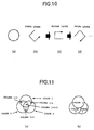
- FIG. 10 illustrates an example of a method by which coloration in the layers of a colored shaped article consisting of a photo-curable resin in a state in which the coloration region is averaged over the entire body, based on the method illustrated by FIG. 7.
- coloration was conducted by using thinning coloration data in which the initial points were randomly made different for all of the layers, so that in the apexes P 1 ⁇ P n (FIG. 10(a)) located on a circular arc G obtained by the method illustrated by FIG. 7, the thinning coloration data having the apex P 1 as the initial point were used for the first layer (FIG. 10(b)), the thinning coloration data having the apex P 3 as the initial point were used for the second layer (FIG. 10(c)), and the thinning coloration data having the apex P 2 as the initial point were used for the third layer (FIG. 10(d)).
- the colorant (color ink) addition regions based on those coloration data are shifted in each of the layers and, as a result, the colorant addition regions are averaged and dispersed, as viewed over the entire colored shaped article.
- FIG.11 illustrates an example of a method for multicolor coloration of a layer consisting of a curable resin, without decreasing the size of coloration region.
- FIG. 11 (a) a region in which coloration is conducted with a color other than the color relating to coloration data will expand, as shown in FIG. 11 (a).
- the colors of coloration data are color 1, color 2, and color 3, actually, a portion in which the coloration region of color 1 and the coloration region of color 2 overlap, a portion in which the coloration region of color 1 and the coloration region of color 3 overlap, a portion in which the coloration region of color 2 and the coloration region of color 3 overlap, and a portion in which the coloration regions of color 1, color 2, and color 3 overlap expand correspondingly.
- a priority of colors was established during coloration.
- the priority can be freely determined depending on what color of the colored shaped article should be conspicuous, in user's opinion. For example, if among the above-mentioned color 1, color 2, and color 3, color 1 should be the most conspicuous, followed by color 2, then coloration with the above-mentioned color separation is conducted according to the pattern shown in FIG. 11(b). As a result, the reduction of coloration regions in size caused by the multicolor addition can be prevented.
Landscapes
- Chemical & Material Sciences (AREA)
- Physics & Mathematics (AREA)
- Optics & Photonics (AREA)
- Engineering & Computer Science (AREA)
- Materials Engineering (AREA)
- Mechanical Engineering (AREA)
- Manufacturing & Machinery (AREA)
- Health & Medical Sciences (AREA)
- Toxicology (AREA)
- General Chemical & Material Sciences (AREA)
- Chemical Kinetics & Catalysis (AREA)
- Medicinal Chemistry (AREA)
- Polymers & Plastics (AREA)
- Organic Chemistry (AREA)
- Compositions Of Macromolecular Compounds (AREA)
Applications Claiming Priority (3)
| Application Number | Priority Date | Filing Date | Title |
|---|---|---|---|
| JP2000229191A JP4493814B2 (ja) | 2000-07-28 | 2000-07-28 | 硬化性樹脂から成る着色造形物の製造方法および製造装置 |
| JP2000229191 | 2000-07-28 | ||
| PCT/JP2001/006422 WO2002009928A1 (en) | 2000-07-28 | 2001-07-26 | Process for producing colored shaped article from curable resin, colored shaped article produced from curable resin, and shaping apparatus |
Publications (3)
| Publication Number | Publication Date |
|---|---|
| EP1314540A1 true EP1314540A1 (de) | 2003-05-28 |
| EP1314540A4 EP1314540A4 (de) | 2003-05-28 |
| EP1314540B1 EP1314540B1 (de) | 2004-10-13 |
Family
ID=18722354
Family Applications (1)
| Application Number | Title | Priority Date | Filing Date |
|---|---|---|---|
| EP01954339A Expired - Lifetime EP1314540B1 (de) | 2000-07-28 | 2001-07-26 | Verfahren zur herstellung gefärbter formgegenstände aus härtbarem harz, und vorrichtung zur formgebung |
Country Status (8)
| Country | Link |
|---|---|
| US (1) | US7074354B2 (de) |
| EP (1) | EP1314540B1 (de) |
| JP (1) | JP4493814B2 (de) |
| KR (1) | KR100490610B1 (de) |
| CN (1) | CN1241728C (de) |
| DE (1) | DE60106465T2 (de) |
| TW (1) | TW499360B (de) |
| WO (1) | WO2002009928A1 (de) |
Cited By (3)
| Publication number | Priority date | Publication date | Assignee | Title |
|---|---|---|---|---|
| EP2671706A1 (de) * | 2012-06-04 | 2013-12-11 | Ivoclar Vivadent AG | Verfahren zum Aufbau eines Formkörpers |
| EP3220623A1 (de) * | 2016-03-18 | 2017-09-20 | XYZprinting, Inc. | Schneiddruckverfahren für farbiges 3d-modell |
| EP3747632A1 (de) * | 2010-10-27 | 2020-12-09 | Rize Inc. | Verfahren und vorrichtung für die herstellung von dreidimensionalen gegenständen |
Families Citing this family (21)
| Publication number | Priority date | Publication date | Assignee | Title |
|---|---|---|---|---|
| WO2005037529A1 (ja) * | 2003-10-20 | 2005-04-28 | National Institute Of Advanced Industrial Science And Technology | 3次元造形物の作製方法および3次元造形物 |
| JP2007000964A (ja) * | 2005-06-23 | 2007-01-11 | Tohoku Univ | 樹脂製マイクロマシン部品の製造方法 |
| JP2011037183A (ja) * | 2009-08-14 | 2011-02-24 | Olympus Corp | 硬化反応装置及びその硬化方法 |
| US9073259B2 (en) * | 2011-11-29 | 2015-07-07 | Xerox Corporation | Media-based system for forming three-dimensional objects |
| US9740716B2 (en) * | 2013-08-21 | 2017-08-22 | Oracle International Corporation | System and method for dynamically selecting a garbage collection algorithm based on the contents of heap regions |
| TWI548540B (zh) * | 2014-02-27 | 2016-09-11 | 三緯國際立體列印科技股份有限公司 | 立體列印方法 |
| JP6510179B2 (ja) * | 2014-04-16 | 2019-05-08 | 株式会社ミマキエンジニアリング | 3次元プリンタ、及び、3次元造形物製造方法 |
| JP6451234B2 (ja) * | 2014-11-12 | 2019-01-16 | セイコーエプソン株式会社 | 立体物造形装置、立体物造形装置の制御方法、立体物造形装置の制御プログラム |
| WO2017038985A1 (ja) * | 2015-09-04 | 2017-03-09 | Jsr株式会社 | 立体造形物の製造方法及びこれに用いられるノズル移動経路のデータ作成方法、並びに立体造形物の製造装置及びこれに用いられるノズル移動経路のデータ作成プログラム |
| DE102015222758A1 (de) * | 2015-11-18 | 2017-05-18 | BSH Hausgeräte GmbH | Druckeinheit für den Druck von Nahrungsmitteln |
| JP6839509B2 (ja) | 2016-02-29 | 2021-03-10 | 株式会社ミマキエンジニアリング | 三次元造形物製造方法および造形装置 |
| WO2017150196A1 (ja) * | 2016-02-29 | 2017-09-08 | 株式会社ミマキエンジニアリング | 三次元造形物製造方法、三次元造形物および造形装置 |
| TWI659866B (zh) * | 2017-02-17 | 2019-05-21 | 三緯國際立體列印科技股份有限公司 | 立體列印裝置及其列印方法 |
| TWI723156B (zh) * | 2017-04-20 | 2021-04-01 | 三緯國際立體列印科技股份有限公司 | 彩色3d物件的著色輪廓內縮方法 |
| EP3606727A4 (de) * | 2017-07-10 | 2020-11-25 | Hewlett-Packard Development Company, L.P. | Verschachtelte segmente in objektmodellen für die generative fertigung |
| CN107385959A (zh) * | 2017-08-25 | 2017-11-24 | 贵州盛茂白芨开发有限公司 | 一种白芨染料的染色方法 |
| CN109421257A (zh) * | 2017-08-31 | 2019-03-05 | 三纬国际立体列印科技股份有限公司 | 彩色3d物件的着色区域内缩方法 |
| JP2019115984A (ja) * | 2017-12-26 | 2019-07-18 | 株式会社びーふる | 三次元造形物及びこの製造方法 |
| US20230390999A1 (en) * | 2022-06-03 | 2023-12-07 | Sakuu Corporation | Apparatus and method of binder jetting 3d printing |
| CN117087159A (zh) * | 2023-08-01 | 2023-11-21 | 深圳市纵维立方科技有限公司 | 打印控制方法、装置、可读存储介质和光固化三维打印设备 |
| CN117021580A (zh) * | 2023-08-01 | 2023-11-10 | 深圳市纵维立方科技有限公司 | 一种模型切片图像处理方法、装置、计算机设备和可读存储介质 |
Family Cites Families (16)
| Publication number | Priority date | Publication date | Assignee | Title |
|---|---|---|---|---|
| GB2233928B (en) * | 1989-05-23 | 1992-12-23 | Brother Ind Ltd | Apparatus and method for forming three-dimensional article |
| US5121329A (en) * | 1989-10-30 | 1992-06-09 | Stratasys, Inc. | Apparatus and method for creating three-dimensional objects |
| US5096530A (en) * | 1990-06-28 | 1992-03-17 | 3D Systems, Inc. | Resin film recoating method and apparatus |
| US5594652A (en) * | 1991-01-31 | 1997-01-14 | Texas Instruments Incorporated | Method and apparatus for the computer-controlled manufacture of three-dimensional objects from computer data |
| US5278442A (en) * | 1991-07-15 | 1994-01-11 | Prinz Fritz B | Electronic packages and smart structures formed by thermal spray deposition |
| JP3248006B2 (ja) * | 1991-10-02 | 2002-01-21 | バンティコ アクチエンゲゼルシャフト | 三次元物体の製造方法 |
| JP3200912B2 (ja) * | 1992-02-04 | 2001-08-20 | ジェイエスアール株式会社 | 立体モデルの製造方法 |
| JP3155110B2 (ja) * | 1992-02-15 | 2001-04-09 | 松下電工株式会社 | 三次元形状の形成方法 |
| GB9313723D0 (en) * | 1993-07-02 | 1993-08-18 | Zeneca Ltd | Process |
| DK0854783T3 (da) | 1995-09-09 | 2003-02-24 | Vantico Ltd | Fremgangsmåde til fremstilling af polymerlag med selektivt farvede arealer |
| JP3724893B2 (ja) * | 1996-09-25 | 2005-12-07 | ナブテスコ株式会社 | 光学的立体造形用樹脂組成物 |
| JP4415206B2 (ja) * | 1998-07-25 | 2010-02-17 | バンティコ リミテッド | 変色組成物およびそれから作製される着色ポリマー物品 |
| US6165406A (en) * | 1999-05-27 | 2000-12-26 | Nanotek Instruments, Inc. | 3-D color model making apparatus and process |
| JP2001018297A (ja) * | 1999-07-09 | 2001-01-23 | Canon Inc | カラー立体モデル形成方法及び装置 |
| JP2001118297A (ja) | 1999-10-14 | 2001-04-27 | Funai Electric Co Ltd | 記録制御装置および記録制御方法 |
| NL1013460C2 (nl) * | 1999-11-02 | 2001-05-03 | Tno | Werkwijze voor het vervaardigen van een product met lokaal specifieke eigenschappen. |
-
2000
- 2000-07-28 JP JP2000229191A patent/JP4493814B2/ja not_active Expired - Fee Related
-
2001
- 2001-07-26 CN CNB018021344A patent/CN1241728C/zh not_active Expired - Fee Related
- 2001-07-26 US US10/089,327 patent/US7074354B2/en not_active Expired - Lifetime
- 2001-07-26 WO PCT/JP2001/006422 patent/WO2002009928A1/ja not_active Ceased
- 2001-07-26 KR KR10-2002-7003035A patent/KR100490610B1/ko not_active Expired - Fee Related
- 2001-07-26 EP EP01954339A patent/EP1314540B1/de not_active Expired - Lifetime
- 2001-07-26 DE DE60106465T patent/DE60106465T2/de not_active Expired - Lifetime
- 2001-07-27 TW TW090118367A patent/TW499360B/zh active
Cited By (6)
| Publication number | Priority date | Publication date | Assignee | Title |
|---|---|---|---|---|
| EP3747632A1 (de) * | 2010-10-27 | 2020-12-09 | Rize Inc. | Verfahren und vorrichtung für die herstellung von dreidimensionalen gegenständen |
| EP2671706A1 (de) * | 2012-06-04 | 2013-12-11 | Ivoclar Vivadent AG | Verfahren zum Aufbau eines Formkörpers |
| WO2013182547A1 (de) * | 2012-06-04 | 2013-12-12 | Ivoclar Vivadent Ag | Verfahren zum aufbau eines dreidimensionalen formkörpers |
| US9592635B2 (en) | 2012-06-04 | 2017-03-14 | Ivoclar Vivadent Ag | Method for the construction of a shaped body |
| EP3220623A1 (de) * | 2016-03-18 | 2017-09-20 | XYZprinting, Inc. | Schneiddruckverfahren für farbiges 3d-modell |
| US10252464B2 (en) | 2016-03-18 | 2019-04-09 | Xyzprinting, Inc. | Slicing printing method for color 3D model |
Also Published As
| Publication number | Publication date |
|---|---|
| CN1386090A (zh) | 2002-12-18 |
| EP1314540B1 (de) | 2004-10-13 |
| KR20020042668A (ko) | 2002-06-05 |
| TW499360B (en) | 2002-08-21 |
| JP2002036374A (ja) | 2002-02-05 |
| CN1241728C (zh) | 2006-02-15 |
| DE60106465D1 (de) | 2004-11-18 |
| DE60106465T2 (de) | 2005-10-13 |
| JP4493814B2 (ja) | 2010-06-30 |
| KR100490610B1 (ko) | 2005-05-17 |
| EP1314540A4 (de) | 2003-05-28 |
| WO2002009928A1 (en) | 2002-02-07 |
| US20040105967A1 (en) | 2004-06-03 |
| US7074354B2 (en) | 2006-07-11 |
Similar Documents
| Publication | Publication Date | Title |
|---|---|---|
| US7074354B2 (en) | Process for producing colored shaped article from curable resin, colored shaped article produced from curable resin, and shaping apparatus | |
| US20200130255A1 (en) | Method for modeling three-dimensional object | |
| US20210245421A1 (en) | Liquid drop discharge system | |
| US10065376B2 (en) | Three-dimensional object fabrication device, three-dimensional object fabrication method, and three-dimensional object | |
| DE60119576T2 (de) | Tintenstrahldrucker mit drehbarer trommel für strahlungshärtbare tinte | |
| US6394578B1 (en) | Production process of color filter, liquid crystal display device using the color filter produced by the production process, and ink-jet head | |
| US6490968B2 (en) | Method of finishing golf balls employing direct digital-to-surface printing of indicia | |
| EP3466646B1 (de) | Formgebungsvorrichtung und formgebungsverfahren | |
| GB2233928A (en) | Forming an article from computer controlled jet of photosetting resin droplets. | |
| JP2000304988A (ja) | 色分けされた光ファイバリボンおよびそれを製造するためのダイ | |
| KR102709849B1 (ko) | 인쇄 제제 및 방법 | |
| DE69114938T2 (de) | Farbstrahlaufzeichnungskopfherstellungsverfahren. | |
| DE3528064A1 (de) | Fluessigkeitsstrahlaufzeichnungskopf und damit versehenes fluessigkeitsstrahlaufzeichnungsgeraet | |
| JP2006027015A (ja) | 光造形装置、コータ及び光造形方法 | |
| RU1800273C (ru) | Способ струйной многоцветной печати, струйна печатающа головка дл его осуществлени и способ изготовлени такой головки | |
| JP2019014067A (ja) | 産業用インクジェット描画装置 | |
| JP2000108216A (ja) | マイクロレンズアレイの製造方法 | |
| JP2002001828A (ja) | 接着液、着色材料および着色方法 | |
| DE69927211T2 (de) | Zeilendruckkopf für Tintenstrahldrucker | |
| JP2001354877A (ja) | 無機顔料インキ及びその使用方法、並びに無機顔料インキを使用した積層造形方法 | |
| JP2005296418A (ja) | 遊技機用部品及びその製造方法 | |
| JPH11153710A (ja) | カラーフィルタの製造方法と製造装置 | |
| JP2001353787A (ja) | 接着液および三次元造形方法 | |
| EP3103621B1 (de) | Verfahren für erhöhtes drucken | |
| JP2003195024A (ja) | カラーフィルタ製造装置及び製造方法 |
Legal Events
| Date | Code | Title | Description |
|---|---|---|---|
| PUAI | Public reference made under article 153(3) epc to a published international application that has entered the european phase |
Free format text: ORIGINAL CODE: 0009012 |
|
| 17P | Request for examination filed |
Effective date: 20020326 |
|
| A4 | Supplementary search report drawn up and despatched |
Effective date: 20021106 |
|
| AK | Designated contracting states |
Designated state(s): AT BE CH CY DE DK ES FI FR GB GR IE IT LI LU MC NL PT SE TR |
|
| 17Q | First examination report despatched |
Effective date: 20030523 |
|
| GRAP | Despatch of communication of intention to grant a patent |
Free format text: ORIGINAL CODE: EPIDOSNIGR1 |
|
| RTI1 | Title (correction) |
Free format text: PROCESS FOR PRODUCING COLORED SHAPED ARTICLES FROM CURABLE RESIN, AND SHAPING APPARATUS |
|
| RBV | Designated contracting states (corrected) |
Designated state(s): AT BE CH DE FR GB LI |
|
| RBV | Designated contracting states (corrected) |
Designated state(s): DE FR GB |
|
| GRAS | Grant fee paid |
Free format text: ORIGINAL CODE: EPIDOSNIGR3 |
|
| GRAA | (expected) grant |
Free format text: ORIGINAL CODE: 0009210 |
|
| AK | Designated contracting states |
Kind code of ref document: B1 Designated state(s): DE FR GB |
|
| REG | Reference to a national code |
Ref country code: GB Ref legal event code: FG4D |
|
| REG | Reference to a national code |
Ref country code: IE Ref legal event code: FG4D |
|
| REF | Corresponds to: |
Ref document number: 60106465 Country of ref document: DE Date of ref document: 20041118 Kind code of ref document: P |
|
| PLBE | No opposition filed within time limit |
Free format text: ORIGINAL CODE: 0009261 |
|
| STAA | Information on the status of an ep patent application or granted ep patent |
Free format text: STATUS: NO OPPOSITION FILED WITHIN TIME LIMIT |
|
| ET | Fr: translation filed | ||
| 26N | No opposition filed |
Effective date: 20050714 |
|
| REG | Reference to a national code |
Ref country code: GB Ref legal event code: 732E |
|
| REG | Reference to a national code |
Ref country code: FR Ref legal event code: TQ |
|
| PGFP | Annual fee paid to national office [announced via postgrant information from national office to epo] |
Ref country code: FR Payment date: 20060719 Year of fee payment: 6 |
|
| PGFP | Annual fee paid to national office [announced via postgrant information from national office to epo] |
Ref country code: GB Payment date: 20060726 Year of fee payment: 6 |
|
| GBPC | Gb: european patent ceased through non-payment of renewal fee |
Effective date: 20070726 |
|
| PG25 | Lapsed in a contracting state [announced via postgrant information from national office to epo] |
Ref country code: GB Free format text: LAPSE BECAUSE OF NON-PAYMENT OF DUE FEES Effective date: 20070726 |
|
| REG | Reference to a national code |
Ref country code: FR Ref legal event code: ST Effective date: 20080331 |
|
| PG25 | Lapsed in a contracting state [announced via postgrant information from national office to epo] |
Ref country code: FR Free format text: LAPSE BECAUSE OF NON-PAYMENT OF DUE FEES Effective date: 20070731 |
|
| REG | Reference to a national code |
Ref country code: DE Ref legal event code: R082 Ref document number: 60106465 Country of ref document: DE Representative=s name: HOFFMANN, ECKART, DIPL.-ING., DE |
|
| REG | Reference to a national code |
Ref country code: DE Ref legal event code: R081 Ref document number: 60106465 Country of ref document: DE Owner name: NABTESCO CORPORATION, JP Free format text: FORMER OWNERS: NABTESCO CORP., TOKIO/TOKYO, JP; RIKEN, WAKO-SHI, SAITAMA, JP Effective date: 20140527 Ref country code: DE Ref legal event code: R081 Ref document number: 60106465 Country of ref document: DE Owner name: NABTESCO CORPORATION, JP Free format text: FORMER OWNER: NABTESCO CORP., RIKEN, , JP Effective date: 20140527 Ref country code: DE Ref legal event code: R082 Ref document number: 60106465 Country of ref document: DE Representative=s name: HOFFMANN, ECKART, DIPL.-ING., DE Effective date: 20140527 |
|
| REG | Reference to a national code |
Ref country code: DE Ref legal event code: R079 Ref document number: 60106465 Country of ref document: DE Free format text: PREVIOUS MAIN CLASS: B29C0067000000 Ipc: B29C0064106000 |
|
| PGFP | Annual fee paid to national office [announced via postgrant information from national office to epo] |
Ref country code: DE Payment date: 20170724 Year of fee payment: 17 |
|
| REG | Reference to a national code |
Ref country code: DE Ref legal event code: R119 Ref document number: 60106465 Country of ref document: DE |
|
| PG25 | Lapsed in a contracting state [announced via postgrant information from national office to epo] |
Ref country code: DE Free format text: LAPSE BECAUSE OF NON-PAYMENT OF DUE FEES Effective date: 20190201 |