EP1314603B1 - Fermeture à cames à faible perméabilité pour soupape d'évacuation de vapeurs pour réservoir de carburant en matière plastique - Google Patents
Fermeture à cames à faible perméabilité pour soupape d'évacuation de vapeurs pour réservoir de carburant en matière plastique Download PDFInfo
- Publication number
- EP1314603B1 EP1314603B1 EP02024861A EP02024861A EP1314603B1 EP 1314603 B1 EP1314603 B1 EP 1314603B1 EP 02024861 A EP02024861 A EP 02024861A EP 02024861 A EP02024861 A EP 02024861A EP 1314603 B1 EP1314603 B1 EP 1314603B1
- Authority
- EP
- European Patent Office
- Prior art keywords
- spring
- valve
- annular
- access opening
- tank
- Prior art date
- Legal status (The legal status is an assumption and is not a legal conclusion. Google has not performed a legal analysis and makes no representation as to the accuracy of the status listed.)
- Expired - Lifetime
Links
Images


Classifications
-
- B—PERFORMING OPERATIONS; TRANSPORTING
- B60—VEHICLES IN GENERAL
- B60K—ARRANGEMENT OR MOUNTING OF PROPULSION UNITS OR OF TRANSMISSIONS IN VEHICLES; ARRANGEMENT OR MOUNTING OF PLURAL DIVERSE PRIME-MOVERS IN VEHICLES; AUXILIARY DRIVES FOR VEHICLES; INSTRUMENTATION OR DASHBOARDS FOR VEHICLES; ARRANGEMENTS IN CONNECTION WITH COOLING, AIR INTAKE, GAS EXHAUST OR FUEL SUPPLY OF PROPULSION UNITS IN VEHICLES
- B60K15/00—Arrangement in connection with fuel supply of combustion engines or other fuel consuming energy converters, e.g. fuel cells; Mounting or construction of fuel tanks
- B60K15/03—Fuel tanks
- B60K15/035—Fuel tanks characterised by venting means
-
- B—PERFORMING OPERATIONS; TRANSPORTING
- B60—VEHICLES IN GENERAL
- B60K—ARRANGEMENT OR MOUNTING OF PROPULSION UNITS OR OF TRANSMISSIONS IN VEHICLES; ARRANGEMENT OR MOUNTING OF PLURAL DIVERSE PRIME-MOVERS IN VEHICLES; AUXILIARY DRIVES FOR VEHICLES; INSTRUMENTATION OR DASHBOARDS FOR VEHICLES; ARRANGEMENTS IN CONNECTION WITH COOLING, AIR INTAKE, GAS EXHAUST OR FUEL SUPPLY OF PROPULSION UNITS IN VEHICLES
- B60K15/00—Arrangement in connection with fuel supply of combustion engines or other fuel consuming energy converters, e.g. fuel cells; Mounting or construction of fuel tanks
- B60K15/03—Fuel tanks
- B60K15/035—Fuel tanks characterised by venting means
- B60K15/03519—Valve arrangements in the vent line
-
- F—MECHANICAL ENGINEERING; LIGHTING; HEATING; WEAPONS; BLASTING
- F16—ENGINEERING ELEMENTS AND UNITS; GENERAL MEASURES FOR PRODUCING AND MAINTAINING EFFECTIVE FUNCTIONING OF MACHINES OR INSTALLATIONS; THERMAL INSULATION IN GENERAL
- F16B—DEVICES FOR FASTENING OR SECURING CONSTRUCTIONAL ELEMENTS OR MACHINE PARTS TOGETHER, e.g. NAILS, BOLTS, CIRCLIPS, CLAMPS, CLIPS OR WEDGES; JOINTS OR JOINTING
- F16B2200/00—Constructional details of connections not covered for in other groups of this subclass
- F16B2200/69—Redundant disconnection blocking means
- F16B2200/73—Cam locks or thread locks
Definitions
- the present invention relates to mounting of fuel vapor vent valves in plastic fuel tanks and particularly plastic fuel tanks for motor vehicles, which are disclosed in for instance US 5 083 583 A.
- the fuel tank has a vapor vent valve disposed in the fuel tank and positioned to have the valve inlet located in the vapor dome above the liquid fuel level and the valve outlet connected to a storage device such as a charcoal filled canister for storing fuel vapor when the engine is not running.
- a storage device such as a charcoal filled canister for storing fuel vapor when the engine is not running.
- Such valves are typically installed in the fuel tank through an access opening in the upper wall of the tank which requires adequate sealing of the valve about the opening.
- plastic fuel tanks are formed of material which is suitable for exposure to liquid fuel and vapor but which has a prohibitively high permeability to the vapor. Accordingly the tanks are formed with a non-permeable barrier layer embedded in the wall of the tank to minimize the escape of fuel vapor. However, where an access opening is formed in the upper wall of the tank for installation of the vapor vent valve, the barrier layer is broken and an area subject to vapor permeation is created.
- the present invention provides a technique for positively retaining and sealing a fuel vapor vent valve through an access opening in the upper wall of a plastic fuel tank having an embedded vapor barrier in a manner which seals the vapor barrier layer and also eliminates the need for separate fasteners at installation.
- the vapor vent valve may be supplied as a subassembly complete with a seal ring and a discontinuous locking ring provided thereon. Portions of the locking ring engage torque transmitting surfaces on the valve to prevent relative rotation therebetween; however, limited axial movement of the ring with respect to valve is permitted to facilitate installation on the tank.
- the subassembly is inserted through the access opening with the locking ring registered against the exterior side of the access opening.
- the subassembly is then rotated and the edge of the locking ring engages and feeds through a slit formed in the edge of the access opening; and, upon continued rotation, the locking ring feeds axially completely through the slit until fully positioned within and engaged with the interior surface of the tank wall with portions of the locking ring engaging the exterior of the valve to prevent rotation of the valve once installed.
- valve, seal ring and locking ring may thus form a self-contained subassembly ready for installation and locking in the fuel tank without the need for separate fasteners or tools upon installation on the tank.
- FIG. 1 is a perspective view of the valve subassembly of the present invention viewed from below the exterior mounting flange of the valve;
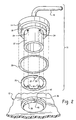
- FIG. 2 is an exploded view of the subassembly of the present invention and the access opening in the upper wall of a fuel tank;
- FIG. 3 is a cross-section of a portion of the valve and tank wall showing the valve partially inserted into the access opening;
- FIG. 4 is a view similar to FIG. 3 showing the valve subassembly in the fully installed position
- FIG. 5 is an enlarged view of a portion of the tank wall in the region of the access opening.
- FIG. 6 is a plan view of the blocking ring.
- a preferred form of the invention having a subassembly including the valve is indicated generally at 10; and, the fuel tank wall indicated generally at 12.
- the valve has a body with an annular external mounting flange 14 having a hose fitting 16 preferably extending from the axial face thereof with a reduced diameter of annular portion 18 formed on the undersurface of the flange 14 with an annular seal ring 20 received thereover.
- a further reduced diameter or lower portion 22 extends downwardly from the portion 18 and has at least one, and preferably a plurality, of torque transmitting surfaces which may take the form of axially extending recesses or grooves 24 formed therein in circumferentially spaced arrangement.
- a locking ring 26 preferably formed of spring material preferably has a radial slit 28 formed therethrough rendering the ring discontinuous with one edge thereof inclined to the plane of the ring form an axial lead portion denoted by reference numeral 30.
- the inner periphery of the ring 26 has at least one, and preferably a plurality, of torque transmitting surfaces corresponding to those on the valve and which may take the form of radially inwardly extending tabs or lugs 32 formed thereon, which lugs are each engaged in one of the grooves 24 upon assembly of the ring over the reduced diameter portion 22 of the valve as shown in FIG. 1.
- FIGS. 2 and 5 a portion of the wall of the tank 20 is shown with a vapor barrier layer 34 is shown broken by formation of an annular groove 36 in the outer surface of the tank wall, in the manner of a counterbore, about a smaller diameter access bore 38 formed through the wall of the tank.
- the counterbore or annular groove is formed preferably by machining to provide dimensionally accurate surfaces for installation and sealing of the valve.
- bore 38 and annular groove 36 are formed in the top wall of the tank; however, it will be understood they may be formed in any convenient area of the tank wall appropriate for proper function of the vent valve.
- a radially extending slit 40 which is inclined to the axis of the opening, is formed in the shoulder 42; and, the width of the slit is sufficiently greater than the thickness of the locking ring 26 to permit ease of passage therethrough.
- the subassembly 10 is shown partially installed with the reduced diameter 22 of the valve inserted through the access opening 38 and with the axial lead 30 of the locking ring 26 entered into the slit 40 by an initial rotation of the subassembly 10.
- the recesses or grooves 24 are of sufficient axial length on the reduced diameter 22 of the valve body to enable the necessary axial movement of the lugs 32 engaged therein without disengagement of the lugs 32 from the grooves 24.
- valve is shown completely installed wherein the subassembly 10 has been rotated further from the position of FIG. 3 sufficiently to feed the locking ring 26 entirely through the slit 40 and to position the locking ring inside the tank and engaging the undersurface of the tank wall 12.
- annular sealing ring 20 engages the wall 36 of the access opening and the diameter 18 of the valve to seal therebetween.
- annular seal 20 is shown in dashed outline as sealing against the diameter 36 of the access opening and the shoulder 42 and thus seals the edges of the vapor barrier layer 34 in the tank wall.
- the present invention thus provides a vapor vent valve which may, if desired, have a seal ring and locking ring disposed therewith forming a subassembly to facilitate installation.
- the valve Upon insertion of the lower portion of the valve into an access opening in a fuel tank, the valve is positively retained and sealed therein by rotation of the valve to feed the locking ring through a slit formed in the access open of the tank wall. Thereafter the locking ring engages the inner surface of the tank wall and the valve to retain the valve in the installed position.
- the valve of the present invention is thus capable of simple mechanical installation, locking and being sealed into a fuel tank access opening without the need for separate fasteners or tools.
Landscapes
- Engineering & Computer Science (AREA)
- Life Sciences & Earth Sciences (AREA)
- Sustainable Development (AREA)
- Sustainable Energy (AREA)
- Chemical & Material Sciences (AREA)
- Combustion & Propulsion (AREA)
- Transportation (AREA)
- Mechanical Engineering (AREA)
- Cooling, Air Intake And Gas Exhaust, And Fuel Tank Arrangements In Propulsion Units (AREA)
- Self-Closing Valves And Venting Or Aerating Valves (AREA)
- Supplying Secondary Fuel Or The Like To Fuel, Air Or Fuel-Air Mixtures (AREA)
Claims (14)
- Procédé de montage et de scellement d'une soupape de mise à l'air libre de vapeur à travers une ouverture d'accès dans la partie supérieure d'un réservoir de carburant, comprenant :(a) la formation d'au moins un évidement (24) sur la périphérie d'une première partie de la soupape en vue d'une extension dans ladite ouverture,(b) la disposition d'une bague d'étanchéité souple annulaire (20) sur la soupape,(c) le dépôt d'un ressort annulaire (26) sur la soupape et l'introduction dans ledit au moins un évidement (24) de certaines parties (32) dudit ressort et l'empêchement d'une rotation relative entre ceux-ci et l'autorisation d'un mouvement axial limité du ressort (26) sur la soupape,(d) la formation d'un épaulement annulaire (42) dans l'ouverture d'accès du réservoir et la formation d'une fente (40) dans l'épaulement et l'insertion de ladite première partie (22) de la soupape dans l'ouverture d'accès et l'engagement d'une extrémité (30) dudit ressort de ladite fente (40), et(e) la rotation de la soupape depuis l'extérieur du réservoir et l'avance dudit ressort (26) à travers ladite fente (40) jusqu'à ce que le ressort traverse ladite fente et soit complètement à l'intérieur du réservoir, et(f) la fermeture hermétique de ladite ouverture d'accès avec ladite bague d'étanchéité (20) et le maintien de ladite soupape dans ladite ouverture d'accès à l'aide dudit ressort.
- Procédé selon la revendication 1, dans lequel ladite étape de formation d'au moins un évidement comprend la formation d'une pluralité d'évidements (24) suivant un agencement espacé sur la circonférence.
- Procédé selon la revendication 1, dans lequel ladite étape de dépôt d'un ressort annulaire comprend le dépôt d'un ressort annulaire discontinu sensiblement plat.
- Procédé selon la revendication 1, dans lequel ladite étape d'engagement dudit au moins un évidement comprend la formation d'une saillie s'étendant radialement vers l'intérieur sur ledit ressort.
- Procédé selon la revendication 1, dans lequel ladite étape de formation d'au moins un évidement comprend la formation d'une pluralité d'évidements suivant un agencement espacé sur la circonférence et ladite étape d'engagement comprend la formation d'une pluralité de saillies s'étendant radialement vers l'intérieur sur ledit ressort et engageant chacun desdits évidements avec l'une desdites saillies.
- Procédé selon la revendication 1, dans lequel l'étape de formation d'un épaulement annulaire comprend le retrait d'un matériau et l'exposition d'une zone annulaire d'une couche imperméable à la vapeur du réservoir et l'étape de scellement de l'ouverture d'accès comprend la mise en contact de ladite région exposée de ladite couche imperméable avec ladite bague d'étanchéité annulaire.
- Procédé selon la revendication 6, dans lequel l'étape de retrait du matériau comprend un usinage.
- Procédé selon la revendication 1, dans lequel ladite étape de scellement comprend le dépôt de ladite bague d'étanchéité souple dans l'épaulement annulaire.
- Montage par verrouillage à came à faible pénétration d'une soupape de mise à l'air libre de vapeur à travers une ouverture d'accès dans la paroi supérieure d'un réservoir de carburant en matière plastique, comprenant :(a) un corps de soupape de mise à l'air libre comportant une sortie (16) pour une communication de vapeur de carburant à travers celle-ci à l'extérieur de la partie de purge actionnée par flotteur du réservoir pour une insertion dans ladite ouverture du réservoir, ledit corps de soupape comportant au moins un évidement (24) formé sur sa périphérie,(b) un élément de ressort annulaire (26) comportant des première et seconde extrémités périphériques reçues sur ledit corps de soupape, des parties (32) dudit ressort s'engageant dans ledit évidement (24) et empêchant une rotation relative dudit ressort par rapport audit corps, ledit évidement permettant un mouvement axial limité dudit ressort,(c) une collerette annulaire (42) formée sur la périphérie de l'ouverture d'accès en ayant une fente (40) dans ladite collerette,(d) un joint annulaire (20) disposé autour dudit corps, où lors de l'insertion dudit corps de soupape dans ladite ouverture d'accès, ledit joint annulaire (20) réalise une étanchéité entre ledit corps et la périphérie de ladite ouverture d'accès, et lors de la rotation dudit corps de soupape dans celle-ci, ladite première extrémité (30) dudit ressort (26) s'engage dans ladite fente (40), et lors d'une rotation supplémentaire de celui-ci, ledit ressort (26) avance à travers ladite fente et ladite seconde extrémité passe à travers ladite fente et ledit ressort s'aligne contre la surface intérieure de ladite paroi supérieure du réservoir (12) maintenant ladite soupape dans ladite ouverture.
- Montage selon la revendication 9, dans lequel le bord d'une couche d'arrêt imperméable à la vapeur (34) d'un matériau est exposé sur la périphérie de ladite ouverture d'accès et mis au contact dudit joint annulaire (20).
- Montage selon la revendication 10, dans lequel ledit bord exposé de ladite couche d'arrêt imperméable est formé en retirant le matériau de ladite ouverture d'accès.
- Montage selon la revendication 9, dans lequel ledit ressort (26) présente une configuration annulaire plate relativement mince.
- Montage selon la revendication 9, dans lequel ledit joint annulaire (20) est formé d'un matériau élastomère.
- Montage selon la revendication 9, dans lequel ladite première extrémité (30) dudit ressort est formée en biais.
Applications Claiming Priority (2)
| Application Number | Priority Date | Filing Date | Title |
|---|---|---|---|
| US09/990,057 US6637778B2 (en) | 2001-11-21 | 2001-11-21 | Low permeation cam lock for plastic fuel tank vapor vent valve |
| US990057 | 2001-11-21 |
Publications (2)
| Publication Number | Publication Date |
|---|---|
| EP1314603A1 EP1314603A1 (fr) | 2003-05-28 |
| EP1314603B1 true EP1314603B1 (fr) | 2004-11-03 |
Family
ID=25535713
Family Applications (1)
| Application Number | Title | Priority Date | Filing Date |
|---|---|---|---|
| EP02024861A Expired - Lifetime EP1314603B1 (fr) | 2001-11-21 | 2002-11-08 | Fermeture à cames à faible perméabilité pour soupape d'évacuation de vapeurs pour réservoir de carburant en matière plastique |
Country Status (9)
| Country | Link |
|---|---|
| US (1) | US6637778B2 (fr) |
| EP (1) | EP1314603B1 (fr) |
| JP (1) | JP2003182390A (fr) |
| KR (1) | KR20030041823A (fr) |
| BR (1) | BR0205044A (fr) |
| CA (1) | CA2411079A1 (fr) |
| DE (1) | DE60201807T2 (fr) |
| MX (1) | MXPA02011452A (fr) |
| TW (1) | TW567157B (fr) |
Families Citing this family (16)
| Publication number | Priority date | Publication date | Assignee | Title |
|---|---|---|---|---|
| US6915812B2 (en) * | 2000-09-12 | 2005-07-12 | Alfmeier Corporation | Low permeation weldable fuel tank assembly |
| JP2005510849A (ja) * | 2001-11-21 | 2005-04-21 | バル・シール・エンジニアリング・カンパニー・インコーポレーテッド | 工具を使用せずに接続及び接続解除を行える係脱可能で導電能力を備えたコネクタ |
| US6966330B2 (en) | 2003-08-27 | 2005-11-22 | Alfmeier Corporation | Weldring with locking arrangement for valve assembly |
| US7146730B2 (en) * | 2003-09-15 | 2006-12-12 | Eaton Corporation | Mounting a pass-through on a plastic fuel tank |
| FR2869842B1 (fr) * | 2004-05-07 | 2007-07-06 | Inergy Automotive Systems Res | Dispositif pour la fixation d'un composant sur un corps creux, methode de fixation associee, reservoir a carburant |
| US7882823B2 (en) * | 2006-02-13 | 2011-02-08 | Eaton Corporation | Double shut-off refueling valve |
| KR100887821B1 (ko) | 2007-11-06 | 2009-03-09 | 현대자동차주식회사 | 가변 흡기계의 진공 탱크 |
| US20090127805A1 (en) * | 2007-11-20 | 2009-05-21 | Eaton Corporation | Assembly for Sealing a Component and Method |
| ES2656521T3 (es) * | 2010-05-06 | 2018-02-27 | YAPP USA Automotive Systems, Inc. | Tanque de combustible de vehículo |
| US9994101B2 (en) | 2010-05-06 | 2018-06-12 | Jeff Yager | Vehicle fuel tank |
| US8807601B2 (en) * | 2011-03-01 | 2014-08-19 | Evergreen Tool Co., Inc. | Compression seal assembly |
| US9599076B2 (en) | 2011-03-03 | 2017-03-21 | Denso International America, Inc. | Fuel tank locking ring mounted fuel pump controller |
| US9102445B2 (en) * | 2011-04-27 | 2015-08-11 | Caterpillar Inc. | Tank assembly having twist-and-lock mounting flange |
| JP2014024370A (ja) * | 2012-07-24 | 2014-02-06 | Yachiyo Industry Co Ltd | 中空容器及び中空容器製造装置 |
| DE102015006375B3 (de) * | 2015-05-20 | 2016-09-15 | Audi Ag | Brennkraftmaschine |
| WO2020110311A1 (fr) * | 2018-11-30 | 2020-06-04 | 本田技研工業株式会社 | Structure de fixation d'unité d'arrêt de carburant |
Family Cites Families (20)
| Publication number | Priority date | Publication date | Assignee | Title |
|---|---|---|---|---|
| US477308A (en) * | 1892-06-21 | Faucet | ||
| US766083A (en) * | 1903-06-25 | 1904-07-26 | Alfred Monsell Sprainger Watts | Means for attaching draw-off taps to drums, &c. |
| US1062635A (en) * | 1911-03-08 | 1913-05-27 | Clements Co | Attachment for sheet-metal constructions. |
| US1159685A (en) * | 1913-01-28 | 1915-11-09 | Henry B Killefer | Faucet. |
| US1319124A (en) * | 1918-08-14 | 1919-10-21 | Abner G Showers | Tank connection. |
| US1398083A (en) * | 1919-12-15 | 1921-11-22 | Elmer S Stack | Pipe-coupling |
| US1401584A (en) * | 1920-05-04 | 1921-12-27 | Albert F Cizek | Conduit device for tapping cans |
| US2241793A (en) * | 1934-08-02 | 1941-05-13 | American Flange & Mfg | Bung or discharge hole formation in a sheet metal container wall |
| US2411761A (en) * | 1945-06-09 | 1946-11-26 | Russell Electric Company | Retaining washer and the like |
| US3347293A (en) * | 1965-12-23 | 1967-10-17 | Magna Driver Corp | Removable bit construction for screwdrivers and the like |
| US3477745A (en) * | 1968-03-11 | 1969-11-11 | Allied Insulation Co | Quick connection of pipe to ducting |
| US3650551A (en) * | 1971-02-08 | 1972-03-21 | Borg Warner | Self-sealing tank connector |
| US3915477A (en) * | 1974-05-03 | 1975-10-28 | Automation Ind Inc | Duct fitting |
| US4343581A (en) * | 1979-05-21 | 1982-08-10 | Waldes Kohinoor, Inc. | Double-bevel spring retaining ring |
| US4906150A (en) * | 1985-07-17 | 1990-03-06 | Bennett Bruce A | Locking fastener |
| US5083583A (en) | 1990-09-04 | 1992-01-28 | G.T. Products, Inc. | Fuel tank vapor vent valve and seal |
| JP3741798B2 (ja) | 1996-01-31 | 2006-02-01 | 日産自動車株式会社 | 液面検知用バルブ |
| US6212746B1 (en) * | 1999-10-27 | 2001-04-10 | Hill-Rom, Inc. | Retaining ring installation apparatus |
| US6379130B1 (en) * | 2000-06-09 | 2002-04-30 | Tecumseh Products Company | Motor cover retention |
| US6520545B2 (en) * | 2000-12-08 | 2003-02-18 | Sartorius Ag | Fluid connection adapter assembly |
-
2001
- 2001-11-21 US US09/990,057 patent/US6637778B2/en not_active Expired - Lifetime
-
2002
- 2002-10-25 TW TW091124982A patent/TW567157B/zh active
- 2002-11-04 CA CA002411079A patent/CA2411079A1/fr not_active Abandoned
- 2002-11-08 DE DE60201807T patent/DE60201807T2/de not_active Expired - Lifetime
- 2002-11-08 EP EP02024861A patent/EP1314603B1/fr not_active Expired - Lifetime
- 2002-11-15 JP JP2002332306A patent/JP2003182390A/ja not_active Withdrawn
- 2002-11-20 KR KR1020020072267A patent/KR20030041823A/ko not_active Withdrawn
- 2002-11-21 MX MXPA02011452A patent/MXPA02011452A/es unknown
- 2002-11-21 BR BR0205044-7A patent/BR0205044A/pt not_active IP Right Cessation
Also Published As
| Publication number | Publication date |
|---|---|
| US20030094763A1 (en) | 2003-05-22 |
| DE60201807D1 (de) | 2004-12-09 |
| EP1314603A1 (fr) | 2003-05-28 |
| KR20030041823A (ko) | 2003-05-27 |
| US6637778B2 (en) | 2003-10-28 |
| TW567157B (en) | 2003-12-21 |
| CA2411079A1 (fr) | 2003-05-21 |
| DE60201807T2 (de) | 2005-10-27 |
| MXPA02011452A (es) | 2003-05-30 |
| JP2003182390A (ja) | 2003-07-03 |
| BR0205044A (pt) | 2003-09-16 |
Similar Documents
| Publication | Publication Date | Title |
|---|---|---|
| US6637778B2 (en) | Low permeation cam lock for plastic fuel tank vapor vent valve | |
| US6182693B1 (en) | Vapor canister and fuel tank assembly | |
| US6502607B2 (en) | Fuel tank valve apparatus | |
| CA1091189A (fr) | Bouchon pour reservoir d'essence | |
| US20090107583A1 (en) | Fill Nozzle Positioning Apparatus | |
| US20060011234A1 (en) | Fuel vapor vent valve float assembly and method of making same | |
| US7146730B2 (en) | Mounting a pass-through on a plastic fuel tank | |
| EP1247034B1 (fr) | Appareil a clapet de stockage de carburant | |
| US7146729B2 (en) | Fuel vapor vent valve and method of attaching same to a tank | |
| US5601205A (en) | Fuel tank assembly | |
| US6584996B2 (en) | Installing a valve in a tank | |
| CA1182427A (fr) | Soupape a pression pour bouchon de remplissage de reservoir d'essence | |
| US9994101B2 (en) | Vehicle fuel tank | |
| US7083062B2 (en) | Orientationless internal closure/retainer and valve assembly employing same | |
| JPH0363760U (fr) | ||
| AU2002318017A1 (en) | Installing a valve in a tank |
Legal Events
| Date | Code | Title | Description |
|---|---|---|---|
| PUAI | Public reference made under article 153(3) epc to a published international application that has entered the european phase |
Free format text: ORIGINAL CODE: 0009012 |
|
| AK | Designated contracting states |
Designated state(s): AT BE BG CH CY CZ DE DK EE ES FI FR GB GR IE IT LI LU MC NL PT SE SK TR |
|
| AX | Request for extension of the european patent |
Extension state: AL LT LV MK RO SI |
|
| 17P | Request for examination filed |
Effective date: 20030620 |
|
| AKX | Designation fees paid |
Designated state(s): DE FR GB IT NL SE |
|
| GRAP | Despatch of communication of intention to grant a patent |
Free format text: ORIGINAL CODE: EPIDOSNIGR1 |
|
| GRAS | Grant fee paid |
Free format text: ORIGINAL CODE: EPIDOSNIGR3 |
|
| GRAA | (expected) grant |
Free format text: ORIGINAL CODE: 0009210 |
|
| AK | Designated contracting states |
Kind code of ref document: B1 Designated state(s): DE FR GB IT NL SE |
|
| REG | Reference to a national code |
Ref country code: GB Ref legal event code: FG4D |
|
| REG | Reference to a national code |
Ref country code: SE Ref legal event code: TRGR |
|
| REF | Corresponds to: |
Ref document number: 60201807 Country of ref document: DE Date of ref document: 20041209 Kind code of ref document: P |
|
| REG | Reference to a national code |
Ref country code: IE Ref legal event code: FG4D |
|
| ET | Fr: translation filed | ||
| PLBE | No opposition filed within time limit |
Free format text: ORIGINAL CODE: 0009261 |
|
| STAA | Information on the status of an ep patent application or granted ep patent |
Free format text: STATUS: NO OPPOSITION FILED WITHIN TIME LIMIT |
|
| 26N | No opposition filed |
Effective date: 20050804 |
|
| PGFP | Annual fee paid to national office [announced via postgrant information from national office to epo] |
Ref country code: FR Payment date: 20051104 Year of fee payment: 4 |
|
| PGFP | Annual fee paid to national office [announced via postgrant information from national office to epo] |
Ref country code: SE Payment date: 20051107 Year of fee payment: 4 |
|
| PG25 | Lapsed in a contracting state [announced via postgrant information from national office to epo] |
Ref country code: SE Free format text: LAPSE BECAUSE OF NON-PAYMENT OF DUE FEES Effective date: 20061109 |
|
| PGFP | Annual fee paid to national office [announced via postgrant information from national office to epo] |
Ref country code: IT Payment date: 20061130 Year of fee payment: 5 |
|
| PG25 | Lapsed in a contracting state [announced via postgrant information from national office to epo] |
Ref country code: NL Free format text: LAPSE BECAUSE OF NON-PAYMENT OF DUE FEES Effective date: 20070601 |
|
| EUG | Se: european patent has lapsed | ||
| GBPC | Gb: european patent ceased through non-payment of renewal fee |
Effective date: 20061108 |
|
| NLV4 | Nl: lapsed or anulled due to non-payment of the annual fee |
Effective date: 20070601 |
|
| REG | Reference to a national code |
Ref country code: FR Ref legal event code: ST Effective date: 20070731 |
|
| PG25 | Lapsed in a contracting state [announced via postgrant information from national office to epo] |
Ref country code: GB Free format text: LAPSE BECAUSE OF NON-PAYMENT OF DUE FEES Effective date: 20061108 |
|
| PG25 | Lapsed in a contracting state [announced via postgrant information from national office to epo] |
Ref country code: FR Free format text: LAPSE BECAUSE OF NON-PAYMENT OF DUE FEES Effective date: 20061130 |
|
| PG25 | Lapsed in a contracting state [announced via postgrant information from national office to epo] |
Ref country code: IT Free format text: LAPSE BECAUSE OF NON-PAYMENT OF DUE FEES Effective date: 20071108 |
|
| PGFP | Annual fee paid to national office [announced via postgrant information from national office to epo] |
Ref country code: DE Payment date: 20181023 Year of fee payment: 17 |
|
| REG | Reference to a national code |
Ref country code: DE Ref legal event code: R082 Ref document number: 60201807 Country of ref document: DE Ref country code: DE Ref legal event code: R081 Ref document number: 60201807 Country of ref document: DE Owner name: EATON INTELLIGENT POWER LIMITED, IE Free format text: FORMER OWNER: EATON CORP., CLEVELAND, OHIO, US |
|
| REG | Reference to a national code |
Ref country code: DE Ref legal event code: R119 Ref document number: 60201807 Country of ref document: DE |
|
| PG25 | Lapsed in a contracting state [announced via postgrant information from national office to epo] |
Ref country code: DE Free format text: LAPSE BECAUSE OF NON-PAYMENT OF DUE FEES Effective date: 20200603 |