EP1314675B1 - Détecteur de charge pour une cabine d'ascenseur - Google Patents
Détecteur de charge pour une cabine d'ascenseur Download PDFInfo
- Publication number
- EP1314675B1 EP1314675B1 EP03003118A EP03003118A EP1314675B1 EP 1314675 B1 EP1314675 B1 EP 1314675B1 EP 03003118 A EP03003118 A EP 03003118A EP 03003118 A EP03003118 A EP 03003118A EP 1314675 B1 EP1314675 B1 EP 1314675B1
- Authority
- EP
- European Patent Office
- Prior art keywords
- cage
- load
- sheave
- strain
- shaft
- Prior art date
- Legal status (The legal status is an assumption and is not a legal conclusion. Google has not performed a legal analysis and makes no representation as to the accuracy of the status listed.)
- Expired - Lifetime
Links
- 238000010276 construction Methods 0.000 claims description 7
- 238000006073 displacement reaction Methods 0.000 description 1
- 230000000694 effects Effects 0.000 description 1
- 238000005259 measurement Methods 0.000 description 1
- 238000000034 method Methods 0.000 description 1
- 238000012986 modification Methods 0.000 description 1
- 230000004048 modification Effects 0.000 description 1
Images




Classifications
-
- B—PERFORMING OPERATIONS; TRANSPORTING
- B66—HOISTING; LIFTING; HAULING
- B66B—ELEVATORS; ESCALATORS OR MOVING WALKWAYS
- B66B1/00—Control systems of elevators in general
-
- B—PERFORMING OPERATIONS; TRANSPORTING
- B66—HOISTING; LIFTING; HAULING
- B66B—ELEVATORS; ESCALATORS OR MOVING WALKWAYS
- B66B1/00—Control systems of elevators in general
- B66B1/34—Details, e.g. call counting devices, data transmission from car to control system, devices giving information to the control system
- B66B1/3476—Load weighing or car passenger counting devices
-
- B—PERFORMING OPERATIONS; TRANSPORTING
- B66—HOISTING; LIFTING; HAULING
- B66B—ELEVATORS; ESCALATORS OR MOVING WALKWAYS
- B66B7/00—Other common features of elevators
Definitions
- the present invention relates to a load detector for an elevator cage.
- An ordinary traction type elevator is composed as shown in FIG. 1 and FIG. 2.
- one terminal of a cable 2 is connected to a cage 1 and the other terminal of the cable 2 is connected to a counter weight via a sheave 31 of a hoisting machine 3 and deflector sheave 4.
- the hoisting machine is composed of the sheave 31 and a motor 32.
- the sheave 31 is driven by the motor 32, and the cable 2 is driven by the traction between the sheave 31 and the cable 2.
- the cage 1 is moved up and down via the cable 2.
- the cage 1 moves up and down along guide rails 7 by means of guide devices 6 attached to the cage 1.
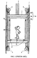
- the cage 1 is composed of a cage frame 1A including a crosshead 1Aa, an upright 1Ab and a plank 1Ac, and a cab 1B mounted in the cage frame 1A. That is, construction of the cage 1 is in effect doubled by providing the cage frame 1A around the cab 1B, and the cab 1B is supported by vibration-proof materials 1C such as a rubber.
- the vibration-proof materials 1C reduce vibration transfer from the cage frame 1A to the cab 1B and improve passenger comfort during travel of the cage 1.
- a deformation detector 1D is installed between the cage frame 1A and the cab 1B.
- the vibration-proof materials 1C is pressed by the load of the cab 1B, and the amount of the deformation of the vibration-proof materials 1C is detected by the deformation detector 1D.
- the amount of the deformation is transmitted to a calculator 11 in an elevator control panel via a transmitting cable 8, a connector box 91 attached on a shaft wall 9a of a shaft 9, and a transmitter 10.
- the calculator 11 calculates the load of the cab 1B or the load of passengers on the basis of the amount of the deformation from the deformation detector 1D.
- the calculator 11 also calculates a necessary torque to drive the motor 32 so as to move the cage 1 smoothly at the start time, and outputs the torque signal to a drive controller 12. Accordingly, even if the cage 1 is filled with many passengers, the cage 1 does not move down suddenly at the start time when a brake is off. On the other hand, even if the cage 1 has no passengers, the cage 1 does not move up suddenly at the start time. That is, the drive controller 12 applies a necessary torque to the motor 32 before the brake is off so as to move the cage 1 smoothly at the start time.
- both the cage frame 1A and the cab 1B need a proper strength. It is not easy for the cage 1 to meet both the requirements of the proper strength and the capacity of the cab 1B.
- the deformation detector 1D can not be installed between the cage frame 1A and the cab 1B.
- the elevator has difficulty in controlling the torque applied to the motor 32 at the start time in accordance with change in the load.
- EP-A-0 755 894 there is described a method and apparatus for the measurement of a load in an elevator cage supported by spring elements mounted to a carrying frame and moveable in an elevated shaft by a hoist cable guided over a drive pulley.
- the elevator is of a double construction with a cage and a carrying frame.
- JP 09 240942 there is disclosed a pin type load cell used as a main shaft of a sheave for a car of an elevator system and is constituted so as to detect a load in a main shaft part.
- an object of the invention is to provide a load detector for an elevator which can detect the passenger load if a cab is integrated with a cage frame.
- a load detector for an elevator having a cable placed around a sheave driven by a motor, said cable hanging a cage, which is constructed in a single construction, whereby a cab is integrated with a cage frame, through a hanging sheave attached to said cage moving up and down in a shaft for transporting passengers, comprising: a strain detector configured to detect a strain of a rotary shaft of said sheave; and a calculator configured to calculate a change of a strain of said sheave just after said cage lands at a floor and a strain of said sheave just before said cage leaves said floor, and a load of said cage on the basis of said change of said strain.
- FIG. 3 is a side view of a traction type elevator having hanging sheaves.
- the cage 1 has a "single" construction, that is to say, the cab is integrated with the cage frame.
- One end of the cable 2 is secured to a hitch 2B at an upper portion of the shaft 9.
- the other end of the cable 2 is secured to a hitch 2A via the counter weight 5, the hoisting machine 3, and hanging sheaves 1C of the cage 1.
- the cable 2 is driven by the hoisting machine 3, and the cage 1 and the counter weight 5 relatively move up and down.
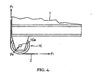
- a tension F 1 corresponding to a load of the cage 1 is applied to a shaft 1Ca of the hanging sheave I C.
- a change of the tension F 1 corresponds to a load change of the cage 1. Consequently, a change of a force F2 applied to the shaft 1 Ca corresponds to a load change of the cage 1.
- FIG. 5 is a sectional view of a hanging sheave showing a load detector for an elevator cage of a first embodiment of the present invention, in which the load detector detects a change of the force F2 applied to the shaft 1Ca by means of a strain gage.
- the shaft 1Ca (only one is shown) is rotatably secured to the cage 1 via a bearing 1Cc, and the shaft 1Ca is supported by support members 1Cd on the cage 1.
- Strain gages 1Ce are built in the shaft 1Ca near the bearing 1Cc so as to detect a strain caused by a force F2 applied to the rotary shaft via the bearing 1Cc.
- Output signals of the strain gages I Ce are transmitted to the calculator 11 via the transmitting cable 8 shown in FIG. 1.
- the calculator I 1 calculates a load change of the cage 1 on the basis of a change of a force F2 applied to the shaft 1Ca, and then calculates a load of the cage 1.
- the calculator 11 calculates a necessary torque to drive the motor 32 so as to start the cage 1 smoothly on the basis of the load of the cage 1.
- FIG. 6 is a sectional view of a rotary shaft showing a load detector for an elevator cage of a second embodiment of the present invention.
- a load of the cage 1 is calculated on the basis of a force F2 applied to the shaft 1Ca and detected by the strain gages 1Ce built in the shaft 1Ca, while in FIG. 6, a load of the cage 1 is calculated on the basis of a strain of elastic members I Cf lying between the shaft 1Ca and the cage 1 instead of the support members 1Cd in FIG. 5.
- a force F2 is applied to the cage via the bearing 1Cc, the shaft 1Ca and the elastic members 1Cf.
- the elastic members 1Cf deforms by a load change of the cage 1.
- the deformation of the elastic members 1Cf is detected by a potential meter 1Cg, i.e., a differential transformer which transforms displacement into electric resistance, attached in parallel to one of the elastic members 1Cf.
- An output signal of the potential meter 1Cg is transmitted to the calculator 11 via the transmitting cable 8.
- the calculator 11 calculates a load change of the cage 1 on the basis of a change of a force F2 applied to the shaft 1Ca, and then calculates a load of the cage 1.
- the calculator 11 calculates a necessary torque to drive the motor 32 so as to start the cage 1 smoothly on the basis of the load of the cage 1.
- the calculator 11 is configured to calculate a change of strain of the hanging sheave 1C just after the cage lands at a floor and a strain of the hanging sheave just before the cage leaves that floor.
- a load detector is installed at the hanging sheave 1C, a load of the cage 1 is detected precisely.
- FIG. 7 is a side view of a sheave showing a load detector for an elevator cage of a third embodiment of the present invention.
- the hoisting machine 3 is arranged on a shaft ceiling wall 9b via two elastic members 31c.
- a potential meter 31d is attached in parallel to one of the elastic members 31c.
- the potential meter 31d outputs a voltage signal corresponding to a deformation of the elastic member 31c.
- An output signal of the potention meter 31d is transmitted to the calculator 1 via the transmitting cable 8.
- a force F3 applied to the rotary shaft 31a of the sheave 31 is based on the sum of a load of the cage 1, a load of the counter weight, a load of the cable 2 and a load of the hoisting machine 3. Above all, the load of the cage 1 is the only item to be changeable.
- a load change of the cage 1 is calculated on the basis of a deformation of the elastic member 31c detected by the potential meter 31d.
- the calculator 11 calculates a load of the cage 1 on the basis of the load change of the cage 1.
- the calculator 11 calculates a necessary torque to drive the motor 32 so as to start the cage 1 smoothly on the basis of the load of the cage 1.
- the calculator 11 is configured to calculate a change of strain of the sheave 31 just after the cage 1 lands at a floor and a strain of the sheave 31 just before the cage leaves that floor.
Landscapes
- Engineering & Computer Science (AREA)
- Automation & Control Theory (AREA)
- Mechanical Engineering (AREA)
- Computer Networks & Wireless Communication (AREA)
- Elevator Control (AREA)
- Maintenance And Inspection Apparatuses For Elevators (AREA)
- Indicating And Signalling Devices For Elevators (AREA)
- Cage And Drive Apparatuses For Elevators (AREA)
Claims (2)
- Détecteur de charge pour un ascenseur, ayant un câble (2) placé autour d'une poulie (31) entraînée par un moteur électrique (32), ledit câble suspendant une cabine d'ascenseur (1) qui est construit en une seule structure, dans laquelle une cabine (1B) est intégrée à un bâti de cabine d'ascenseur (1A), par l'intermédiaire d'une poulie de suspension (1C) attachée à ladite cabine d'ascenseur se déplaçant selon un mouvement ascendant et descendant dans une cage (9), pour transporter des personnes, comprenant :un détecteur de sollicitations (31c, 31d), configuré pour détecter une sollicitation d'un arbre rotatif (31a) de ladite poulie (31) ; etun calculateur (11) configuré pour calculer un changement d'une sollicitation de ladite poulie (31) juste après que ladite cabine d'ascenseur est arrivée au niveau d'un palier, et d'une sollicitation de ladite poulie juste avant que ladite cabine d'ascenseur ne quitte ledit palier, et une charge de ladite cabine d'ascenseur, sur la base de dudit changement de ladite sollicitation.
- Détecteur de charge pour un ascenseur, ayant un câble (2) placé autour d'une poulie (31) entraînée par un moteur électrique (32), ledit câble suspendant une cabine d'ascenseur qui est construit en une seule structure, dans laquelle une cabine (1B) est intégrée à un bâti de cabine d'ascenseur (1A), par l'intermédiaire d'une poulie de suspension (1C) attachée à ladite cabine d'ascenseur se déplaçant selon un mouvement ascendant et descendant dans une cage (9), pour transporter des personnes, comprenant :un détecteur de sollicitations (1Ce ; 1Cf, 1Cg), configuré pour détecter une sollicitation d'un arbre (1Ca) de ladite poulie de suspension (1C) ; etun calculateur (11) configuré pour calculer un changement d'une sollicitation de ladite poulie de suspension (1C) juste après que ladite cabine d'ascenseur est arrivée au niveau d'un palier, et d'une sollicitation de ladite poulie de suspension juste avant que ladite cabine d'ascenseur ne quitte ledit palier, et une charge de ladite cabine d'ascenseur, sur la base dudit changement de ladite sollicitation.
Applications Claiming Priority (3)
| Application Number | Priority Date | Filing Date | Title |
|---|---|---|---|
| JP11949598 | 1998-04-28 | ||
| JP10119495A JPH11314868A (ja) | 1998-04-28 | 1998-04-28 | 昇降機のかご荷重検出装置 |
| EP99107382A EP0953537B1 (fr) | 1998-04-28 | 1999-04-23 | Capteur de charge pour une cabine d'ascenseur |
Related Parent Applications (1)
| Application Number | Title | Priority Date | Filing Date |
|---|---|---|---|
| EP99107382A Division EP0953537B1 (fr) | 1998-04-28 | 1999-04-23 | Capteur de charge pour une cabine d'ascenseur |
Publications (2)
| Publication Number | Publication Date |
|---|---|
| EP1314675A1 EP1314675A1 (fr) | 2003-05-28 |
| EP1314675B1 true EP1314675B1 (fr) | 2006-03-22 |
Family
ID=14762690
Family Applications (2)
| Application Number | Title | Priority Date | Filing Date |
|---|---|---|---|
| EP99107382A Expired - Lifetime EP0953537B1 (fr) | 1998-04-28 | 1999-04-23 | Capteur de charge pour une cabine d'ascenseur |
| EP03003118A Expired - Lifetime EP1314675B1 (fr) | 1998-04-28 | 1999-04-23 | Détecteur de charge pour une cabine d'ascenseur |
Family Applications Before (1)
| Application Number | Title | Priority Date | Filing Date |
|---|---|---|---|
| EP99107382A Expired - Lifetime EP0953537B1 (fr) | 1998-04-28 | 1999-04-23 | Capteur de charge pour une cabine d'ascenseur |
Country Status (7)
| Country | Link |
|---|---|
| US (1) | US6305503B1 (fr) |
| EP (2) | EP0953537B1 (fr) |
| JP (1) | JPH11314868A (fr) |
| KR (1) | KR100427462B1 (fr) |
| CN (1) | CN1091420C (fr) |
| DE (2) | DE69930426T2 (fr) |
| MY (1) | MY122423A (fr) |
Families Citing this family (58)
| Publication number | Priority date | Publication date | Assignee | Title |
|---|---|---|---|---|
| FI981887A7 (fi) * | 1998-09-04 | 2000-03-05 | Kone Corp | Hissijärjestely hissikoneiston moottorin lähtömomentin asettamiseksi |
| JP4270657B2 (ja) * | 1999-07-06 | 2009-06-03 | 東芝エレベータ株式会社 | エレベータ案内装置 |
| RU2271327C2 (ru) * | 2000-05-01 | 2006-03-10 | Инвенцио Аг | Грузоподъемное приспособление для канатных лифтов со встроенным грузоизмерительным устройством |
| US6483047B1 (en) * | 2000-09-13 | 2002-11-19 | Otis Elevator Company | Elevator brake load weighing system |
| US6450299B1 (en) * | 2000-09-14 | 2002-09-17 | C.E. Electronics, Inc. | Load measuring for an elevator car |
| US6488128B1 (en) * | 2000-12-12 | 2002-12-03 | Otis Elevator Company | Integrated shaft sensor for load measurement and torque control in elevators and escalators |
| DE10164236A1 (de) * | 2001-12-27 | 2003-07-17 | Bsh Bosch Siemens Hausgeraete | Hocheinbaugargerät |
| AU2002368168A1 (en) * | 2002-10-08 | 2004-05-04 | Otis Elevator Company | Elevator cab locating system including wireless communication |
| US7077244B2 (en) * | 2002-10-08 | 2006-07-18 | Otis Elevator Company | Elevator cab locating system including wireless communication |
| GB2395003B (en) | 2002-10-30 | 2005-01-26 | Airdri Ltd | Sensory system for a lift door |
| AU2002365061A1 (en) * | 2002-12-27 | 2004-07-22 | Otis Elevator Company | Elevator machine with direct shaft torque sensing |
| DE10297848T5 (de) * | 2002-12-30 | 2005-10-27 | Otis Elevator Co., Farmington | Positionsreferenzierungssystem |
| US20060232789A1 (en) * | 2002-12-30 | 2006-10-19 | Jae-Hyuk Oh | Position referencing system |
| EP1594786A4 (fr) * | 2003-02-03 | 2011-06-22 | Otis Elevator Co | Referentiel passif de positionnement d'un ascenseur au moyen de signaux ultrasonores et de signaux rf |
| US7493991B2 (en) * | 2003-05-30 | 2009-02-24 | Otis Elevator Company | Electromagnetic/ultrasonic roll-calling/answering (EURA) system for elevator positioning |
| WO2005052842A2 (fr) | 2003-10-31 | 2005-06-09 | Otis Elevator Company | Systeme de positionnement a base de detecteur a dispositif de transfert de charge faible resolution et d'identification r.f. |
| JP4885884B2 (ja) * | 2005-02-25 | 2012-02-29 | オーチス エレベータ カンパニー | エレベータモータブレーキのトルク測定装置 |
| KR100963357B1 (ko) * | 2005-09-30 | 2010-06-14 | 미쓰비시덴키 가부시키가이샤 | 엘리베이터 장치 |
| FI120763B (fi) * | 2006-06-05 | 2010-02-26 | Kone Corp | Menetelmä kuorman mittaamiseksi hississä ja hissi |
| EP1878683A3 (fr) * | 2006-07-10 | 2009-05-20 | Inventio AG | Dispositif destiné à la détermination de la charge dans une cabine d'ascenseur |
| US7784589B2 (en) * | 2006-07-10 | 2010-08-31 | Inventio Ag | Elevator lift cage load measuring assembly |
| ES2408126T3 (es) * | 2006-08-15 | 2013-06-18 | Otis Elevator Company | Freno de ascensor con cojinete y superficie de freno integrados |
| US20080116017A1 (en) * | 2006-11-20 | 2008-05-22 | Kress James R | Elevator car overload warning system and method |
| FI118639B (fi) * | 2006-12-08 | 2008-01-31 | Kone Corp | Hissijärjestelmä |
| TWI394705B (zh) * | 2007-02-02 | 2013-05-01 | Inventio Ag | 升降機及監視此升降機之方法 |
| CN101298307B (zh) * | 2007-05-03 | 2010-06-23 | 因温特奥股份公司 | 电梯设备,电梯设备用转向辊,和设置负载传感器的方法 |
| JP2009263108A (ja) * | 2008-04-28 | 2009-11-12 | Hitachi Ltd | エレベータの位置検出装置 |
| US8407876B2 (en) | 2008-11-05 | 2013-04-02 | Inventio Ag | Modernization method for elevator installations |
| JP5055333B2 (ja) * | 2009-09-16 | 2012-10-24 | 株式会社日立製作所 | エレベータシステム |
| JP5531648B2 (ja) * | 2010-01-29 | 2014-06-25 | 三菱電機株式会社 | エレベーター制御装置 |
| WO2012031961A1 (fr) * | 2010-09-09 | 2012-03-15 | Inventio Ag | Dispositif de mesure de charge pour une installation d'ascenseur |
| JP5649061B2 (ja) * | 2011-04-11 | 2015-01-07 | 東芝エレベータ株式会社 | エレベータの着床検出装置 |
| EP2524890B1 (fr) * | 2011-05-20 | 2013-08-28 | Kone Corporation | Ascenseur avec force de freinage variable selon la position |
| US9567195B2 (en) * | 2013-05-13 | 2017-02-14 | Hall David R | Load distribution management for groups of motorized lifting devices |
| JP2014234261A (ja) * | 2013-06-03 | 2014-12-15 | 株式会社日立製作所 | エレベーターの荷重検出方法及び荷重検出装置 |
| JP2015124033A (ja) * | 2013-12-26 | 2015-07-06 | 株式会社日立製作所 | エレベータ装置及びその乗りかご内荷重検出方法 |
| US10273119B2 (en) | 2014-09-12 | 2019-04-30 | Otis Elevator Company | Elevator load weighing system |
| DE102014225551A1 (de) * | 2014-12-11 | 2016-06-16 | Thyssenkrupp Ag | Verfahren zum Bestimmen einer Last in einer Kabine eines Aufzugsystems |
| DE102015207796A1 (de) * | 2015-04-28 | 2016-11-17 | Thyssenkrupp Ag | Vorrichtung zur Messung von Lasten in einer Aufzugsanlage |
| JP6776599B2 (ja) * | 2016-04-25 | 2020-10-28 | フジテック株式会社 | エレベータ装置 |
| JP6811058B2 (ja) * | 2016-08-18 | 2021-01-13 | Ihi運搬機械株式会社 | 定位置検出装置とこれを用いたエレベータ式駐車装置 |
| EP3406559A1 (fr) | 2017-05-24 | 2018-11-28 | Otis Elevator Company | Dispositif de transport de personnes |
| JP2019043749A (ja) * | 2017-09-06 | 2019-03-22 | 株式会社日立製作所 | マルチカーエレベーター |
| EP3511278A1 (fr) * | 2018-01-11 | 2019-07-17 | Otis Elevator Company | Système d'ascenseur et procédé de positionnement d'une cabine d'ascenseur avec une précision élevée |
| CN108382941B (zh) * | 2018-03-26 | 2020-10-16 | 日立电梯(中国)有限公司 | 电梯过载检测装置及电梯过载检测方法 |
| EP3556700A1 (fr) * | 2018-04-20 | 2019-10-23 | Inventio AG | Installation d'ascenseur dotée d'un dispositif de mesure de position ainsi que procédé de détermination d'une position d'une cabine d'ascenseur dans une cage d'ascenseur |
| GB2574644B (en) * | 2018-06-13 | 2022-09-07 | Avire Ltd | A location system, method, and calibration method |
| EP3705435B1 (fr) * | 2019-03-05 | 2021-09-15 | KONE Corporation | Élément combiné d'isolation contre les vibrations et de mesure de charge pour ascenseur |
| KR102233399B1 (ko) | 2020-07-23 | 2021-03-26 | 주식회사 티유글로벌 | 작업 효율이 향상된 연마 디스크 및 이의 제조방법 |
| JP7056714B1 (ja) * | 2020-10-09 | 2022-04-19 | フジテック株式会社 | エレベータのかご内積載物荷重検出装置 |
| CN112623893B (zh) * | 2020-12-03 | 2023-04-14 | 深圳市普渡科技有限公司 | 一种电梯楼层确定方法、装置、计算机设备及存储介质 |
| JP7151797B2 (ja) * | 2021-01-06 | 2022-10-12 | フジテック株式会社 | エレベータかご装置及びエレベータ |
| CA3153707A1 (fr) * | 2021-04-13 | 2022-10-13 | Appana Industries LLC | Systemes et methodes pour determiner les charges d'ascenseur |
| CN113401766B (zh) * | 2021-07-23 | 2022-10-04 | 广东长城电梯有限公司 | 电梯轿厢缓冲装置 |
| WO2023232244A1 (fr) * | 2022-06-01 | 2023-12-07 | Kone Corporation | Dispositifs, systèmes, procédés et programmes informatiques pour mesurer un ou plusieurs paramètres de fonctionnement d'un ascenseur |
| KR102484427B1 (ko) | 2022-10-19 | 2023-01-04 | 동양에레베이터 주식회사 | 연결벨트를 이용한 상부 구동형 승강기의 구조 |
| CN115893139A (zh) * | 2022-11-09 | 2023-04-04 | 上海三菱电梯有限公司 | 电梯轿厢称重方法 |
| CN118004849A (zh) * | 2024-03-08 | 2024-05-10 | 上海三菱电梯有限公司 | 电梯启动力矩电流计算方法 |
Family Cites Families (16)
| Publication number | Priority date | Publication date | Assignee | Title |
|---|---|---|---|---|
| US4616321A (en) * | 1979-08-29 | 1986-10-07 | Chan Yun T | Drilling rig monitoring system |
| US4299309A (en) * | 1979-12-27 | 1981-11-10 | Otis Elevator Company | Empty elevator car determination |
| HU188450B (en) * | 1983-04-29 | 1986-04-28 | Vasipari Kutato Es Fejlesztoe Vallalat,Hu | Electromechanic measuring transducer pin |
| JPS6288792A (ja) * | 1985-10-15 | 1987-04-23 | 三菱電機株式会社 | エレベ−タの荷重検出装置 |
| US4674605A (en) * | 1986-04-18 | 1987-06-23 | Otis Elevator Company | Automatic elevator load sensor calibration system |
| US4793442A (en) * | 1987-11-05 | 1988-12-27 | Schindler Elevator Corporation | Method and apparatus for providing pre-travel balancing energy to an elevator drive |
| US5004076A (en) * | 1989-04-18 | 1991-04-02 | Chen Hai C | Apparatus for controlling an electric elevator |
| DE4119253A1 (de) | 1990-06-11 | 1991-12-12 | Mitsubishi Electric Corp | Aufzugssteuervorrichtung |
| US5124626A (en) * | 1990-12-20 | 1992-06-23 | Mts Systems Corporation | Sinusoidal signal amplitude and phase control for an adaptive feedback control system |
| FI94121C (fi) * | 1991-08-15 | 1995-07-25 | Kone Oy | Hissikorin henkilösiirtojen määrittäminen |
| US5156239A (en) * | 1991-12-17 | 1992-10-20 | Otis Elevator Company | Disc brake/load weighing assembly for elevator drive sheave |
| US5306879A (en) * | 1992-01-30 | 1994-04-26 | Inventio Ag | Load measuring apparatus for an elevator car |
| ES2100020T3 (es) * | 1993-03-04 | 1997-06-01 | Otis Elevator Co | Par de polarizacion para motorizacion de un ascensor con el fin de evitar un deslizamiento hacia arriba o hacia abajo. |
| JPH0876845A (ja) * | 1994-09-07 | 1996-03-22 | Hitachi Maxell Ltd | 自動搬送装置 |
| ATE199699T1 (de) * | 1995-07-26 | 2001-03-15 | Inventio Ag | Verfahren und einrichtung zur messung der last in einer aufzugskabine |
| JPH09240942A (ja) * | 1996-03-08 | 1997-09-16 | Toshiba Elevator Eng Kk | エレベータ装置 |
-
1998
- 1998-04-28 JP JP10119495A patent/JPH11314868A/ja active Pending
-
1999
- 1999-04-16 US US09/292,679 patent/US6305503B1/en not_active Expired - Fee Related
- 1999-04-22 MY MYPI99001575A patent/MY122423A/en unknown
- 1999-04-23 DE DE69930426T patent/DE69930426T2/de not_active Expired - Fee Related
- 1999-04-23 EP EP99107382A patent/EP0953537B1/fr not_active Expired - Lifetime
- 1999-04-23 DE DE69914011T patent/DE69914011T2/de not_active Expired - Fee Related
- 1999-04-23 EP EP03003118A patent/EP1314675B1/fr not_active Expired - Lifetime
- 1999-04-26 KR KR10-1999-0014907A patent/KR100427462B1/ko not_active Expired - Fee Related
- 1999-04-28 CN CN99106035A patent/CN1091420C/zh not_active Expired - Fee Related
Also Published As
| Publication number | Publication date |
|---|---|
| EP1314675A1 (fr) | 2003-05-28 |
| CN1233582A (zh) | 1999-11-03 |
| DE69914011T2 (de) | 2004-12-23 |
| JPH11314868A (ja) | 1999-11-16 |
| MY122423A (en) | 2006-04-29 |
| KR100427462B1 (ko) | 2004-04-30 |
| KR19990083487A (ko) | 1999-11-25 |
| US6305503B1 (en) | 2001-10-23 |
| EP0953537B1 (fr) | 2004-01-07 |
| DE69930426D1 (de) | 2006-05-11 |
| DE69930426T2 (de) | 2006-11-09 |
| EP0953537A2 (fr) | 1999-11-03 |
| DE69914011D1 (de) | 2004-02-12 |
| CN1091420C (zh) | 2002-09-25 |
| EP0953537A3 (fr) | 2002-03-13 |
Similar Documents
| Publication | Publication Date | Title |
|---|---|---|
| EP1314675B1 (fr) | Détecteur de charge pour une cabine d'ascenseur | |
| RU2271327C2 (ru) | Грузоподъемное приспособление для канатных лифтов со встроенным грузоизмерительным устройством | |
| JP3234558B2 (ja) | エレベータの負荷の測定方法および測定装置 | |
| JPH07172716A (ja) | エレベータ装置 | |
| EP0385255A1 (fr) | Dispositif pour compenser le poids d'un câble pour élévateur à entraînement du type à moteur linéaire | |
| CA1290478C (fr) | Methode de generation d'un signal compensateur de charge pour systeme d'ascenseur a traction | |
| EP1042209B1 (fr) | Systeme d'ascenseurs dont le moteur d'entrainement est adjacent a la porte paliere | |
| EP0985624B1 (fr) | Ascenseur avec machinerie supportée par le rail de guidage | |
| JPH09208149A (ja) | エレベータの昇降路内機器の異常検出装置 | |
| JPH0351285A (ja) | エレベータかごのバランス調整装置 | |
| FI84105B (fi) | Foerfarande och anordning foer att bilda belastningsdata i en hiss. | |
| JP4932478B2 (ja) | エレベータ装置 | |
| CN1953922A (zh) | 电梯的控制系统 | |
| JPH10338434A (ja) | 流体圧エレベーター | |
| JPH08301556A (ja) | エレベーター | |
| CN115477210B (zh) | 曳引式电梯平衡方法、曳引式电梯平衡装置和曳引式电梯 | |
| US20250236487A1 (en) | Load measurement arrangement of an elevator and a method | |
| WO2003078290A1 (fr) | Treuil de levage et dispositif de levage | |
| JPH0524697Y2 (fr) | ||
| CN209815434U (zh) | 一种电梯超载称重机构 | |
| KR100871514B1 (ko) | 엘리베이터의 제어 시스템 | |
| JPH05294585A (ja) | ロープヒッチ部可動型エレベーター | |
| CN115893139A (zh) | 电梯轿厢称重方法 | |
| JP3570427B2 (ja) | エレベータ装置 | |
| KR20070024560A (ko) | 엘리베이터의 제어 시스템 |
Legal Events
| Date | Code | Title | Description |
|---|---|---|---|
| PUAI | Public reference made under article 153(3) epc to a published international application that has entered the european phase |
Free format text: ORIGINAL CODE: 0009012 |
|
| 17P | Request for examination filed |
Effective date: 20030213 |
|
| AC | Divisional application: reference to earlier application |
Ref document number: 0953537 Country of ref document: EP Kind code of ref document: P |
|
| AK | Designated contracting states |
Designated state(s): CH DE FI LI |
|
| AKX | Designation fees paid |
Designated state(s): CH DE FI LI |
|
| 17Q | First examination report despatched |
Effective date: 20041004 |
|
| GRAP | Despatch of communication of intention to grant a patent |
Free format text: ORIGINAL CODE: EPIDOSNIGR1 |
|
| GRAS | Grant fee paid |
Free format text: ORIGINAL CODE: EPIDOSNIGR3 |
|
| GRAA | (expected) grant |
Free format text: ORIGINAL CODE: 0009210 |
|
| AC | Divisional application: reference to earlier application |
Ref document number: 0953537 Country of ref document: EP Kind code of ref document: P |
|
| AK | Designated contracting states |
Kind code of ref document: B1 Designated state(s): CH DE FI LI |
|
| REG | Reference to a national code |
Ref country code: CH Ref legal event code: EP |
|
| REF | Corresponds to: |
Ref document number: 69930426 Country of ref document: DE Date of ref document: 20060511 Kind code of ref document: P |
|
| REG | Reference to a national code |
Ref country code: CH Ref legal event code: NV Representative=s name: E. BLUM & CO. PATENTANWAELTE |
|
| PLBE | No opposition filed within time limit |
Free format text: ORIGINAL CODE: 0009261 |
|
| STAA | Information on the status of an ep patent application or granted ep patent |
Free format text: STATUS: NO OPPOSITION FILED WITHIN TIME LIMIT |
|
| 26N | No opposition filed |
Effective date: 20061227 |
|
| PGFP | Annual fee paid to national office [announced via postgrant information from national office to epo] |
Ref country code: FI Payment date: 20070413 Year of fee payment: 9 Ref country code: CH Payment date: 20070413 Year of fee payment: 9 |
|
| PGFP | Annual fee paid to national office [announced via postgrant information from national office to epo] |
Ref country code: DE Payment date: 20070419 Year of fee payment: 9 |
|
| REG | Reference to a national code |
Ref country code: CH Ref legal event code: PFA Owner name: KABUSHIKI KAISHA TOSHIBA Free format text: KABUSHIKI KAISHA TOSHIBA#1-1, SHIBAURA 1-CHOME, MINATO-KU#TOKYO 105-8001 (JP) -TRANSFER TO- KABUSHIKI KAISHA TOSHIBA#1-1, SHIBAURA 1-CHOME, MINATO-KU#TOKYO 105-8001 (JP) |
|
| REG | Reference to a national code |
Ref country code: CH Ref legal event code: PL |
|
| PG25 | Lapsed in a contracting state [announced via postgrant information from national office to epo] |
Ref country code: LI Free format text: LAPSE BECAUSE OF NON-PAYMENT OF DUE FEES Effective date: 20080430 Ref country code: DE Free format text: LAPSE BECAUSE OF NON-PAYMENT OF DUE FEES Effective date: 20081101 Ref country code: CH Free format text: LAPSE BECAUSE OF NON-PAYMENT OF DUE FEES Effective date: 20080430 |
|
| PG25 | Lapsed in a contracting state [announced via postgrant information from national office to epo] |
Ref country code: FI Free format text: LAPSE BECAUSE OF NON-PAYMENT OF DUE FEES Effective date: 20080423 |