EP1314894A2 - Ventilateur - Google Patents
Ventilateur Download PDFInfo
- Publication number
- EP1314894A2 EP1314894A2 EP02023117A EP02023117A EP1314894A2 EP 1314894 A2 EP1314894 A2 EP 1314894A2 EP 02023117 A EP02023117 A EP 02023117A EP 02023117 A EP02023117 A EP 02023117A EP 1314894 A2 EP1314894 A2 EP 1314894A2
- Authority
- EP
- European Patent Office
- Prior art keywords
- housing
- motor
- fan according
- signal
- device fan
- Prior art date
- Legal status (The legal status is an assumption and is not a legal conclusion. Google has not performed a legal analysis and makes no representation as to the accuracy of the status listed.)
- Granted
Links
Images



Classifications
-
- F—MECHANICAL ENGINEERING; LIGHTING; HEATING; WEAPONS; BLASTING
- F04—POSITIVE - DISPLACEMENT MACHINES FOR LIQUIDS; PUMPS FOR LIQUIDS OR ELASTIC FLUIDS
- F04D—NON-POSITIVE-DISPLACEMENT PUMPS
- F04D25/00—Pumping installations or systems
- F04D25/02—Units comprising pumps and their driving means
- F04D25/06—Units comprising pumps and their driving means the pump being electrically driven
- F04D25/0606—Units comprising pumps and their driving means the pump being electrically driven the electric motor being specially adapted for integration in the pump
- F04D25/0613—Units comprising pumps and their driving means the pump being electrically driven the electric motor being specially adapted for integration in the pump the electric motor being of the inside-out type, i.e. the rotor is arranged radially outside a central stator
-
- F—MECHANICAL ENGINEERING; LIGHTING; HEATING; WEAPONS; BLASTING
- F04—POSITIVE - DISPLACEMENT MACHINES FOR LIQUIDS; PUMPS FOR LIQUIDS OR ELASTIC FLUIDS
- F04D—NON-POSITIVE-DISPLACEMENT PUMPS
- F04D29/00—Details, component parts, or accessories
- F04D29/60—Mounting; Assembling; Disassembling
- F04D29/601—Mounting; Assembling; Disassembling specially adapted for elastic fluid pumps
-
- Y—GENERAL TAGGING OF NEW TECHNOLOGICAL DEVELOPMENTS; GENERAL TAGGING OF CROSS-SECTIONAL TECHNOLOGIES SPANNING OVER SEVERAL SECTIONS OF THE IPC; TECHNICAL SUBJECTS COVERED BY FORMER USPC CROSS-REFERENCE ART COLLECTIONS [XRACs] AND DIGESTS
- Y10—TECHNICAL SUBJECTS COVERED BY FORMER USPC
- Y10S—TECHNICAL SUBJECTS COVERED BY FORMER USPC CROSS-REFERENCE ART COLLECTIONS [XRACs] AND DIGESTS
- Y10S388/00—Electricity: motor control systems
- Y10S388/90—Specific system operational feature
- Y10S388/903—Protective, e.g. voltage or current limit
Definitions
- the invention relates inter alia to a device fan with a fan wheel, which by a External rotor motor can be driven, the inner stator of which is attached to a hub.
- the invention preferably relates to such a fan, which has a Control line ("bus") can communicate with an external control unit.
- Device fans are often installed in inaccessible places where one subsequent replacement of the fan, e.g. B. for a repair, is very difficult. This applies particularly to vehicles on land, on water and in the air.
- this object is achieved by a device fan Claim 1.
- the housing can be closed ventilating object as it is usually only mechanical parts contains that are not subject to wear.
- the component can Fan wheel, external rotor motor and casing part easily removed from this if required Housing detached and repaired or replaced by a new component of the same type become.
- Such an exchange takes place within a very short period of time possible, so that damage caused by a fan failure does not mean a long failure of the fan Result in the device being cooled by it.
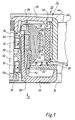
- Fig. 1 shows a greatly enlarged section through an external rotor motor 20.
- This has a hub 22 made of a suitable plastic, which is integrally formed with a bearing support tube 24, in which an upper ball bearing 26, a spacer 28 for the outer rings, and a lower ball bearing 30 are arranged, which ball bearings support the shaft 32 of an outer rotor 34.
- the inner rings of the ball bearings 26, 30 are braced against one another by a compression spring 36 which is arranged between the inner ring of the ball bearing 26 and a rotor part 38.
- the latter as shown, is attached to the upper end of the shaft 32 and carries a soft ferromagnetic ring 40 in which a rotor magnet 42 is arranged.
- a ring part 44 made of plastic extends around the ring 40 and is formed in one piece with five fan blades 46.
- a Hall IC 50 is arranged on a printed circuit board 52 opposite the lower end 48 of the rotor magnet 42, which carries electronic components for controlling the motor 20 and for error messages. The Hall IC 50 controls the current in the motor 20 and serves as an encoder for its speed.
- the shaft 32 has an annular groove 54 at the lower end, into which a holding part 56 engages resiliently, which is fixed by means of a spring 58 in the bearing support tube 24.
- An inner stator 60 is attached to the outside of the bearing support tube 24. This has a laminated core 62, in which by means of a coil carrier 64, 66 a winding 68 is attached. A connection 70 of the winding 68 is shown. It is soldered to a pin 72 fastened in the coil carrier 66.
- the hub 22 is formed in one piece with webs 74, which the hub 22 also connect a substantially cylindrical shell portion 76 which the Fan blades 46 surround radially at a distance, see. Fig. 2.
- the webs 74 form a Protective grille, which is shown in Fig. 2 and 7 and also as a handle for it serves to insert the motor 20 into a housing (FIGS. 3 to 5) or out of it exit.
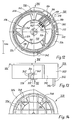
- FIG. 2 shows a plan view in the direction of arrow II of FIG. I. It can be seen that six webs 74 are fastened to the hub 22 and connect the hub 22 to the casing part 76.
- the hub 22, the webs 74 and the casing part 76 are designed as a one-piece plastic part. Approximately in the middle, the webs 74 are connected to one another by an annular web 80, on which an arrow 82 for the opening direction and an arrow 84 for the closing direction, as well as corresponding indicia (OPEN, CLOSE) are attached.
- connecting lines 86, 88 (+ and -) and 90 (Control line) soldered on and from there via a T-shaped clamping piece 92 the outside of the jacket part 76 and a further clamping piece 94, as well the outside of the jacket part 76, to a connector plug 96.
- a T-shaped clamping piece 92 the outside of the jacket part 76 and a further clamping piece 94, as well the outside of the jacket part 76, to a connector plug 96.
- the unit shown in Figs. 1 and 2 from external rotor motor 20, Fan blades 46 and casing tube 76 is designated 100. It represents one replaceable unit, which is complete as such in the event of a fault can be replaced without removing the fan housing must become.
- FIG. 4 shows a plan view of the open side of a fan housing 110.
- This has a protective grille 112 on its base, which is formed in one piece with the housing 110, and it has a substantially cylindrical recess 114 for receiving the cylindrical casing part 76 (FIG. 2).
- the outline shape of the housing 110 is essentially square, for example with the standard dimensions of 80 x 80 mm, but a thin-walled jacket part 116, in which the recess 114 is formed, projects beyond this square outline shape in some areas.
- recesses 118 A, 118 B, 118 C, 118 D are provided for receiving the pins 98 (FIG. 2).
- FIG. 3 shows the upper recess 118A in FIG. 4, which laterally merges into a latching recess 120A, which has a resilient latching tongue 122A on one side and a resilient latching tongue 124A on the other side.
- FIG. 5 shows recess 118B on the right in FIG. 4. This merges laterally into a latching recess 120B, which has a resilient latching tongue 122B on one side and a resilient latching tongue 124B on the other side.
- the remaining recesses 118C and 118D are identical to the recess 118B, and therefore identical reference numerals are used for them, but supplemented by the letters C and D.
- the cylindrical recess 114 has a radial Extension 126, which extends over an angle of approximately 20 °.
- the Coverage of this extension is designated 130 and shown in Fig. 3.
- locking members 132 for fastening the Connector 96 (Fig. 2).
- the housing 110 has holes 136 at its corners for permanent attachment this part of a component to be cooled, e.g. B. a transmitter, and it has two protruding pins 138 for a precise fixation.
- the housing 110 is permanently mounted on the part to be cooled.
- the Component 100 (FIG. 2) can then be installed in housing 100 used and removed from it if necessary, for. B. for a Repair.
- FIGS. 6 to 9 show the fan in its finished state and in approximately normal size.
- the component 100 is inserted into the housing 110 and locked there. This is done by axially inserting the pins 98 into the recesses 118A to 118D and then turning the component 100 clockwise by a few degrees in the direction of the arrow 84 (CLOSE).
- CLOSE direction of the arrow 84
- the pins 98 snap into the recesses 120A to 120D, as clearly shown in FIGS. 6, 8 and 9.
- the plug 96 is locked on the locking members 132, as shown in FIGS. 6 to 9.
- the component 100 is removed from the housing 102 in FIG reverse order, d. H. component 100 is in the direction of arrow 82 rotated counter-clockwise by a few degrees and then axially out of the housing 110 pulled out.
- the openings are between the radial ones Web 74 and the ring web 80 formed so that you can with your fingers in these openings can intervene and the protective grille can be used as a handle.
- the protective grille 112 shown in FIG one side of the finished fan and the protective grille 74, 80 shown in FIG. 2 is placed on the other side of the fan so that this on both Sides has a protective grille, both protective grids preferably made of plastic are trained.
- the protective grid 112 is integral with the housing 110 formed and the protective grid 74, 80 in one piece with the casing tube 76 and the hub 22.
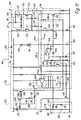
- the motor 20 is shown schematically on the right. This generated by a device 150, such as a tachometer generator, a signal n corresponding to the actual speed which is fed to a speed controller 152nd.
- the motor 20 is in series with an output stage 154 between the lines 86 (+) and 88 (ground).
- the output stage 154 is symbolically represented as an npn transistor. In Fig. 11, it is formed by the two transistors 224, 226.
- a control device 156 To control the Motor 20 serves a control device 156, which generally provides a Control signal for the motor 20 and for evaluating an error signal from Motor 20 is used.
- the control device 156 can be a control signal or a PWM signal provide a DC control signal.
- a DC voltage control signal is used, or a PWM signal 164, which is supplied from the control unit 156 to the motor 20 via the control line 90, where it is converted into a DC voltage on a line 159 via a filter 158 and the like
- Speed controller 152 is supplied as setpoint n target.
- the control can also take place via a DC voltage which is fed to the input 90 and can have values between 2 and 7 V, for example.
- connection 90 'from control unit 156 to control line 90 is interrupted, the speed controller 152 would constantly receive a signal that would correspond to a PWM signal 164 with the duty cycle 100%, and motor 20 would run at maximum speed.
- a switching element 160 is provided, which in this case blocks the output stage 154, so that the motor 20 receives no power and is switched off.
- a duty cycle of> 95% which is fed to the control line 90 and which is also interpreted as a shutdown signal.
- the connector When the fan is used in a motor vehicle, the connector becomes 86 connected to the positive pole of the vehicle battery (not shown).
- the Port 86 is connected to a filter 166 for EMI protection, and for Protection against incorrect connection to the battery is a diode 168 intended.
- a capacitor 170 is also provided, which also connects the motor 20 Reactive power supplied.
- An internal constant voltage source 172 connects one to a line 174 stabilized voltage of e.g. +7.7 V generated through a capacitor 176 is filtered.
- Hall IC 50 is connected to line 174 and is connected to the permanent magnetic rotor 42 (Fig. 1) is controlled and in turn depending on the position of this rotor via a connection 177 die Power stage 154 controls.
- a PTC resistor 180 In thermal connection with the motor 20 and the output stage 154 (or with the 11 transistors 224, 226 in FIG. 11) is a PTC resistor 180 provided, the output signal via a line 182 to the speed controller 152 is supplied and this regulates to zero speed when the Temperature of motor 20 / output stage 154 is a critical value for all components exceeds, e.g. 115 ° C.
- a measuring resistor 184 provided on which a voltage arises during operation, which is from the current i of the motor 20 is dependent and which is fed to a control element 186.
- control element If the voltage across resistor 184 becomes too high, the control element generates 186 at an output 188 a signal that blocks the output stage 154, e.g. during 13 seconds and it generates a signal at an output 190 which an npn transistor 192 is supplied and makes it conductive.
- the emitter of transistor 192 is connected to ground 88, its collector to the control line 90, i.e. if transistor 192 is conductive, the Control line 90 approximately the potential of ground 88.
- the line 90, 90 ' is connected via a resistor 194 to the Collector of an NPN transistor 196 connected, whose emitter is connected to ground 88 lies and the basis of which the PWM signal 164 is supplied during operation becomes.
- control line 90 When control line 90 is connected to ground 88 through transistor 192 it looks like PWM signal 164 has a duty cycle of 0%, and the engine 20 is turned off. The same applies if one of the entrances 90 supplied DC voltage control voltage assumes the value 0.
- the collector of transistor 196 is also connected via a resistor 198 a node 200, and this is via a resistor 202 and a capacitor 204 connected to ground 88 in parallel therewith connected.
- capacitor 204 charges through the pulses of the PWM signal 164, for which reference is made to FIG. 11. This creates on Node 200 has a positive potential different from zero. But will Transistor 192 conductive, because the motor current i is constantly too high, so it will Potential of node 200 is reduced, and you get one FAULT error signal.
- the PWM pulses 164 therefore go via the control line 90 Speed controller 152, and in the event of faults, because the transistor 192 is conductive an error signal in the opposite direction from the motor 20 to the control unit 156th
- the voltage across resistor 184 is also fed to a control element 208, that when it responds, the current i in the output stage 154 to one limited value.
- controller 186 deactivated, i.e. then only the starting current limit 208 is active.
- Line 188 is connected to the output of controller 152, the output of the Current limiter 208 and a diode element 209 connected. Generates the Regulator 152, control element 186, or current limiter 208 on its Output low potential, the diode member 209 is reduced conductive the voltage on line 177, thereby completely blocking the output stage 154 or partially, so that the motor 20 is either de-energized, or - when starting - The motor current i is limited.
- the target speed of the motor 20 is via a DC voltage (here: 2 ... 7 V) at input 90 or by the pulse duty factor pwm of PWM signal 164 specified. As long as this is less than 10%, the motor is 20. In the area the speed increases from 30 to 85%. With a duty cycle of over 95% the motor is switched off via the switching element 160, as already described.
- the motor current i is increased to one by the control element 208 predetermined maximum value limited by the Control signal for the output stage 154 is reduced accordingly if the Starting current i becomes too high.
- the periodic signal generated here by the control element 186 is transmitted via the Line 190 also feeds the NPN transistor 192 and causes this is switched on and off periodically. This also unlocks the potential at Point 90 changed periodically and via the control line 90 'to the control unit 156 transmitted where it generates the error signal FAULT already described.
- FIG. 11 shows a collectorless motor 20 with two stator winding phases 220, 222, which are each connected in series with a power transistor 224 or 226. These are controlled in the usual way for commutation via their bases by the Hall IC 50 (FIG. 10), which is not shown in FIG. 11.
- the base of transistor 224 is connected to the anode of a diode 228, that of transistor 226 to the anode of a diode 230.
- the cathodes of the diodes 228, 230 are connected to a line 232.
- Line 232 is connected to the collectors of two NPN transistors 234, 236, the emitters of which are connected to ground 88.
- transistors 234, 236 If one of the transistors 234, 236 is turned on, a connection is made from the base of transistors 224, 226 to ground, so this Transistors are blocked and the motor 20 no longer receives current. Becomes one of the transistors 234, 236 is only partially conductive, so it reduces the Base current of transistors 224, 226, so that the motor current i accordingly decreases. This happens when the current is limited, especially when the Motors 20
- the emitters of the transistors 224, 226 are via a node 240 and the Measuring resistor 184 connected to ground 88.
- the potential at the node 240 is supplied via a resistor 242 to the base of transistor 236, so that this acts as a current limiter, i.e. with increasing tension on Resistor 184, transistor 236 becomes increasingly conductive and limited thereby the motor current i, e.g. to a maximum value of about 0.5 A at the start.
- the output 252 of the OP amplifier 244 is connected through a capacitor 254 (e.g. 2.2 ⁇ F) with the positive input, via a resistor 256 (e.g. 100 kOhm) with node 246, through a resistor 258 to the base of the transistor 234, via a capacitor 260 (e.g. 1 nF) with ground 88 and via one Resistor 262 connected to the base of transistor 192.
- the basis of the Transistor 234 is also connected to ground 88 via a resistor 264.
- the op-amp 244 When the op-amp 244 has switched, it will remain by the action of the Capacitor 254 in this condition for about 13 seconds and then switches back to the state where its output is low, causing the Transistors 192 and 234 are blocked again and the motor 20 again Receives electricity. If it is still blocked, it will last for approx. 2 seconds switched on, and if it does not start, de-energized again for 13 seconds made.
- the PTC resistor becomes 180 high impedance, which reduces the potential at node 246 and thereby transistors 192 and 234 are also turned on and motor 20 is de-energized until the temperature at the PTC resistor 180 again has sunk far enough.
- the speed controller 152 works by comparing the signals n actual and n intended . For this he has an OP amplifier 152K, to which these signals are fed. If the speed of the motor 20 is too high, the output 270 of the OP amplifier 152K becomes high, and this signal is transmitted via a resistor 272 to the base of the transistor 236, makes it conductive, and thereby affects the transistors 224, 226, see that the motor current i and thus the speed of the motor 20 decrease.
- the control line 90 is connected to the line 174 and via a resistor 276 connected via a resistor 278 to a node 280, which via a capacitor 282 with ground 88 and a resistor 284 with the The minus input of the OP amplifier 152K is connected. This minus entrance is also connected to ground via a resistor 286.
- the control line 90 is through a resistor 290 with the base of a pnp transistor 292 connected, its emitter, as well as the emitter of a pnp transistor 294, on line 174.
- the collector of transistor 292 is grounded through a resistor 296 and connected to its base through a capacitor 298. That base is also through a resistor 300 to the collector of transistor 294 connected through a resistor 302 to the base of transistor 236 connected is.
- transistor 294 When transistor 294 is conductive, it introduces transistor 236 Base current and thereby turns off transistors 224, 226 so that the motor 20 is de-energized.
- the capacitor 282 is through the PWM pulses are constantly discharged sufficiently far that the transistor 292 is kept conductive by the potential on the control line 90 and consequently turns off transistor 294.
- the pulse duty factor of the PWM signal on the control line 90 exceeds the Value 95%, or the control line 90 '(Fig. 10) is interrupted, which in the Effect corresponds to a duty cycle of 100%, the capacitor 282 charged to a higher voltage by resistors 276, 278, 284, 286 is determined, and thereby the transistor 292 is blocked and the Transistor 294 becomes conductive and switches the motor in the manner described 20 from.
- control line 90 can be used in both directions
- Signals are transmitted, i.e. in the direction of the motor 20 signals (PWM signals 164 or a DC control voltage), which is the motor speed control, and in the reverse direction an error signal when the motor 20 to runs slowly or is prevented from rotating.
- FIGS. 12 to 15 show a second exemplary embodiment of a device fan 220 according to the invention, which is very small here and has an outer diameter of approximately 4 cm.
- a common reference scale of 1 cm is given by way of example in FIGS. 12 to 14 in order to illustrate typical size relationships.
- the device fan 320 is also here composed of two parts, namely an outer housing 322, the is provided on the outside with a flange 324 which is integral with a protective grille 326 is formed, and the a substantially cylindrical recess 328, into which the actual fan 330 is inserted and locked.
- the fan 330 has a hub 332, which has three webs 334 with one tubular outer part 336 is connected, the outer side 338 with sliding fit fits into the recess 328.
- the fan 330 has five fan blades 348, which are attached to an outer rotor 360 are.
- three lines 364, 366, 368 are provided here for electronics (not shown) outside of the fan part 330 because the electronics are such a small device fan would not have enough space in the fan 330 itself.
- 15 shows the lines 364, 366, 368 around two holding parts 370, 372 (on the outside of the tube 338) around a plug 374.
- One label is 376 designated.
- Outer housing 322 is also provided with a radial extension 380, the cover of which is designated 382. Their radial extension enables to rotate the fan part 330 in the outer housing 322 as far as that for Locking and unlocking is necessary.
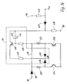
- FIG. 16 shows an embodiment for generating a signal corresponding to the actual speed n ist , cf. Fig. 10 and Fig. 11. Identical or equivalent parts are provided with the same reference numerals.
- the circuit 150 has an amplification element in the form of a pnp transistor 400 (preferably BC856B), the base of which is via a resistor 402 (preferably 1 k ⁇ ) is connected to the positive line 86, one Coupling device 404, 406 in the form of two diodes 404, 406 (preferably BAV70), the anodes of which correspond to that of the positive lead 86 connected side facing away from the stator winding phases 220, 222 are connected and their cathodes are connected to a point 408, a resistor 410 (preferably 39 k ⁇ ), which lies between the point 408 and the emitter of transistor 400, and a smoothing device in the form of a capacitor 414 (preferably 100 nF), which capacitor 414 is arranged between the base and the collector of transistor 400.
- the collector of transistor 400 is connected via a resistor 418 (preferably 36 k ⁇ ) connected to the ground line 88, at a point 412 between the Collector of transistor 400 and resistor 418 a speed dependent and voltage proportion
- the base of transistor 400 is connected to positive line 86 via resistor 402.
- phase 220 operates in generator mode, and the potential at point 408 is determined by the in FIG the stator winding phase 220 induced, the speed n is proportional voltage, which is added to the potential of the positive line 86, greater than the potential on the positive line 86.
- the transistor 400 operating as an amplification element becomes conductive, and a current flows through resistor 410, transistor 400 and Resistor 418 to ground line 88.
- This current is corresponding to that induced in the stator winding phase 220 Tension wavy.
- This ripple is caused by a AC negative feedback is eliminated by means of the capacitor 414, so that a direct current proportional to the rotor speed via the resistor 418 Ground line 88 flows. This gives the rotor speed at point 412 proportional potential.
- the potential at node 412 is 422 adds up the diode voltage of the diode 420 via the diode 420 and the resistor, and the result is n via the output of the operational amplifier 152 is supplied to see. Fig. 11.
- This circuit 150 functions independently of the level of the operating voltage 86 used and supplies a signal n ist that is proportional to the instantaneous speed of the motor 20.
Landscapes
- Engineering & Computer Science (AREA)
- Mechanical Engineering (AREA)
- General Engineering & Computer Science (AREA)
- Structures Of Non-Positive Displacement Pumps (AREA)
- Connection Of Motors, Electrical Generators, Mechanical Devices, And The Like (AREA)
- Control Of Motors That Do Not Use Commutators (AREA)
Applications Claiming Priority (4)
| Application Number | Priority Date | Filing Date | Title |
|---|---|---|---|
| DE20119155 | 2001-11-26 | ||
| DE20119155U | 2001-11-26 | ||
| DE20210846U | 2002-07-18 | ||
| DE20210846 | 2002-07-18 |
Publications (4)
| Publication Number | Publication Date |
|---|---|
| EP1314894A2 true EP1314894A2 (fr) | 2003-05-28 |
| EP1314894A3 EP1314894A3 (fr) | 2003-11-05 |
| EP1314894B1 EP1314894B1 (fr) | 2006-05-17 |
| EP1314894B2 EP1314894B2 (fr) | 2012-05-09 |
Family
ID=26057292
Family Applications (1)
| Application Number | Title | Priority Date | Filing Date |
|---|---|---|---|
| EP02023117A Expired - Lifetime EP1314894B2 (fr) | 2001-11-26 | 2002-10-15 | Ventilateur |
Country Status (4)
| Country | Link |
|---|---|
| US (2) | US6864653B2 (fr) |
| EP (1) | EP1314894B2 (fr) |
| AT (1) | ATE326635T1 (fr) |
| DE (2) | DE20215697U1 (fr) |
Cited By (4)
| Publication number | Priority date | Publication date | Assignee | Title |
|---|---|---|---|---|
| WO2005095802A1 (fr) * | 2004-03-16 | 2005-10-13 | Ebm-Papst St. Georgen Gmbh & Co. Kg | Ensemble comprenant un moteur a induit exterieur a commutation electronique |
| DE102009053620A1 (de) | 2009-11-17 | 2011-05-19 | Ziehl-Abegg Ag | Kommunikationsüberwachung für einen Außenläufermotor |
| CN106368865A (zh) * | 2015-07-20 | 2017-02-01 | 德尔福技术有限公司 | 流体泵 |
| US9994085B2 (en) | 2007-11-23 | 2018-06-12 | Spal Automotive S.R.L | Ventilating unit, especially for motor vehicles |
Families Citing this family (31)
| Publication number | Priority date | Publication date | Assignee | Title |
|---|---|---|---|---|
| WO2002019511A1 (fr) * | 2000-08-30 | 2002-03-07 | Papst-Motoren Gmbh & Co. Kg | Systeme de ventilation |
| US6924979B2 (en) * | 2001-07-30 | 2005-08-02 | Hewlett-Packard Development Company, L.P. | Mounting apparatus for coupling control circuitry to an air moving device |
| DE10310830A1 (de) | 2003-03-13 | 2004-09-23 | Robert Bosch Gmbh | Verfahren und Steuereinheit zur Ansteuerung von Lüftermotoren |
| JP2005303015A (ja) * | 2004-04-12 | 2005-10-27 | Nippon Densan Corp | ヒートシンクファン |
| EP1601095B1 (fr) * | 2004-05-12 | 2007-08-29 | ebm-papst St. Georgen GmbH & Co. KG | Moteur à commutation électronique à double impulsion et procédé pour le démarrage d'un tel moteur |
| JP4702017B2 (ja) * | 2005-12-02 | 2011-06-15 | 株式会社デンソー | 車載空調装置の送風機用モータ駆動装置 |
| US7602157B2 (en) | 2005-12-28 | 2009-10-13 | Flyback Energy, Inc. | Supply architecture for inductive loads |
| TWI340534B (en) * | 2006-10-25 | 2011-04-11 | Sunonwealth Electr Mach Ind Co | Pwm motor drive circuit |
| US20080247689A1 (en) * | 2007-04-06 | 2008-10-09 | Nidec Corporation | Motor |
| US20080286093A1 (en) * | 2007-05-16 | 2008-11-20 | Bauer Jr Thomas | Cooler Fan Hub |
| JP4946625B2 (ja) * | 2007-05-21 | 2012-06-06 | 日本電産株式会社 | モータ |
| US8398378B2 (en) * | 2007-07-24 | 2013-03-19 | Brose Fahrzeugteile GmbH & Co. Kommanditgesellschaft, Würzburg | Tangential drive module assembly and method of assembly for airflow induction |
| CN101919150B (zh) * | 2007-09-18 | 2013-12-18 | 菲莱贝克能源公司 | 从局部能源产生具有低谐波畸变的交流功率的电流波形结构 |
| US8672649B2 (en) * | 2007-10-10 | 2014-03-18 | Delta T Corporation | Ceiling fan system with brushless motor |
| WO2009055663A1 (fr) * | 2007-10-26 | 2009-04-30 | The Bergquist-Torrington Company | Appareil et procédé pour obtenir et isoler un ventilateur modulaire et des sous-ensembles de moteur dans des systèmes de déplacement d'air |
| CN101714812A (zh) * | 2008-10-08 | 2010-05-26 | 鸿富锦精密工业(深圳)有限公司 | 风扇控制电路 |
| TWI467914B (zh) * | 2008-10-17 | 2015-01-01 | Hon Hai Prec Ind Co Ltd | 風扇控制電路 |
| TW201020400A (en) * | 2008-11-27 | 2010-06-01 | Compal Electronics Inc | Fan module for electronic device |
| US8860273B2 (en) * | 2009-12-28 | 2014-10-14 | Flyback Energy, Inc. | External field interaction motor |
| CA2785715A1 (fr) * | 2009-12-28 | 2011-07-28 | Paul M. Babcock | Alimentation electrique universelle pouvant etre regulee, avec gestion de puissance reactive |
| US8610387B2 (en) * | 2010-04-30 | 2013-12-17 | Sunonwealth Electric Machine Industry Co., Ltd. | Motor system |
| USD701954S1 (en) | 2012-06-14 | 2014-04-01 | Ebm-Papst St. Georgen Gmbh & Co. Kg | Fan housing |
| JP6281250B2 (ja) * | 2013-11-11 | 2018-02-21 | 日本電産株式会社 | モータ |
| DE102013017975A1 (de) * | 2013-11-29 | 2015-06-03 | Fte Automotive Gmbh | Elektromotorisch angetriebene Flüssigkeitspumpe, insbesondere zur Zwangsschmierung eines Schaltgetriebes für Kraftfahrzeuge |
| JP6330219B2 (ja) * | 2014-03-17 | 2018-05-30 | 株式会社デンソー | モータ制御装置 |
| DE102014206277A1 (de) | 2014-04-02 | 2015-10-08 | BSH Hausgeräte GmbH | Hausgerätevorrichtung |
| DE202015106847U1 (de) | 2015-12-16 | 2017-03-17 | Elektrosil Systeme Der Elektronik Gmbh | Lüfter mit Statussignalgenerierung und Übermittlung des Statussignals über eine Versorgungsleitung |
| JP2018178802A (ja) * | 2017-04-07 | 2018-11-15 | 日本電産株式会社 | ファンモータ |
| DE102017111826A1 (de) * | 2017-05-30 | 2018-12-06 | Ebm-Papst Mulfingen Gmbh & Co. Kg | Vorrichtung zur Reduzierung von schädlichen Lagerspannungen |
| TWM550341U (zh) * | 2017-07-24 | 2017-10-11 | Dongguan City Hanshuo Plastic Co Ltd | 快拆式無導線之散熱風扇結構 |
| USD1028204S1 (en) | 2023-12-13 | 2024-05-21 | Danming YANG | Fan with light |
Family Cites Families (36)
| Publication number | Priority date | Publication date | Assignee | Title |
|---|---|---|---|---|
| CH654455A5 (de) * | 1980-05-10 | 1986-02-14 | Papst Motoren Gmbh & Co Kg | Buerstenlose gleichstrommotoranordnung, insbesondere fuer magnetplattenantriebe. |
| DE3404466A1 (de) | 1984-02-08 | 1985-08-08 | Ebm Elektrobau Mulfingen Gmbh & Co, 7119 Mulfingen | Aussenlaeufermotor |
| US4554491A (en) * | 1984-08-10 | 1985-11-19 | Msl Industries, Inc. | Brushless DC motor having a laminated stator with a single stator winding |
| DE3542214A1 (de) | 1984-12-03 | 1986-06-05 | Papst-Motoren GmbH & Co KG, 7742 St Georgen | Ventilator |
| DE3546683C3 (de) | 1985-02-22 | 2003-10-09 | Bosch Gmbh Robert | Verfahren zum Betreiben einer Datenverarbeitungsanlage |
| DE3820857C2 (de) | 1988-06-04 | 1993-12-02 | Licentia Gmbh | Elektromotor mit einem Außenläufer und einem mit diesem verbundenem Lüfterrad |
| US4949022A (en) * | 1989-01-27 | 1990-08-14 | Lipman Leonard H | Solid state DC fan motor |
| DE4033092A1 (de) † | 1990-10-18 | 1992-04-23 | Telefunken Electronic Gmbh | Lueftervorrichtung fuer kraftfahrzeuge |
| US5099181A (en) * | 1991-05-03 | 1992-03-24 | Canon K N Hsu | Pulse-width modulation speed controllable DC brushless cooling fan |
| US5208730A (en) * | 1991-06-27 | 1993-05-04 | Compaq Computer Corporation | Computer cooling fan vibration isolation apparatus |
| DE4127134B4 (de) | 1991-08-15 | 2004-07-08 | Papst Licensing Gmbh & Co. Kg | Diagonallüfter |
| DE4141106C2 (de) | 1991-12-13 | 2001-10-04 | Papst Licensing Gmbh & Co Kg | Radialgebläse |
| DE4225534A1 (de) † | 1992-08-01 | 1994-02-03 | Rolf Gnauert | Anordnung zum Betreiben, Steuern und Überwachen von Elektromotoren in untertägigen Betrieben |
| US5845045A (en) | 1993-11-28 | 1998-12-01 | Papst-Motoren Gmbh & Co. Kg | Method and apparatus for DC motor speed control |
| KR0135898B1 (ko) * | 1995-02-24 | 1998-06-15 | 김광호 | 냉각팬 동작 상태 판단장치 |
| US5638895A (en) * | 1996-03-25 | 1997-06-17 | Dodson; Douglas A. | Twin fan cooling device |
| DE19628698C1 (de) | 1996-07-17 | 1997-10-09 | Daimler Benz Ag | Fahrzeugsitz |
| FR2753848B1 (fr) † | 1996-09-26 | 1998-12-11 | Moteur electrique a commande electronique integree | |
| DE19703516C1 (de) | 1997-01-31 | 1998-05-07 | Daimler Benz Ag | Fahrzeugsitz |
| US6695046B1 (en) * | 1997-02-18 | 2004-02-24 | Hoffman Controls Corp. | Variable speed fan motor control for forced air heating/cooling system |
| TW338585U (en) | 1997-07-15 | 1998-08-11 | Asia Vital Components Co Ltd | Improvement on a non-carbon brush DC fan |
| GB9717242D0 (en) | 1997-08-15 | 1997-10-22 | Minebea Electronics Uk Ltd | Circuit |
| US5947691A (en) * | 1997-10-29 | 1999-09-07 | Comair Rotron, Inc. | Winding supply circuit with current and thermal protective elements |
| DE19826458A1 (de) * | 1998-06-13 | 1999-12-16 | Papst Motoren Gmbh & Co Kg | Anordnung mit einem Elektromotor |
| US6075698A (en) * | 1998-10-27 | 2000-06-13 | Ads, The Power Resource, Inc. | Removable fan for rack mounted rectifiers |
| DE29819962U1 (de) | 1998-11-09 | 2000-03-23 | ebm Werke GmbH & Co., 74673 Mulfingen | Radialgebläse mit Anschluß-Steckverbindung |
| US5977733A (en) | 1998-12-08 | 1999-11-02 | Shin Jiuh Corporation | Fan control device with breakdown warning capability |
| US6147465A (en) * | 1999-03-25 | 2000-11-14 | General Electric Company | Microprocessor controlled single phase motor with external rotor having integral fan |
| US6183221B1 (en) | 1999-10-29 | 2001-02-06 | Hsieh Hsin-Mao | Heat dissipation fan with a shaft positioned to prevent chafing between the fan blades and the bearing |
| DE10009128C1 (de) | 2000-02-26 | 2001-08-16 | Wet Automotive Systems Ag | Einrichtung zur Belüftung eines Fahrzeugsitzes |
| US6528987B1 (en) * | 2000-06-19 | 2003-03-04 | Analog Devices, Inc. | Method and apparatus for determining fan speed |
| US6262549B1 (en) | 2000-06-29 | 2001-07-17 | System General Corp. | Fan speed pulse filter for a PWM fan |
| US6747424B1 (en) * | 2000-10-02 | 2004-06-08 | International Business Machines Corporation | Integrated fan speed control and fault detection circuitry |
| US6517318B2 (en) | 2000-12-11 | 2003-02-11 | Hsieh Hsin-Mao | Buffer pad for use in an electric fan |
| US6690576B2 (en) * | 2001-07-31 | 2004-02-10 | Hewlett Packard Development Company, L.P. | Externally mounted on-line replaceable fan module |
| US6376946B1 (en) * | 2001-08-23 | 2002-04-23 | Bill Lee | D.C. brushless air fan with an annular oil trough |
-
2002
- 2002-09-30 US US10/262,400 patent/US6864653B2/en not_active Expired - Fee Related
- 2002-10-12 DE DE20215697U patent/DE20215697U1/de not_active Expired - Lifetime
- 2002-10-15 EP EP02023117A patent/EP1314894B2/fr not_active Expired - Lifetime
- 2002-10-15 AT AT02023117T patent/ATE326635T1/de not_active IP Right Cessation
- 2002-10-15 DE DE50206794T patent/DE50206794D1/de not_active Expired - Lifetime
-
2004
- 2004-11-05 US US10/982,307 patent/US7352094B2/en not_active Expired - Fee Related
Cited By (4)
| Publication number | Priority date | Publication date | Assignee | Title |
|---|---|---|---|---|
| WO2005095802A1 (fr) * | 2004-03-16 | 2005-10-13 | Ebm-Papst St. Georgen Gmbh & Co. Kg | Ensemble comprenant un moteur a induit exterieur a commutation electronique |
| US9994085B2 (en) | 2007-11-23 | 2018-06-12 | Spal Automotive S.R.L | Ventilating unit, especially for motor vehicles |
| DE102009053620A1 (de) | 2009-11-17 | 2011-05-19 | Ziehl-Abegg Ag | Kommunikationsüberwachung für einen Außenläufermotor |
| CN106368865A (zh) * | 2015-07-20 | 2017-02-01 | 德尔福技术有限公司 | 流体泵 |
Also Published As
| Publication number | Publication date |
|---|---|
| EP1314894B1 (fr) | 2006-05-17 |
| US20050077792A1 (en) | 2005-04-14 |
| US6864653B2 (en) | 2005-03-08 |
| ATE326635T1 (de) | 2006-06-15 |
| US7352094B2 (en) | 2008-04-01 |
| US20030099561A1 (en) | 2003-05-29 |
| DE50206794D1 (de) | 2006-06-22 |
| EP1314894A3 (fr) | 2003-11-05 |
| EP1314894B2 (fr) | 2012-05-09 |
| DE20215697U1 (de) | 2003-01-02 |
Similar Documents
| Publication | Publication Date | Title |
|---|---|---|
| EP1314894A2 (fr) | Ventilateur | |
| EP0744807B1 (fr) | Procédé de limitation du courant d'un moteur à courant continu, et moteur à courant continu pour mettre en oeuvre un tel procédé | |
| EP0766370B1 (fr) | Moteur à rotor extérieur commuté électroniquement | |
| DE3022836C1 (de) | Kollektorloser Gleichstrommotor | |
| DE2804561C2 (fr) | ||
| EP1908162B1 (fr) | Moteur electrique sans balai | |
| EP1104950B1 (fr) | Moteur à courant continu commuté électroniquement | |
| DE60219851T2 (de) | Verfahren zur Strombegrenzung eines Gleichstrommotors | |
| EP1748545B1 (fr) | Moteur à commutation électronique et procédé de contrôle du moteur à commutation électronique | |
| CH658348A5 (de) | Zweipulsiger kollektorloser gleichstrommotor. | |
| WO2000028646A2 (fr) | Moteur a commutation electronique | |
| EP0887914A1 (fr) | Méthode pour influencer la commutation pour moteur à courant continu sans collecteur et moteur pour la mise en oeuvre d'une telle méthode | |
| DE112007003276T5 (de) | Bürstenlose Motoreinheit | |
| WO2006077069A1 (fr) | Commutation de commande pour moteur a commutation electronique | |
| DE2807833A1 (de) | Buerstenloses tachometer | |
| EP0986855B1 (fr) | Moteur a commutation electrique | |
| DE2822315A1 (de) | Kollektorloser gleichstrommotor | |
| DE20019449U1 (de) | Elektronisch kommutierter Gleichstrommotor | |
| EP1107441A2 (fr) | Moteur à courant continu à communication électronique | |
| EP2278339A1 (fr) | Moteur sans collecteur monophasé | |
| DE19518991A1 (de) | Verfahren zum Betrieb eines elektronisch kommutierten Motors, und Motor zur Durchführung eines solchen Verfahrens | |
| DE3044027C2 (de) | Stromregler für einen Gleichstrommotor | |
| DE3203829C2 (de) | Antriebsschaltung für einen kollektorlosen Gleichstrommotor mit Permanentmagnetrotor | |
| DE2339260C2 (de) | Kollektorloser Gleichstrommotor | |
| DE19939861A1 (de) | Motor-Laststeuersystem |
Legal Events
| Date | Code | Title | Description |
|---|---|---|---|
| PUAI | Public reference made under article 153(3) epc to a published international application that has entered the european phase |
Free format text: ORIGINAL CODE: 0009012 |
|
| 17P | Request for examination filed |
Effective date: 20021015 |
|
| AK | Designated contracting states |
Designated state(s): AT BE BG CH CY CZ DE DK EE ES FI FR GB GR IE IT LI LU MC NL PT SE SK TR |
|
| AX | Request for extension of the european patent |
Extension state: AL LT LV MK RO SI |
|
| PUAL | Search report despatched |
Free format text: ORIGINAL CODE: 0009013 |
|
| AK | Designated contracting states |
Kind code of ref document: A3 Designated state(s): AT BE BG CH CY CZ DE DK EE ES FI FR GB GR IE IT LI LU MC NL PT SE SK TR |
|
| AX | Request for extension of the european patent |
Extension state: AL LT LV MK RO SI |
|
| 17Q | First examination report despatched |
Effective date: 20031209 |
|
| AKX | Designation fees paid |
Designated state(s): AT BE BG CH CY CZ DE DK EE ES FI FR GB GR IE IT LI LU MC NL PT SE SK TR |
|
| GRAP | Despatch of communication of intention to grant a patent |
Free format text: ORIGINAL CODE: EPIDOSNIGR1 |
|
| RAP1 | Party data changed (applicant data changed or rights of an application transferred) |
Owner name: EBM-PAPST ST. GEORGEN GMBH & CO. KG |
|
| GRAS | Grant fee paid |
Free format text: ORIGINAL CODE: EPIDOSNIGR3 |
|
| GRAA | (expected) grant |
Free format text: ORIGINAL CODE: 0009210 |
|
| RIN1 | Information on inventor provided before grant (corrected) |
Inventor name: WINKLER, WOLFGANG ARNO Inventor name: VON DER HEYDT, THOMAS |
|
| AK | Designated contracting states |
Kind code of ref document: B1 Designated state(s): AT BE BG CH CY CZ DE DK EE ES FI FR GB GR IE IT LI LU MC NL PT SE SK TR |
|
| PG25 | Lapsed in a contracting state [announced via postgrant information from national office to epo] |
Ref country code: IT Free format text: LAPSE BECAUSE OF FAILURE TO SUBMIT A TRANSLATION OF THE DESCRIPTION OR TO PAY THE FEE WITHIN THE PRESCRIBED TIME-LIMIT;WARNING: LAPSES OF ITALIAN PATENTS WITH EFFECTIVE DATE BEFORE 2007 MAY HAVE OCCURRED AT ANY TIME BEFORE 2007. THE CORRECT EFFECTIVE DATE MAY BE DIFFERENT FROM THE ONE RECORDED. Effective date: 20060517 Ref country code: IE Free format text: LAPSE BECAUSE OF FAILURE TO SUBMIT A TRANSLATION OF THE DESCRIPTION OR TO PAY THE FEE WITHIN THE PRESCRIBED TIME-LIMIT Effective date: 20060517 Ref country code: SK Free format text: LAPSE BECAUSE OF FAILURE TO SUBMIT A TRANSLATION OF THE DESCRIPTION OR TO PAY THE FEE WITHIN THE PRESCRIBED TIME-LIMIT Effective date: 20060517 Ref country code: CZ Free format text: LAPSE BECAUSE OF FAILURE TO SUBMIT A TRANSLATION OF THE DESCRIPTION OR TO PAY THE FEE WITHIN THE PRESCRIBED TIME-LIMIT Effective date: 20060517 Ref country code: FI Free format text: LAPSE BECAUSE OF FAILURE TO SUBMIT A TRANSLATION OF THE DESCRIPTION OR TO PAY THE FEE WITHIN THE PRESCRIBED TIME-LIMIT Effective date: 20060517 Ref country code: NL Free format text: LAPSE BECAUSE OF FAILURE TO SUBMIT A TRANSLATION OF THE DESCRIPTION OR TO PAY THE FEE WITHIN THE PRESCRIBED TIME-LIMIT Effective date: 20060517 |
|
| REG | Reference to a national code |
Ref country code: GB Ref legal event code: FG4D Free format text: NOT ENGLISH |
|
| REG | Reference to a national code |
Ref country code: CH Ref legal event code: EP |
|
| REG | Reference to a national code |
Ref country code: IE Ref legal event code: FG4D Free format text: LANGUAGE OF EP DOCUMENT: GERMAN |
|
| REF | Corresponds to: |
Ref document number: 50206794 Country of ref document: DE Date of ref document: 20060622 Kind code of ref document: P |
|
| GBT | Gb: translation of ep patent filed (gb section 77(6)(a)/1977) |
Effective date: 20060621 |
|
| REG | Reference to a national code |
Ref country code: SE Ref legal event code: TRGR |
|
| PG25 | Lapsed in a contracting state [announced via postgrant information from national office to epo] |
Ref country code: DK Free format text: LAPSE BECAUSE OF FAILURE TO SUBMIT A TRANSLATION OF THE DESCRIPTION OR TO PAY THE FEE WITHIN THE PRESCRIBED TIME-LIMIT Effective date: 20060817 |
|
| PG25 | Lapsed in a contracting state [announced via postgrant information from national office to epo] |
Ref country code: ES Free format text: LAPSE BECAUSE OF FAILURE TO SUBMIT A TRANSLATION OF THE DESCRIPTION OR TO PAY THE FEE WITHIN THE PRESCRIBED TIME-LIMIT Effective date: 20060828 |
|
| PG25 | Lapsed in a contracting state [announced via postgrant information from national office to epo] |
Ref country code: PT Free format text: LAPSE BECAUSE OF FAILURE TO SUBMIT A TRANSLATION OF THE DESCRIPTION OR TO PAY THE FEE WITHIN THE PRESCRIBED TIME-LIMIT Effective date: 20061017 |
|
| PG25 | Lapsed in a contracting state [announced via postgrant information from national office to epo] |
Ref country code: CH Free format text: LAPSE BECAUSE OF NON-PAYMENT OF DUE FEES Effective date: 20061031 Ref country code: MC Free format text: LAPSE BECAUSE OF NON-PAYMENT OF DUE FEES Effective date: 20061031 Ref country code: LI Free format text: LAPSE BECAUSE OF NON-PAYMENT OF DUE FEES Effective date: 20061031 |
|
| NLV1 | Nl: lapsed or annulled due to failure to fulfill the requirements of art. 29p and 29m of the patents act | ||
| REG | Reference to a national code |
Ref country code: IE Ref legal event code: FD4D |
|
| ET | Fr: translation filed | ||
| PLBI | Opposition filed |
Free format text: ORIGINAL CODE: 0009260 |
|
| PLAX | Notice of opposition and request to file observation + time limit sent |
Free format text: ORIGINAL CODE: EPIDOSNOBS2 |
|
| 26 | Opposition filed |
Opponent name: HKR CLIMATEC GMBH Effective date: 20070216 Opponent name: MEYER, THORSTEN, DIPL.-PHYS. Effective date: 20070219 |
|
| REG | Reference to a national code |
Ref country code: CH Ref legal event code: PL |
|
| PLAF | Information modified related to communication of a notice of opposition and request to file observations + time limit |
Free format text: ORIGINAL CODE: EPIDOSCOBS2 |
|
| PLBB | Reply of patent proprietor to notice(s) of opposition received |
Free format text: ORIGINAL CODE: EPIDOSNOBS3 |
|
| BERE | Be: lapsed |
Owner name: EBM-PAPST ST. GEORGEN G.M.B.H. & CO. KG Effective date: 20061031 |
|
| PG25 | Lapsed in a contracting state [announced via postgrant information from national office to epo] |
Ref country code: AT Free format text: LAPSE BECAUSE OF NON-PAYMENT OF DUE FEES Effective date: 20061015 |
|
| PG25 | Lapsed in a contracting state [announced via postgrant information from national office to epo] |
Ref country code: GR Free format text: LAPSE BECAUSE OF FAILURE TO SUBMIT A TRANSLATION OF THE DESCRIPTION OR TO PAY THE FEE WITHIN THE PRESCRIBED TIME-LIMIT Effective date: 20060818 |
|
| PG25 | Lapsed in a contracting state [announced via postgrant information from national office to epo] |
Ref country code: EE Free format text: LAPSE BECAUSE OF FAILURE TO SUBMIT A TRANSLATION OF THE DESCRIPTION OR TO PAY THE FEE WITHIN THE PRESCRIBED TIME-LIMIT Effective date: 20060517 Ref country code: BG Free format text: LAPSE BECAUSE OF FAILURE TO SUBMIT A TRANSLATION OF THE DESCRIPTION OR TO PAY THE FEE WITHIN THE PRESCRIBED TIME-LIMIT Effective date: 20060817 |
|
| PG25 | Lapsed in a contracting state [announced via postgrant information from national office to epo] |
Ref country code: LU Free format text: LAPSE BECAUSE OF NON-PAYMENT OF DUE FEES Effective date: 20061015 Ref country code: TR Free format text: LAPSE BECAUSE OF FAILURE TO SUBMIT A TRANSLATION OF THE DESCRIPTION OR TO PAY THE FEE WITHIN THE PRESCRIBED TIME-LIMIT Effective date: 20060517 |
|
| PG25 | Lapsed in a contracting state [announced via postgrant information from national office to epo] |
Ref country code: CY Free format text: LAPSE BECAUSE OF FAILURE TO SUBMIT A TRANSLATION OF THE DESCRIPTION OR TO PAY THE FEE WITHIN THE PRESCRIBED TIME-LIMIT Effective date: 20060517 |
|
| RDAF | Communication despatched that patent is revoked |
Free format text: ORIGINAL CODE: EPIDOSNREV1 |
|
| APBM | Appeal reference recorded |
Free format text: ORIGINAL CODE: EPIDOSNREFNO |
|
| APBP | Date of receipt of notice of appeal recorded |
Free format text: ORIGINAL CODE: EPIDOSNNOA2O |
|
| APAH | Appeal reference modified |
Free format text: ORIGINAL CODE: EPIDOSCREFNO |
|
| APBQ | Date of receipt of statement of grounds of appeal recorded |
Free format text: ORIGINAL CODE: EPIDOSNNOA3O |
|
| PG25 | Lapsed in a contracting state [announced via postgrant information from national office to epo] |
Ref country code: BE Free format text: LAPSE BECAUSE OF FAILURE TO SUBMIT A TRANSLATION OF THE DESCRIPTION OR TO PAY THE FEE WITHIN THE PRESCRIBED TIME-LIMIT Effective date: 20061031 |
|
| APBU | Appeal procedure closed |
Free format text: ORIGINAL CODE: EPIDOSNNOA9O |
|
| RIC2 | Information provided on ipc code assigned after grant |
Ipc: F04D 25/06 20060101AFI20111221BHEP Ipc: H02P 7/00 20060101ALI20111221BHEP Ipc: H02H 7/08 20060101ALI20111221BHEP Ipc: F04D 27/02 20060101ALI20111221BHEP Ipc: H02H 7/093 20060101ALI20111221BHEP |
|
| PUAH | Patent maintained in amended form |
Free format text: ORIGINAL CODE: 0009272 |
|
| STAA | Information on the status of an ep patent application or granted ep patent |
Free format text: STATUS: PATENT MAINTAINED AS AMENDED |
|
| 27A | Patent maintained in amended form |
Effective date: 20120509 |
|
| AK | Designated contracting states |
Kind code of ref document: B2 Designated state(s): AT BE BG CH CY CZ DE DK EE ES FI FR GB GR IE IT LI LU MC NL PT SE SK TR |
|
| REG | Reference to a national code |
Ref country code: SE Ref legal event code: RPEO |
|
| REG | Reference to a national code |
Ref country code: DE Ref legal event code: R102 Ref document number: 50206794 Country of ref document: DE Effective date: 20120509 |
|
| REG | Reference to a national code |
Ref country code: FR Ref legal event code: PLFP Year of fee payment: 15 |
|
| PGFP | Annual fee paid to national office [announced via postgrant information from national office to epo] |
Ref country code: IT Payment date: 20160830 Year of fee payment: 15 |
|
| PGFP | Annual fee paid to national office [announced via postgrant information from national office to epo] |
Ref country code: FR Payment date: 20160919 Year of fee payment: 15 |
|
| PGFP | Annual fee paid to national office [announced via postgrant information from national office to epo] |
Ref country code: DE Payment date: 20161004 Year of fee payment: 15 Ref country code: GB Payment date: 20161026 Year of fee payment: 15 |
|
| PGFP | Annual fee paid to national office [announced via postgrant information from national office to epo] |
Ref country code: SE Payment date: 20161024 Year of fee payment: 15 |
|
| REG | Reference to a national code |
Ref country code: DE Ref legal event code: R119 Ref document number: 50206794 Country of ref document: DE |
|
| REG | Reference to a national code |
Ref country code: SE Ref legal event code: EUG |
|
| GBPC | Gb: european patent ceased through non-payment of renewal fee |
Effective date: 20171015 |
|
| REG | Reference to a national code |
Ref country code: FR Ref legal event code: ST Effective date: 20180629 |
|
| PG25 | Lapsed in a contracting state [announced via postgrant information from national office to epo] |
Ref country code: GB Free format text: LAPSE BECAUSE OF NON-PAYMENT OF DUE FEES Effective date: 20171015 Ref country code: DE Free format text: LAPSE BECAUSE OF NON-PAYMENT OF DUE FEES Effective date: 20180501 |
|
| PG25 | Lapsed in a contracting state [announced via postgrant information from national office to epo] |
Ref country code: SE Free format text: LAPSE BECAUSE OF NON-PAYMENT OF DUE FEES Effective date: 20171016 Ref country code: FR Free format text: LAPSE BECAUSE OF NON-PAYMENT OF DUE FEES Effective date: 20171031 |
|
| PG25 | Lapsed in a contracting state [announced via postgrant information from national office to epo] |
Ref country code: IT Free format text: LAPSE BECAUSE OF NON-PAYMENT OF DUE FEES Effective date: 20171015 |