EP1314896A2 - Behälter mit Belüftungseinrichtung - Google Patents
Behälter mit Belüftungseinrichtung Download PDFInfo
- Publication number
- EP1314896A2 EP1314896A2 EP02020392A EP02020392A EP1314896A2 EP 1314896 A2 EP1314896 A2 EP 1314896A2 EP 02020392 A EP02020392 A EP 02020392A EP 02020392 A EP02020392 A EP 02020392A EP 1314896 A2 EP1314896 A2 EP 1314896A2
- Authority
- EP
- European Patent Office
- Prior art keywords
- tank
- vent hole
- boss
- reservoir
- valve
- Prior art date
- Legal status (The legal status is an assumption and is not a legal conclusion. Google has not performed a legal analysis and makes no representation as to the accuracy of the status listed.)
- Withdrawn
Links
Images


Classifications
-
- F—MECHANICAL ENGINEERING; LIGHTING; HEATING; WEAPONS; BLASTING
- F15—FLUID-PRESSURE ACTUATORS; HYDRAULICS OR PNEUMATICS IN GENERAL
- F15B—SYSTEMS ACTING BY MEANS OF FLUIDS IN GENERAL; FLUID-PRESSURE ACTUATORS, e.g. SERVOMOTORS; DETAILS OF FLUID-PRESSURE SYSTEMS, NOT OTHERWISE PROVIDED FOR
- F15B1/00—Installations or systems with accumulators; Supply reservoir or sump assemblies
- F15B1/26—Supply reservoir or sump assemblies
-
- B—PERFORMING OPERATIONS; TRANSPORTING
- B60—VEHICLES IN GENERAL
- B60T—VEHICLE BRAKE CONTROL SYSTEMS OR PARTS THEREOF; BRAKE CONTROL SYSTEMS OR PARTS THEREOF, IN GENERAL; ARRANGEMENT OF BRAKING ELEMENTS ON VEHICLES IN GENERAL; PORTABLE DEVICES FOR PREVENTING UNWANTED MOVEMENT OF VEHICLES; VEHICLE MODIFICATIONS TO FACILITATE COOLING OF BRAKES
- B60T11/00—Transmitting braking action from initiating means to ultimate brake actuator without power assistance or drive or where such assistance or drive is irrelevant
- B60T11/10—Transmitting braking action from initiating means to ultimate brake actuator without power assistance or drive or where such assistance or drive is irrelevant transmitting by fluid means, e.g. hydraulic
- B60T11/16—Master control, e.g. master cylinders
- B60T11/22—Master control, e.g. master cylinders characterised by being integral with reservoir
-
- B—PERFORMING OPERATIONS; TRANSPORTING
- B60—VEHICLES IN GENERAL
- B60T—VEHICLE BRAKE CONTROL SYSTEMS OR PARTS THEREOF; BRAKE CONTROL SYSTEMS OR PARTS THEREOF, IN GENERAL; ARRANGEMENT OF BRAKING ELEMENTS ON VEHICLES IN GENERAL; PORTABLE DEVICES FOR PREVENTING UNWANTED MOVEMENT OF VEHICLES; VEHICLE MODIFICATIONS TO FACILITATE COOLING OF BRAKES
- B60T11/00—Transmitting braking action from initiating means to ultimate brake actuator without power assistance or drive or where such assistance or drive is irrelevant
- B60T11/10—Transmitting braking action from initiating means to ultimate brake actuator without power assistance or drive or where such assistance or drive is irrelevant transmitting by fluid means, e.g. hydraulic
- B60T11/26—Reservoirs
-
- B—PERFORMING OPERATIONS; TRANSPORTING
- B60—VEHICLES IN GENERAL
- B60T—VEHICLE BRAKE CONTROL SYSTEMS OR PARTS THEREOF; BRAKE CONTROL SYSTEMS OR PARTS THEREOF, IN GENERAL; ARRANGEMENT OF BRAKING ELEMENTS ON VEHICLES IN GENERAL; PORTABLE DEVICES FOR PREVENTING UNWANTED MOVEMENT OF VEHICLES; VEHICLE MODIFICATIONS TO FACILITATE COOLING OF BRAKES
- B60T17/00—Component parts, details, or accessories of power brake systems not covered by groups B60T8/00, B60T13/00 or B60T15/00, or presenting other characteristic features
- B60T17/06—Applications or arrangements of reservoirs
-
- B—PERFORMING OPERATIONS; TRANSPORTING
- B62—LAND VEHICLES FOR TRAVELLING OTHERWISE THAN ON RAILS
- B62D—MOTOR VEHICLES; TRAILERS
- B62D5/00—Power-assisted or power-driven steering
- B62D5/06—Power-assisted or power-driven steering fluid, i.e. using a pressurised fluid for most or all the force required for steering a vehicle
- B62D5/062—Details, component parts
-
- F—MECHANICAL ENGINEERING; LIGHTING; HEATING; WEAPONS; BLASTING
- F16—ENGINEERING ELEMENTS AND UNITS; GENERAL MEASURES FOR PRODUCING AND MAINTAINING EFFECTIVE FUNCTIONING OF MACHINES OR INSTALLATIONS; THERMAL INSULATION IN GENERAL
- F16K—VALVES; TAPS; COCKS; ACTUATING-FLOATS; DEVICES FOR VENTING OR AERATING
- F16K17/00—Safety valves; Equalising valves, e.g. pressure relief valves
- F16K17/18—Safety valves; Equalising valves, e.g. pressure relief valves opening on surplus pressure on either side
- F16K17/19—Equalising valves predominantly for tanks
-
- F—MECHANICAL ENGINEERING; LIGHTING; HEATING; WEAPONS; BLASTING
- F16—ENGINEERING ELEMENTS AND UNITS; GENERAL MEASURES FOR PRODUCING AND MAINTAINING EFFECTIVE FUNCTIONING OF MACHINES OR INSTALLATIONS; THERMAL INSULATION IN GENERAL
- F16K—VALVES; TAPS; COCKS; ACTUATING-FLOATS; DEVICES FOR VENTING OR AERATING
- F16K24/00—Devices, e.g. valves, for venting or aerating enclosures
- F16K24/04—Devices, e.g. valves, for venting or aerating enclosures for venting only
Definitions
- This invention relates to a reservoir which is used for reserving fluid such as operating oil for a power steering system, more particularly to a reservoir having a ventilating structure which permits ventilation between the inside and the outside of the reservoir.
- a reservoir is built in a hydraulic apparatus such as a power steering system in order to accommodate to volume changes of operating fluid that occur due to temperature variations of the operating fluid.
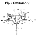
- Fig. 1 shows a conventional reservoir.
- a tank 101 made of metal or synthetic resin has an outflow passage and an inflow passage (not shown) at the bottom thereof and an inlet 102 at the top thereof.
- a cap made of synthetic resin has a ventilating structure and is detachably attached to the tank 101 to cover the inlet 102.
- the cap consist of an outer portion 103, an inner portion 104 which is arranged, relative to the outer portion, to provide a labyrinth 105 (vent gap) therebetween, and a protruding portion 108 which is formed to protrude from a center portion of the inner portion 104 in a direction toward the inside of the tank 101.
- a vent hole 109 connected to the labyrinth 105 and a small hole 110 communicating the vent hole 109 with the inside of tank 101 is formed in the protruding portion 108.
- a level-gauge 111 is integrally formed with the lower portion of the protruding portion 108.
- the cap is attached to the tank 101 by engagement hooks 112 which are mounted on the protruding portion 108, and which are biased upwardly by a lock-spring 113 to engage a stopper 114 which is formed at an edge of the inlet 102.
- the aforementioned reservoir has a problem in that the operation fluid leaks from the tank 101 through the small hole 110, the vent hole 109 and the labyrinth 105 when the tank 101 is shaken while driving on rough roads and the operation fluid is splashed. It is especially remarkable when the volume of the operation fluid is increased by high temperature and its level has risen.
- the present invention provides a reservoir that comprises a tank having an inlet, and a cap for covering the inlet.
- the cap further comprises an outer portion, an inner portion, a labyrinth, a protruding portion, a vent hole and a check valve.
- the inner portion is arranged in the outer portion to define the labyrinth therebetween.
- the labyrinth is opened to the exterior of the tank.
- the protruding portion is formed on the center of the inner portion to protrude a direction of the inside of the tank, wherein the vent hole is formed to communicate between inside of the tank and the labyrinth.
- the check valve is arranged on an upper end of the vent hole, and constructed to permit the communication of air through the vent hole and to prevent a leak of the fluid through the vent hole.
- the check valve is made of an elastic material and comprises a valve-sheet, a boss, a flange, a through hole and a valve portion.
- the valve-sheet has a center hole and is attached on the inner portion.
- the boss is inserted in the center hole of the valve-sheet.
- the flange is formed at an upper end of the boss and blocks a clearance between the boss and the center hole of the valve-sheet.
- the through hole is formed in the boss.
- the valve portion is formed at a lower end of the boss to elastically close a lower end of the though hole.
- the flange is elastically deformed to permit the air in the tank to flow out when the pressure in the tank is higher than the pressure outside of the tank
- the valve portion is elastically deformed to permit the air outside of the tank to flow in when the pressure in the tank is lower than the pressure outside of the tank.
- leakage of the operation fluid is prevented by the flange and the valve portion.
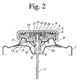
- FIG. 2 and Fig. 3 show a reservoir according to the first embodiment of the present invention.
- a tank 1 that reserves operation fluid is made of metal or synthetic resin.
- An outflow passage and an inflow passage (not shown) which are connected to a hydraulic apparatus such as a power steering apparatus are formed at the bottom of the tank 1.
- an inlet 2 for filling operation fluid is formed at the top of the tank 1, and a cap having a ventilating structure is detachably attached thereon.
- the cap that has a ventilating structure comprises an outer portion 3, an inner portion 4, a protruding portion 8 and a check valve 20.
- the inner portion 4 is formed to define a chamber 7 at the inside center thereof.
- the outer portion 3 and the inner portion 4 are arranged to provide a labyrinth 5 (vent gap) therebetween.
- a clearance 6 is provided between an inner surface of the outer portion 3 and a peripheral surface of the inner portion 4.
- the protruding portion 8 is formed at the center of the inner portion 4 to protrude in the direction of the inside of the tank 1.
- a vent hole 9 that is communicated with the labyrinth 5 is formed in the protruding portion 8.
- a small hole 10 that communicates the vent hole 9 with the inside of the tank 1 is horizontally opened at side portion of the protruding portion 8.
- a level-gauge 11 for gauging a level of the operation fluid is integrally formed with the lower portion of the protruding portion 8.
- the clearance 6 and the chamber 7 function as a breather B' that permits communication between the inside of the tank 1 and the outside (atmospheric air).
- Two hooks 12 having an 180 degree phase difference with each other are mounted to the protruding portion 8 so as to be able to slide vertically thereon, but to be unable to turn on the protruding portion 8.
- the hooks 12 are biased upwardly by a lock-spring 13 that is arranged between the hooks 12 and a shoulder of the protruding portion 8.
- a stopper 14 is formed at an edge of the inlet 2.
- Two notches (not shown) which have a 180 degree phase difference are formed at the stopper, so that the hooks 12 are able to engage the stopper 14.
- the check valve 20 will be described hereinafter.
- the check valve 20 is disposed in the chamber 7 to permit ventilation between the inside and the outside of the tank 1, and to prevent leaks of the operation fluid to the outside of the tank 1.
- the check valve 20 which is made of an elastic material such as rubber or soft-synthetic resin is disposed on the inner portion 4 to close the upper end of the vent hole 9.
- the check valve 20 consists of a flange 21, a boss 22, a through hole 23, a valve portion 24 and a valve-sheet 25.
- the valve-sheet 25 is fixed on the inner portion 4 by being glued at the periphery of the bottom surface thereof.
- the boss 22 is inserted into a center hole 26 formed on the valve-sheet 25 so that the flange 21 closes a clearance between the boss 22 and the center hole 26.
- the flange 21 prevents communication between the vent hole 9 and the chamber 7
- the pressure in the tank 1 is higher than the pressure outside of the tank 1 (atmospheric pressure)
- the flange 21 is elastically deformed upwardly and permits air in the tank 1 to flow out.
- the valve portion 24 is formed so that the lower end of the through hole 23 is closed by its elasticity. Therefore, the valve portion 24 prevents communication between the vent hole 9 and the through hole 23.
- the lower end of the valve portion 24 is elastically deformed and permits the air outside of the tank 1 to flow into the tank 1.
- the check valve 20 Since the check valve 20 has the aforementioned structure, the air outside of the tank 1 can flow into the tank 1 through the labyrinth 5, the chamber 7, the check valve 20, the vent hole 9 and the small hole 10 because the valve portion 24 is deformed by the pressure of the air, and the air in the tank 1 can flow out through the small hole 10, the vent hole 9, the center hole 26, the chamber 7 and the labyrinth 5 because the flange 21 is deformed by the pressure of the air.
- the operation fluid splashed by vibration flows into the vent hole 9 through the small hole 10 because of the existence of the check valve 20, i.e., the lower portion of the check valve 20 is closed by the valve portion 24, and the center hole 26 of the valve-sheet 25 is closed by the flange 21.
- the flange 21 will not be deformed by the splashed fluid.
- the check valve 20 is assembled to the cap so that the valve-sheet 25, in which the boss 22 of the check valve 20 is inserted in the center hole 26 thereof, is fixed on the inner portion 4. According to such an assembling method, inconsistency caused during the assembly of the check valves 20 is significantly reduced. Therefore, the quality of the check valves 20, i.e., valve opening pressure at the flanges 21, becomes consistent.
- an inner portion 4' of the second embodiments is the same as the form of the inner portion 104 of the aforementioned related art, but with a check valve 20' installed therein.
- the construction of the check valve 20' is the same as that of the check valve 20 of the first embodiment.
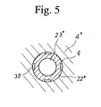
- the check valve 20' is made of an elastic material such as rubber or soft-synthetic resin and consists of a flange 21', a boss 22', a through hole 23'and a valve portion 24', and in this embodiment further comprises a plurality grooves 30.
- the boss 22' is inserted into the vent hole 9 so that the flange 21' closes the upper end of the vent hole 9.
- the plurality grooves 30 are formed on a peripheral surface of the boss 22' that contacts an inner surface of the vent hole 9 in order to communicate the vent hole 9 with the chamber 7.
- the flange 21' prevents communication between the vent hole 9 and the labyrinth 5
- the flange 21' is elastically deformed and permits air in the tank 1 to flow out.
- the valve portion 24' is formed so that the lower end of the through hole 23' is closed by its elasticity to prevent communication between the vent hole 9 and the labyrinth 5.
- the valve portion 24' is elastically deformed and permits the air outside of the tank 1 to flow into the tank 1.
- the reservoir of the second embodiment also achieves the effect that the air outside of the tank 1 can flow into the tank 1 through the labyrinth 5, the chamber 7, the check valve 20', the vent hole 9 and the small hole 10 so that the valve portion 24' is deformed by pressure of the air, and the air in the tank 1 can flow out through the small hole 10, the vent hole 9, the grooves 30, the chamber 7 and the labyrinth 5 so that the flange 21' is deformed by pressure of the air.
- the operation fluid splashed by vibrations flows into the vent hole 9 through the small hole 10 because of the existence of the check valve 20, i.e., the lower portion of the check valve 20' is closed by the valve portion 24', and the upper end of the vent hole 9 is closed by the flange 21'.
- the flange 21' will not be deformed by the splashed fluid.
- the reservoir of the present invention can be achieved by installing the check valve 20' in a conventional reservoir.
- the reservoir of the present invention is described as provided for a power steering apparatus, the present invention is not so limited and can be adapted to other reservoirs such as a reservoir for clutch oil of a clutch apparatus or for brake oil of a brake apparatus.
- the reservoir includes a tank having an inlet, and a cap for covering the inlet.
- the cap further comprises an outer portion, an inner portion, a labyrinth, a protruding portion, a vent hole and a check valve.
- the inner portion is arranged in the outer portion to define the labyrinth therebetween.
- the labyrinth is opened to outside of the tank.
- the protruding portion is formed on the center of the inner portion to protrude in a direction of the inside of the tank, in which the vent hole is formed to communicate between inside of the tank and the labyrinth.
- the check valve is arranged on an upper end of the vent hole, and is constructed to permit the communication of air through the vent hole and to prevent a leak of the fluid through the vent hole.
Landscapes
- Engineering & Computer Science (AREA)
- Mechanical Engineering (AREA)
- General Engineering & Computer Science (AREA)
- Transportation (AREA)
- Physics & Mathematics (AREA)
- Combustion & Propulsion (AREA)
- Chemical & Material Sciences (AREA)
- Fluid Mechanics (AREA)
- Closures For Containers (AREA)
- Supply Devices, Intensifiers, Converters, And Telemotors (AREA)
- Transmission Of Braking Force In Braking Systems (AREA)
- Power Steering Mechanism (AREA)
- Check Valves (AREA)
Applications Claiming Priority (2)
| Application Number | Priority Date | Filing Date | Title |
|---|---|---|---|
| JP2001279037A JP2003081080A (ja) | 2001-09-14 | 2001-09-14 | リザーバ |
| JP2001279037 | 2001-09-14 |
Publications (2)
| Publication Number | Publication Date |
|---|---|
| EP1314896A2 true EP1314896A2 (de) | 2003-05-28 |
| EP1314896A3 EP1314896A3 (de) | 2005-12-28 |
Family
ID=19103299
Family Applications (1)
| Application Number | Title | Priority Date | Filing Date |
|---|---|---|---|
| EP02020392A Withdrawn EP1314896A3 (de) | 2001-09-14 | 2002-09-12 | Behälter mit Belüftungseinrichtung |
Country Status (3)
| Country | Link |
|---|---|
| US (1) | US20030062371A1 (de) |
| EP (1) | EP1314896A3 (de) |
| JP (1) | JP2003081080A (de) |
Cited By (4)
| Publication number | Priority date | Publication date | Assignee | Title |
|---|---|---|---|---|
| DE102011104394A1 (de) * | 2011-06-16 | 2013-01-03 | Volkswagen Aktiengesellschaft | Flüssigkeitsbehälter für eine Hydraulikanlage und Anordnung eines solchen Flüssigkeitsbehälters in einem Fahrzeug |
| DE102014200261A1 (de) * | 2014-01-10 | 2015-07-16 | Zf Friedrichshafen Ag | Ölbehälter |
| RU2563415C1 (ru) * | 2013-04-24 | 2015-09-20 | Др. Инж. х.к. Ф. Порше Акциенгезелльшафт | Крышка масляного бака |
| CN109383922A (zh) * | 2017-08-14 | 2019-02-26 | 罗伯特·博世有限公司 | 盖组件和包括盖盖组件的储液器 |
Families Citing this family (12)
| Publication number | Priority date | Publication date | Assignee | Title |
|---|---|---|---|---|
| JP4506457B2 (ja) * | 2004-12-27 | 2010-07-21 | 株式会社ジェイテクト | 樹脂製リザーバ |
| KR100754131B1 (ko) * | 2005-08-01 | 2007-08-30 | 삼성에스디아이 주식회사 | 데이터 구동회로와 이를 이용한 유기 발광 표시장치 및그의 구동방법 |
| FR2903971B1 (fr) * | 2006-07-20 | 2011-09-02 | Jtekt Hpi | Bouchon pour une ouverture d'un reservoir et reservoir comprenant un tel bouchon |
| ATE531592T1 (de) | 2008-05-21 | 2011-11-15 | Parker Hannifin Corp | Entlüfter mit hydraulischem flüssigkeitssystem mit unabhängigen einlass-/auslassströmungswegen |
| DE102010010412B3 (de) * | 2010-03-05 | 2011-06-16 | Bayerische Motoren Werke Aktiengesellschaft | Bremsflüssigkeitsreservoir, insbesondere für Motorräder |
| US10542731B2 (en) * | 2012-06-27 | 2020-01-28 | Ctb, Inc. | Breather cap assembly |
| US8904962B2 (en) * | 2012-06-27 | 2014-12-09 | Ctb, Inc. | Breather cap assembly |
| DE102013005375A1 (de) * | 2013-01-07 | 2014-07-10 | Continental Teves Ag & Co. Ohg | Druckmittelbehälter für eine hydraulische Kraftfahrzeugbremsanlage |
| JP6943013B2 (ja) * | 2017-05-16 | 2021-09-29 | 住友ゴム工業株式会社 | パンク修理用のボトルユニット |
| US10668908B2 (en) * | 2017-11-14 | 2020-06-02 | Robert Bosch Gmbh | Brake fluid reservoir |
| US10744992B2 (en) | 2018-05-15 | 2020-08-18 | Robert Bosch Gmbh | Sealing device for a dynamic reservoir |
| CN114233885B (zh) * | 2021-11-19 | 2024-03-19 | 中车长江车辆有限公司 | 一种通气阀和保温集装箱 |
Family Cites Families (14)
| Publication number | Priority date | Publication date | Assignee | Title |
|---|---|---|---|---|
| US2622762A (en) * | 1947-05-14 | 1952-12-23 | Malcolm W Fraser | Valved closure assembly |
| US3155110A (en) * | 1962-12-03 | 1964-11-03 | Vernay Laboratories | Rubber check and relief valve |
| US3861557A (en) * | 1973-08-06 | 1975-01-21 | Dexter Automatic Products Co I | Vent cap |
| US4165816A (en) * | 1978-04-10 | 1979-08-28 | Dapco Industries | Vent cap |
| GB2043803B (en) * | 1979-03-09 | 1983-08-03 | Skf Uk Ltd | Seals |
| US4337875A (en) * | 1981-03-12 | 1982-07-06 | Atwood Vacuum Machine Company | Overflow and vent cap for a container |
| DE3206520A1 (de) * | 1982-02-24 | 1983-09-01 | Alfred Teves Gmbh, 6000 Frankfurt | Ventilanordnung fuer ausgleichsbehaelter hydraulischer bremsanlagen |
| JPH0720043Y2 (ja) * | 1989-12-20 | 1995-05-10 | 自動車機器株式会社 | リザーバキャップ |
| DE4300441C1 (de) * | 1993-01-09 | 1993-12-02 | Inst Maschinenelemente Uni Stu | Vorrichtung zum Ent- und Belüften von Maschinengehäusen |
| DE4315701C2 (de) * | 1993-05-11 | 1995-03-23 | Schuetz Werke Gmbh Co Kg | Sicherheitsventil aus Kunststoff für Behälter |
| DE4427738B4 (de) * | 1994-08-05 | 2005-11-24 | Fa. Andreas Stihl | Arbeitsgerät mit einem Verbrennungsmotor |
| US5752746A (en) * | 1995-12-15 | 1998-05-19 | Stemco Inc | Hubcap with vented closure |
| US5711901A (en) * | 1996-06-05 | 1998-01-27 | Walbro Corporation | Carburetor having temperature-compensated purge/primer |
| US5860708A (en) * | 1997-07-11 | 1999-01-19 | Stemco Inc | Contaminant excluding hubcap vent plug |
-
2001
- 2001-09-14 JP JP2001279037A patent/JP2003081080A/ja active Pending
-
2002
- 2002-09-12 EP EP02020392A patent/EP1314896A3/de not_active Withdrawn
- 2002-09-16 US US10/244,015 patent/US20030062371A1/en not_active Abandoned
Cited By (5)
| Publication number | Priority date | Publication date | Assignee | Title |
|---|---|---|---|---|
| DE102011104394A1 (de) * | 2011-06-16 | 2013-01-03 | Volkswagen Aktiengesellschaft | Flüssigkeitsbehälter für eine Hydraulikanlage und Anordnung eines solchen Flüssigkeitsbehälters in einem Fahrzeug |
| RU2563415C1 (ru) * | 2013-04-24 | 2015-09-20 | Др. Инж. х.к. Ф. Порше Акциенгезелльшафт | Крышка масляного бака |
| DE102014200261A1 (de) * | 2014-01-10 | 2015-07-16 | Zf Friedrichshafen Ag | Ölbehälter |
| CN109383922A (zh) * | 2017-08-14 | 2019-02-26 | 罗伯特·博世有限公司 | 盖组件和包括盖盖组件的储液器 |
| CN109383922B (zh) * | 2017-08-14 | 2022-01-11 | 罗伯特·博世有限公司 | 盖组件和包括盖盖组件的储液器 |
Also Published As
| Publication number | Publication date |
|---|---|
| JP2003081080A (ja) | 2003-03-19 |
| EP1314896A3 (de) | 2005-12-28 |
| US20030062371A1 (en) | 2003-04-03 |
Similar Documents
| Publication | Publication Date | Title |
|---|---|---|
| US20030062371A1 (en) | Reservoir having a ventilating structure | |
| US5558244A (en) | Oil reservoir having a cap with cylindrical baffles defining labyrinth passage | |
| US7854345B2 (en) | Vehicular fuel tank arrangement | |
| EP1212560B1 (de) | Ventil und verfahren zur befestigung in einem behälter | |
| US5868119A (en) | Fuel tank venting system for vehicles | |
| US5782262A (en) | Gas ventilation apparatus for a fuel tank | |
| EP2518302B1 (de) | Ventilvorrichtung für einen brennstofftank | |
| US20040244371A1 (en) | Brake hydraulic control actuator for vehicles | |
| MXPA03002743A (es) | Bomba de combustible, transmisor de nivel y valvula de volcadura/ventilacion para un tanque de combustible. | |
| RU2593328C2 (ru) | Топливный клапан | |
| US20060185741A1 (en) | Cover on power steering reservoir assembly | |
| CN108691991B (zh) | 通气装置 | |
| CN118404976A (zh) | 燃料箱用阀装置 | |
| JP3780828B2 (ja) | 作動油タンク | |
| US7299820B2 (en) | Hydraulic fluid reservoir | |
| JPH04330311A (ja) | 潤滑オイルのための遅延部材 | |
| US20050269321A1 (en) | Housing for an electronic or mechatronic unit | |
| US6782917B2 (en) | Reciprocating cone anti-drainback apparatus | |
| US6382230B1 (en) | Ball valve | |
| US7273087B2 (en) | Assembly | |
| JP2782221B2 (ja) | 動力舵取装置用リザーバタンク | |
| JPH09263232A (ja) | オイルリザーバ | |
| CN107120415B (zh) | 通气装置 | |
| CN107614937A (zh) | 铁路车辆用齿轮装置 | |
| JP4543448B2 (ja) | リザーバ用キャップ |
Legal Events
| Date | Code | Title | Description |
|---|---|---|---|
| PUAI | Public reference made under article 153(3) epc to a published international application that has entered the european phase |
Free format text: ORIGINAL CODE: 0009012 |
|
| AK | Designated contracting states |
Designated state(s): AT BE BG CH CY CZ DE DK EE ES FI FR GB GR IE IT LI LU MC NL PT SE SK TR |
|
| AX | Request for extension of the european patent |
Extension state: AL LT LV MK RO SI |
|
| PUAL | Search report despatched |
Free format text: ORIGINAL CODE: 0009013 |
|
| AK | Designated contracting states |
Kind code of ref document: A3 Designated state(s): AT BE BG CH CY CZ DE DK EE ES FI FR GB GR IE IT LI LU MC NL PT SE SK TR |
|
| AX | Request for extension of the european patent |
Extension state: AL LT LV MK RO SI |
|
| AKX | Designation fees paid |
Designated state(s): DE FR GB |
|
| RAP1 | Party data changed (applicant data changed or rights of an application transferred) |
Owner name: JTEKT CORPORATION |
|
| RIN1 | Information on inventor provided before grant (corrected) |
Inventor name: HIRAO, NAOYUKI |
|
| STAA | Information on the status of an ep patent application or granted ep patent |
Free format text: STATUS: THE APPLICATION IS DEEMED TO BE WITHDRAWN |
|
| 18D | Application deemed to be withdrawn |
Effective date: 20060530 |